
Brendan Guitron – Project Manager
Daniel Enverga – Mission, Systems, and Test
Henry Martinez – Design and Manufacturing
Wilder Pineda – Electronics and Controls
by Brendan Guitron
The Spring 2019 Pathfinder Solar Array Generation 3 uses a distributed network of solar modules as a means of providing power to the Pathfinder’s rechargeable battery. The updated design allows the operator to retrieve operational current, voltage, and temperature values of individual solar modules for aid in troubleshooting. In this iteration, further precautions have been taken to improve the maintainability of the electronic system.
by Brendan Guitron
The Pathfinder Solar Array shall designed to be self-sufficient by utilizing a distributed network of solar panels to recharge the Pathfinder’s battery. The physical design of the project will resemble the ones found on NASA’s Mars exploration Rovers, Spirit and Opportunity. The Pathfinder Solar Array shall be able to provide telemetry to the Arxterra control Panel.
The Pathfinder Solar Array Generation 3 project aims to improve upon all aspects of the physical and electronic designs produced in the second generation. An updated electronic design for the solar modules will simplify the connections made between the active and passive components contained within each module. It will also reduce the number of connectors required by each module. In addition to current and voltage telemetry, the modules will now measure and report temperature values. A new design for an enclosure with serve to both secure the solar modules and associated cabling in place and increase protection to the PCBs and embedded components. An aluminum trimming will be incorporated to hold the form factor of the panels in a stationary position. Completion of the Solar Panel Array Generation 3 will be achieved by May 13th, 2019.
by Brendan Guitron
The mission for the 3rd Generation Pathfinder Solar Array will commence at the front of the CSULB library, which is the starting location of the obstacle course defined by the Pathfinder Generation 5 Team. At the beginning of the course, the Pathfinder Solar Array system will charge the Pathfinder’s battery from a 50% charge to a 60% charge over a period of 1.2 hours (72 minutes). While the vehicle is in transit through the course, the Pathfinder Solar Array will continue to provide power to the Pathfinder’s battery. Telemetry readings of the current, voltage, and temperature measurements will be demonstrated in the Central Quad on California State University, Long Beach located at 33°46’40.7″N 118°06’48.9″W, which is the end of the course defined by the Pathfinder Generation 5 team.
by Brendan Guitron
The modular design of the solar array network allows for replacement of as little as 1 solar cell at a time, whether it be an active or passive cell. Individual solar modules can provide an operating voltage, current, and temperature measurements for aid in troubleshooting. A new enclosure design incorporated underneath the panel adds an extra layer of protection to the PCBs and allows for easier assembly and disassembly compared to the previous design. Updated PCB designs are now utilize only one connector on the passive cell and two connectors on the active cells.
by Brendan Guitron
The Pathfinder Solar Array Generation 3 will remain in compliance with constraints on the project imposed by The Robot Company (i.e., CSULB) and Project Stakeholders. This includes University and applicable environmental, health, and safety standards and those safety standards specifically associated with the product (e.g., Children’s Toys).
NFPA 70E Standard for Electrical Safety Requirements for Employee Workplaces
CSULB Environmental Health & Safety (EH&S)
IEEE National Electrical Safety Code (NESC)
ASTM F963-17, The Standard Consumer Safety Specification for Toy Safety
CSULB Physical Planning & Facilities Management (PPFM) Environmental Compliance Electronic Waste Handling and Disposal Procedures. These procedures shall be followed for the disposal of all batteries.
by Brendan Guitron
Subcategories: Cost, Extensibility, Interoperability, Maintainability, Quality, Marketability, and Schedule
The Pathfinder Solar Array Project shall be constrained to a Cost not to exceed $665.21.
All project Schedules shall be constrained to a completion date of Monday May 13, 2019. Project completion includes documentation and materials purchased by or loaned to the project.
Extensibility is designed into the Pathfinder solar array by way of replaceable modules by rectangular 10-pin ribbon connectors connector located on active and passive cell PCBs. With each solar cell capable of disassembly to the cell level, individual parts parts can be easily replaced. All active or passive cells shall contain at least one one custom PCB. Surface Mount Technology (SMT) will be employed unless a waiver for through-hole parts is granted.
Maintainability: Disassemble and Reassemble of the Pathfinder Solar Array shall be constrained to less than 20 minutes (10 + 10 minutes). Disassembly: The panels supporting the solar array system is clear of all electronic components and connectors. All mechanical assemblies are removed from the Pathfinder vehicle.All electronic assemblies and associated connectors and sensors are disconnected. A functional test of the robot is conducted after reassembly to confirm its functionality. All project may reference a cable tree as well as an assembly diagram as necessary. This requirement is demonstrated/verified on the last day of the schedule. Projects may request a waiver with justification.
Subcategories: Accessibility, Aesthetics, and Usability
To enhance Aesthetics, the robot shall be designed in such a way that there are no dangling or exposed wires. Compliance with this requirement, includes the use of keyed and clearly labeled connectors between all electronic and electromechanical components. Do not use jumper wires; ribbon cables are preferred but not required. Loose wires should be contained using spaghetti tubing (not shrink tubing).
To enhance Aesthetics, the form factor of the Pathfinder Solar array shall be constrained by JPL’s Opportunity or Spirit Rovers.
Usability of the Pathfinder Solar Array shall be enhanced by adding autonomous functions and/or by use of the Arxterra phone and control panel application as dictated by the assigned mission.
Subcategories: Constructability, Size, Weight, and Power (SWAP)
Constructability of the Pathfinder Solar Array shall be documented at the CDR and approved by the president of the TRC robot company. Constraints imposed by this requirement include the use of connectors with integrated cable fasteners, H-channel aluminium trimming, and silicon based adhesive for use in stationary parts. No gaps greater than 1 millimeter, and immediate access to all external connectors (GH connectors, dip-switches).
Manufacturability of Pathfinder Solar Array shall be demonstrated by compliance with the library’s Innovation Space and AoSA cutting services. Projects may request a waiver with justification. This requirement is waived for 3D prints provided by the library’s Innovation Space. In its place, all 3D prints provided by the library’s Innovation Space should minimize the number of files to be printed. Justification should be provided if more than one (1) file is required.
The Size of the electronics enclosure, shall be constrained to be no greater than the custom PCB sizes created for the passive and active cell PCBs and associated mounting hardware.
Power to the Pathfinder Solar Array shall be provided by the 12 Volt motorcycle battery associated with the Pathfinder Chassis The 12 Volt battery is 7A-Hr acid battery. All Safety regulations as defined in Section 4.3 Hazards and Failure Analysis of this document shall apply to the shipping, handling, storage, and disposal of LiPo batteries.
Back of the envelope calculations and experiments shall be conducted to set the diameter of Power carrying wires. Follow the American Wire Gauge (AWG) standard when defining the diameter of power carrying wires.
Subcategories: Environmental Standards, Sustainability, Toxic waste (Solar panels), Health and Safety, Ergonomics
All standards, codes, and regulations as defined in the “Engineering Standards and Constraints” Section of this document shall apply.
All Lithium (Li-ion, Li-polymer) batteries shall be purchased with and stored, when not in use, in a fire and explosion proof battery bag.
Software shall be written in the Arduino De facto Standard scripting language and/or using the GCC C++ programming language, which is implements the ISO C++ standard (ISO/IEC 14882:1998) published in 1998, and the 2011 and 2014 revisions. Required exceptions to this standard can be found here.
The Pathfinder Solar Array shall be in compliance with the 3DoT Command and Telemetry Packet specification.
All Arduino ATmega telemetry shall be controlled via Bluetooth 4.0 in compliance with the Bluetooth Special Interest Group (SIG) Standard (supersedes IEEE 802.15.1).
by Brendan Guitron & Daniel Enverga
L1.1 Form Factor: The Pathfinder solar array system shall follow the form factor of the solar array system found on JPL’s Opportunity & Spirit rovers.
L1.2 The Pathfinder solar array system shall be comprised of a series-parallel network of solar array modules, capable of delivering data from at least 2 module.
L1.3 The distributed network of solar cells should continuously charge the Pathfinder’s battery while the vehicle is both operating and not operating.
L1.4 Custom PCBs: The Pathfinder Solar Array shall incorporate custom PCB designs to collect solar module charging data and transmit power from the solar array to the power hub.
L1.5 The Pathfinder’s solar array telemetry shall provide real time charging data to the operator.
L1.6 The Pathfinder Solar Array project will employ plastic “hat” enclosures to provide protection to the PCB’s.
by Brendan Guitron & Daniel Enverga
L2.1.1: The solar array system will be comprised of 4 aluminum panels that will support a distributed network of solar modules.
L2.1.2: There will be 4 unique panel designs comprising of the Main Panel with dimensions 444.50mm x 403.8mm x 2.00mm, Tail Panel with dimensions 436.8mm x 209.55mm x 2.00mm, Left Wing, and Right Wing Panels sharing the same dimensions of 723.9mm x 209.55mm x 2.00mm
L2.1.3: The main panel shall use 6mm diameter screws to fasten onto a baseplate to withstand the shaking of a human to replicate the shaking during movement of rocky terrain.
L2.1.4: The main panel shall be capable of supporting the weight of the other panels with less than 4 degrees of displacement on the the other three panels in an open, stationary position by attaching aluminum H-Channel trimming to the edges of the main panel.
L2.2.1: One solar array module will contain 3 solar cells connected in series.
L2.2.2: The main panel and tail panel will each contain 3 solar modules connected in parallel.
L2.2.3: The left wing and right wing panels will each contain 5 solar module connected in parallel.
L2.2.4: The solar arrays from all the panels will be connected in parallel.
L2.3.1: Module Voltage (Performance): One solar module shall be capable of providing 15 or more volts to the terminals of the battery charger when placed under normal classroom lights with an unobstructed zenith of 90°.
L2.3.2: Module Current (Performance): One solar module shall be capable of providing 0.027 or more amps to the terminals of the battery charger when placed under normal classroom lights with an unobstructed zenith of 90°.
L2.3.3: Charging Speed (Performance): The solar array should be capable of recharging the battery from 50% to 60% of its total value in 1.25 hours under sunny conditions with no clouds.
L2.4.1: Power Delivery by Cell: The solar module will contain three custom PCBs.
L2.4.2: Data Collection: The custom PCB on the active cell in the solar module shall be capable of measuring the voltage through the module.
L2.4.3: Data Collection: The custom PCB on the active cell in the solar module shall be capable of measuring the current through the module.
L2.4.4: Data Collection: The custom PCB on the active cell in the solar module should be capable of measuring the temperature through the module.
L2.4.5: Power Combination by Module: The active cell PCB shall be capable of summing currents from at least 2 modules in parallel.
L2.4.6: Power Combination by Panel: The Power Hub PCB shall be capable of summing at least 2 solar array currents in parallel.
L2.4.7: Cable/Connection Type: The active and passive cell PCB designs will employ 10-pin, ribbon cables and ribbon cable connectors as the preferred method of transmitting power.
L2.5.1: Module Charging Data: The Arxterra Control Panel shall display operational voltage and current values of 6 modules situated on the Pathfinder’s solar panels.
L2.5.2: Total Charging Data: The Arxterra Control Panel shall display the total operational voltage and current of the distributed network being delivered to the terminals of the battery charger.
L2.5.3: Communication Protocol: The Arduino MEGA situated within the chassis will employ “I2C” communication protocol to relay telemetric values from the Pathfinder’s Solar Panels.
L2.6.1: Electrical Protection: All PCBs will be housed in an enclosure on the underside of the solar array panels and protected from direct contact of debris ejected from rocky terrain
L2.6.2: Cable Management: Loose cabling will be managed with built-in “seatbelts” in the PCB enclosures.
L2.6.3: Heat Resistance: The PCB “hat” enclosures will be manufactured out of high-heat resistant material.
by Daniel Enverga
The mass report allocation is 22.68 kg. This was determined in a stress test conducted by the Pathfinder Chassis Generation 3 team. As a result, we know that the Pathfinder chassis is capable of supporting up to 22.68 kg (50 lbs) of weight atop of the base of the Chassis body.
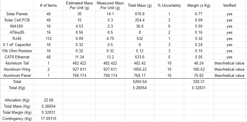
Figure 1. Mass Shared Resource Report
by Daniel Enverga
The Power Report features two different allocations because we are providing power both going in and power going out. The CMP12 Solar Charge Controller can only have a max current of 10A which falls under the Allocation Out. The provided Lead-Acid battery has a max current of 7A which will be the Allocation In.
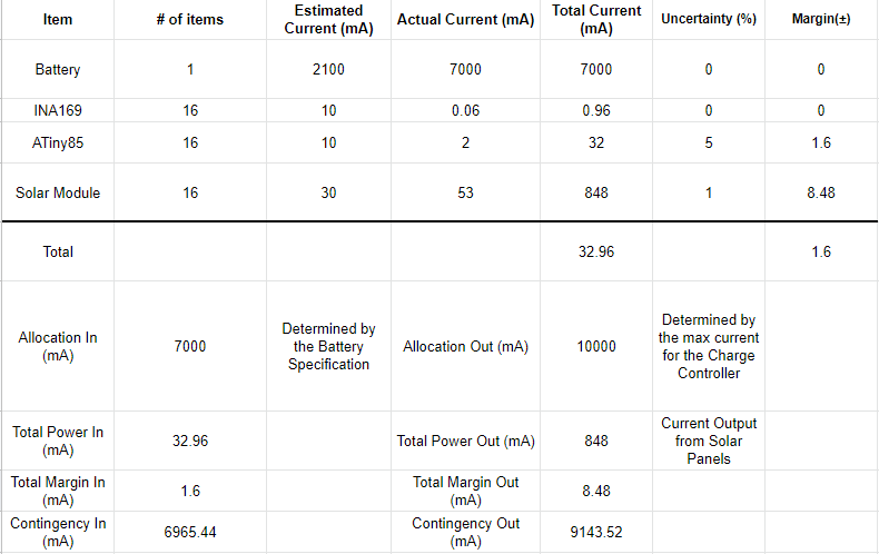
Figure 2. Power Shared Resource Report
by Brendan Guitron
by Brendan Guitron
The Work Breakdown Structure (WBS) and Product Breakdown Structure (PBS) provide a determination on how responsibility of specific tasks are delegated to the members of the Pathfinder Solar Array team.
The Work Breakdown Structure breaks down all of the work that must completed by each group member for the entire project. The project manager is in charge of planning and executing the Pathfinder Solar Array project. A mission, systems, and test engineer, electronics and controls engineer, and design and manufacturing engineer have been selected to support the project by producing designs and documentation in an effort to improve the overall design of the product. Under each engineer are the general duties that the engineer is responsible for. Each of these duties are outlined by specific tasks listed next to it.
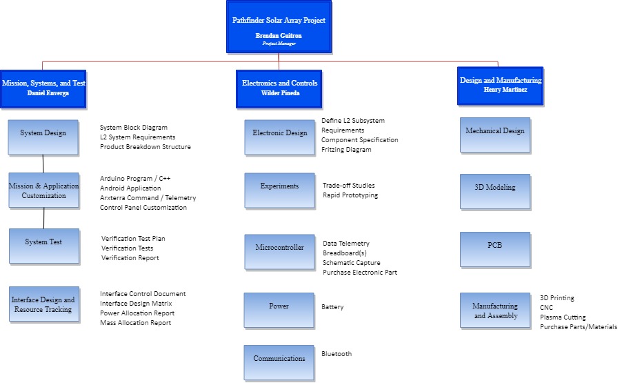
Figure 3. Work Breakdown Structure
The Product Breakdown structure outlines the components of the Pathfinder Solar array into its hardware and software components. Dividing the project into these categories allows each group member to clearly see what parts of the product they will be responsible for delivering at the completion date. Under the category of Hardware, there are 2 subsets: Charging System and Panel Design. The charging system is comprised of all electronic designs that deal with the Solar Array. The panel design encompasses all physical and mechanical designs that will house and support the electronic system. The software category details the different codes that must be written for the solar array system .This includes writing a code for the onboard microprocessors that allow the solar array system to take measurements as well as another code to relay all telemetry from the onboard microprocessors to the main control hub situated within the Pathfinder chassis.
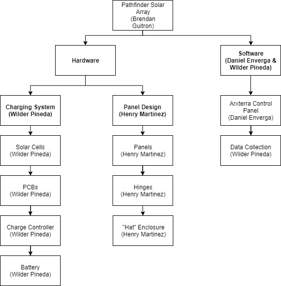
Figure 4. Product Breakdown Structure
by Brendan Guitron
The allocated budget for the Pathfinder Solar Array project was $665.21. However, it was determined that to completely populate all 16 modules with the PCBs and electronic components, as well as to manufacture all mechanical designs, the project would surpass the allocated budget at a total of $713.73. To ensure that we do not surpass the budget, we will not be populating the entire solar array.
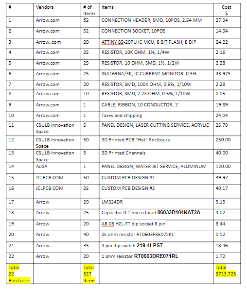
Figure 5. Budget Breakdown for fully populated solar array
by Brendan Guitron
A link to the Spring 2019 Pathfinder Solar array project schedule and burn down can be found below:
Spring 2019 Pathfinder Solar Array Project Schedule/Burn Down
Initially, I created a project schedule using the Google sheets app. This master list of assignments included information about each task such as who and which division is responsible for the task, the estimated duration, the actual duration, due date, status indication (incomplete, planned, or complete), and a column to place links directing the reader to the work done for that task. The schedule is simple and functional. Using simple calculations within the spreadsheet, you can calculate the project’s percentage complete based on the duration of hours spent on completed tasks compared to the total number of hours. Constructing a burn down report is also possible by plotting the duration of hours spent versus an ideal timeline on a daily basis.
by Henry Martinez
The Solar Array Generation 3 utilized the work of generation 2 as a preliminary design to determine an idea of what features needed to be focused on to meet the customers expectations.
By Henry Martinez
To get a good idea on how to complete the program objective, research on the previous generations was conducted. Playing around the arxterra website, specifically the final blog post in project section, allowed for the opportunity to view what the previous generations began and ended with, and final comments for the next generations to come. After the initial research, meetings with the customer gave further insight on what generation 3 should focus on. The mechanical design revolved around panels held in a stationary position attached by channels and an enclosure for the custom pcb’s. The electronic focused on producing working pcbs the allowed the user to view the current, voltage, and temperature of the solar array at a modular level.
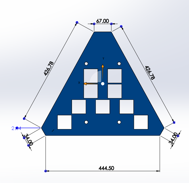
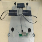
Figure 6. Main (Center) Solar Panel
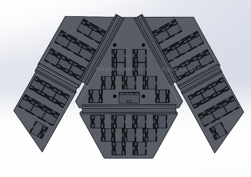
Figure 7. Underside of Solar Array/Arrangement of PCB “hat” style enclosures
by Henry Martinez
The Solar Array design was forced to start from scratch because the previous generation did not have any mechanical design or manufacturing completed. A big focus was placed on determining a method for securing the solar cells to the panels. After speaking with the customer it was decided the cabling system will be used to mount the solar cells onto the panels. Apart of the design is to attach the individual PCBs to the solar cells and place them into square cuts on the panels. A “Hat” style enclosure is then placed over the PCB to protect it from the outside environment as well as serve as a method for the cabling to secure the PCB and solar cell in place. The enclosure has small extrusions that allow for ribbon cable to slide through and hold in place. The cables act as a “seat belt” for the solar cells since the cable, secured by the enclosure, is connected to the PCB.
by Daniel Enverga
by Daniel Enverga
The System Block Diagram shows what will be contained within the 4 main panels of the Solar Array. Each panel will contain a set number of modules as shown in the block diagram. Also included in the System Block Diagram is what is contained within each module.
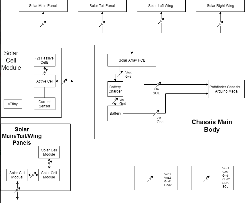
Figure 8. System Block Diagram
by Daniel Enverga
The Interface Matrix displays where everything will connect with each other. For the Pathfinder Solar Array, we will be connecting with an Arduino Mega using I2C communication and power which will feed into the Solar Array Interface/Power Hub PCB. From this PCB we connect to the 4 main panels in which will branch out again to each individual module included within the panels.
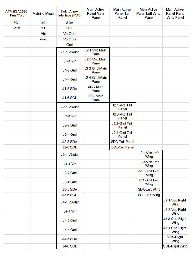
Figure 9. Interface Matrix
The next Interface Design Matrix is the matrix for the main panel solar array. This same matrix can be essentially repeated for each of the other three solar arrays; tail panel, right wing, left wing.
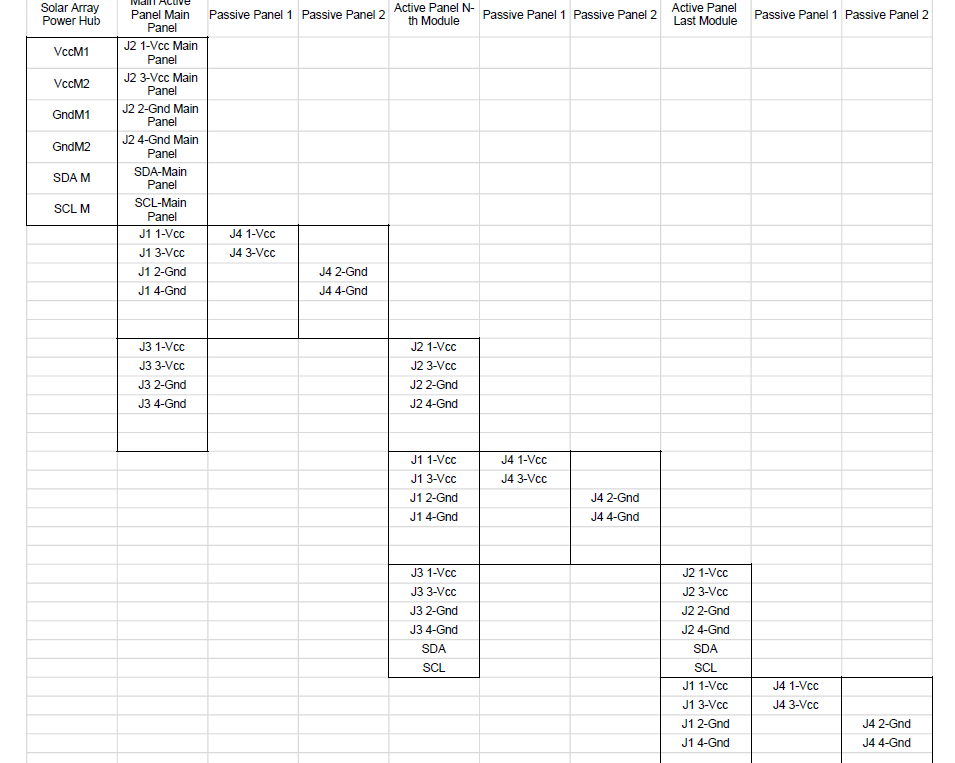
Figure 10. Interface Matrix Continued
The Pathfinder Solar Array Generation 3 will be interfaced with Pathfinder Chassis Generation 7. The Chassis and Solar Array systems will be interfaced mechanically by the connection of the base plate of the Solar Array system to the top of the Chassis body. The base plate will also function as the top enclosement of the Chassis body. The Chassis will also be able to accomodate the weight of the Solar Array system as the Solar Array will be placed on top of the Chassis. Electronically, the Chassis system will contain the Arduino Mega microcontroller which will allow I2C connections to allow the Solar Array system to transfer its telemetry to the Arxterra Control Panel. The Solar Array system is in charge of charging the lead-acid battery which is powering the entirety of the Chassis system. The use of the CMP12 Solar Charge Controller is necessary to regulate the charge from the Solar Panels to the Battery.
The Interface Control Document can be viewed here
by Daniel Enverga
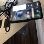
The following is the Arxterra Control Panel. Since the data from Pathfinder Solar Array will be interfaced with Pathfinder Chassis, the Chassis telemetry values will be viewed at the same time as the telemetry values of Solar Array. These extra values could be viewed by dragging the bar underneath the telemetry section of the control panel to view the other telemetry states. One of the biggest issues is that there is too many telemetry states required for the system. Each module has 3 different telemetry states with 16 modules for a total of 48 telemetry states/custom commands. However the Arxterra Control Panel can only handle 30 different different telemetry states/custom commands. Due to lack of testing, the select command is unable to be utilized in which the amount of telemetry states/commands is reduced from 48 to 16 different commands.
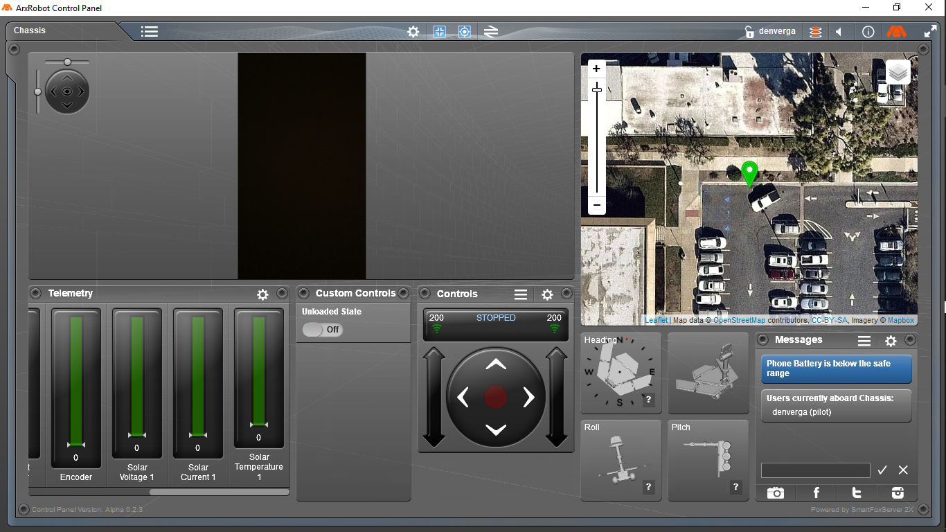
Figure 11. Arxterra Control Panel
Figure 12 shows that if the control panel when the select command is utilized to reduce the amount of telemetry values. This select command would determine whether the user wants to observe voltage, current, or temperature with the telemetry gauge module would show the value.
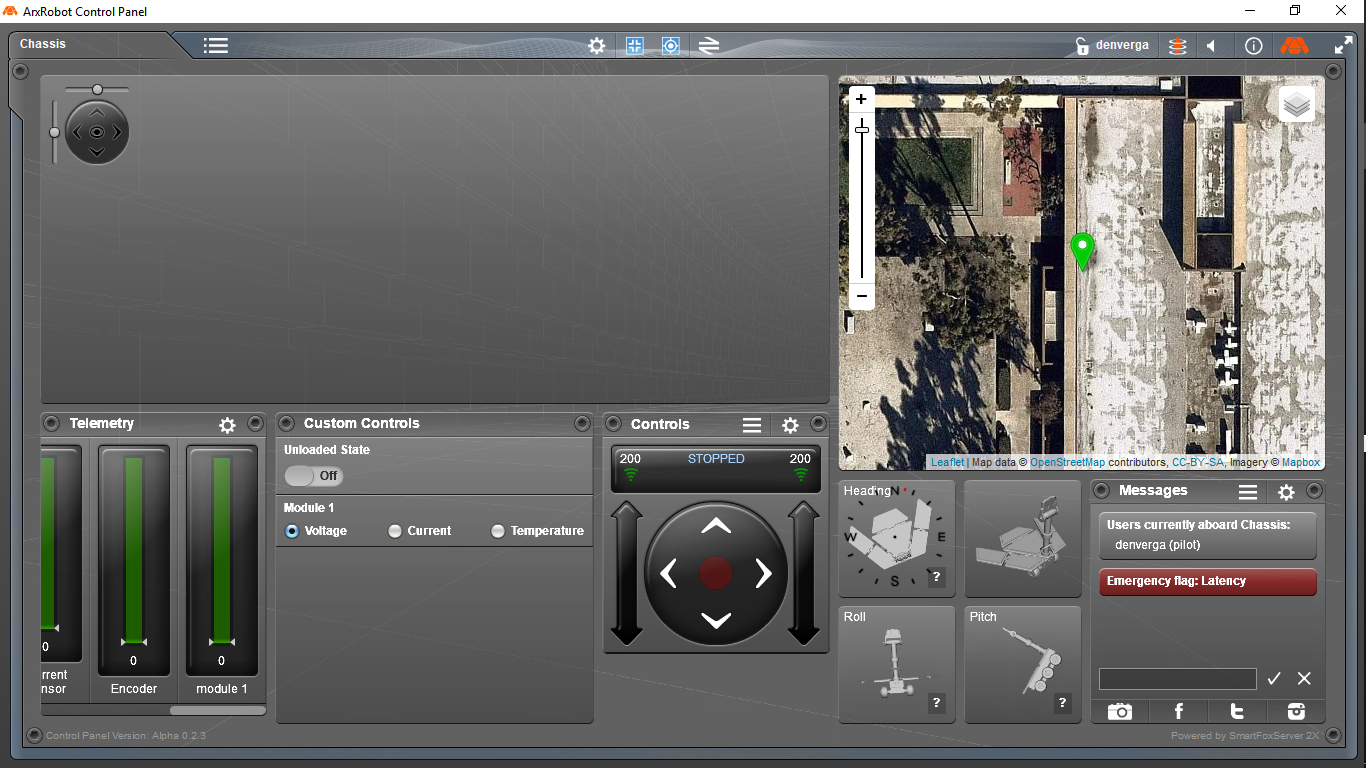
Figure 12. Arxterra Control Panel Continued
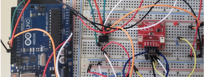
by Wilder Pineda
The objective of the electronic design was to create a distributed network of solar cells that are capable of obtaining the voltage/current/temperature readouts from 16 different solar modules. Each module is comprised of 3 solar cells: 1 active solar cell and 2 passive solar cells connected in series. Modules will be paralleled together in groups of 3 or 5. The solar array will be charging the 12 volt acid battery.
After reviewing the code from the previous iteration (Pathfinder Solar Generation #2), we found that it yielded many errors, so we determined it was not complete. This led us to analyze the PCBs provided by the previous team as well, and we came to a conclusion that their design contained flaws in that the sensors were being powered up by the solar panels and the I2C traces were connected incorrectly. Therefore a new code had to be written from scratch and new PCBs had to be design as well.
by Wilder Pineda
Figure 13 below shows the circuit Schematic for the active panel, figure 2 shows the schematic for the passive panel, and figure 3 shows the schematic of the power hub.
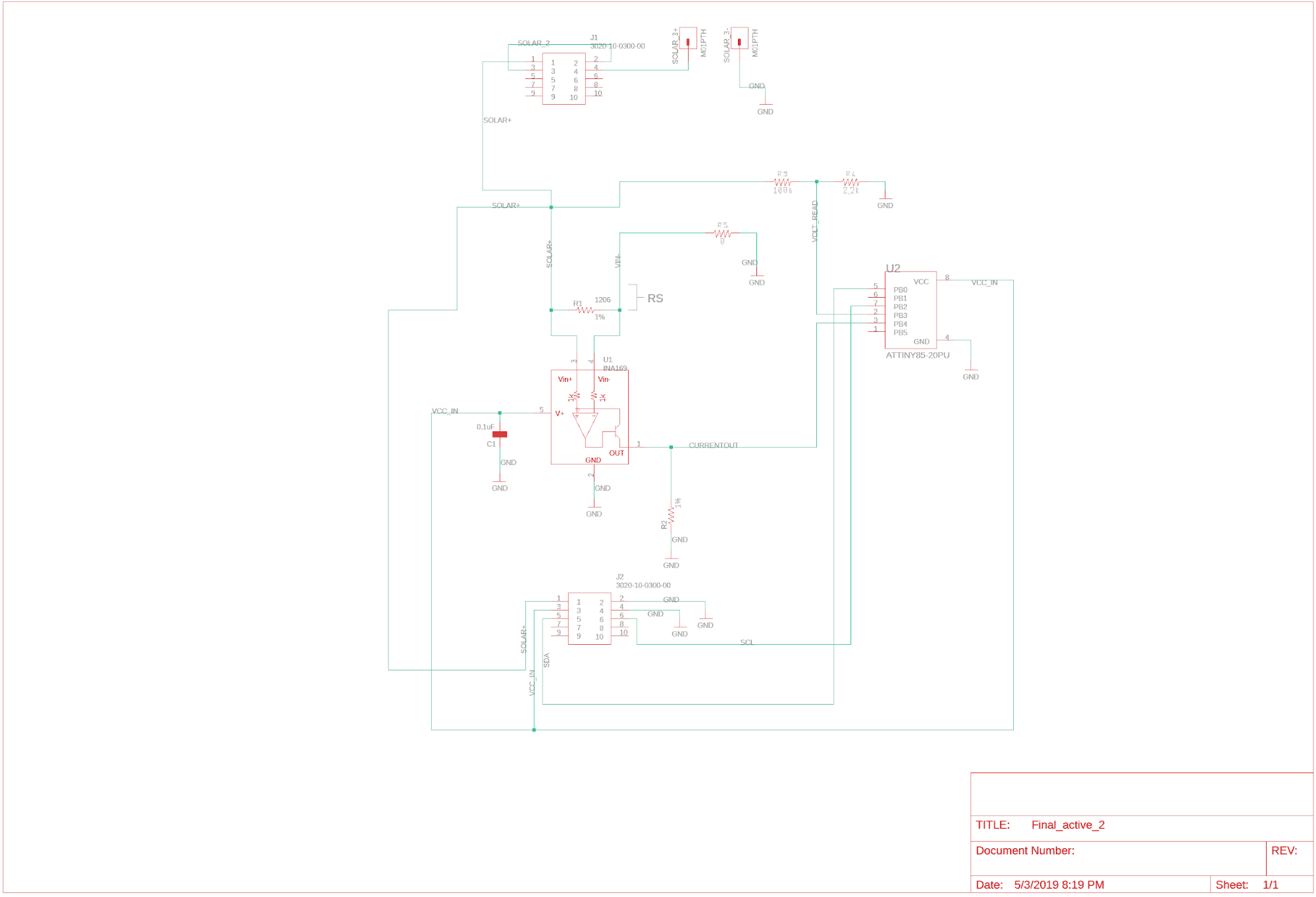
Figure 13. Active Cell Schematic
The purpose of the active panel is to obtain various solar module measurements. We used an ATtiny85 to read the voltage and temperature and an INA169 to read current. This data is sent through the ATtiny85 I2C network using the ribbon connectors.
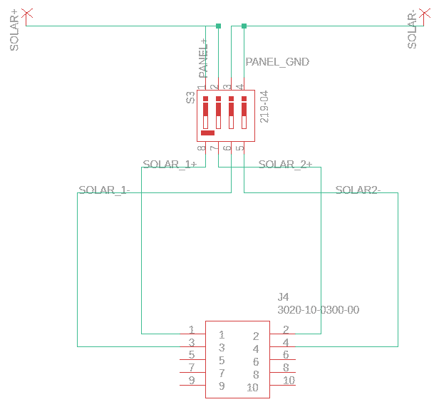
Figure 14. Passive Cell Schematic
The passive PCB, allows us to transfer the power being generated from the solar panel and transfer that power to the Active PCB. The 4 pin dip switch on the passive PCB allows the operator to choose whether it is passive cell 1 or passive cell 2.
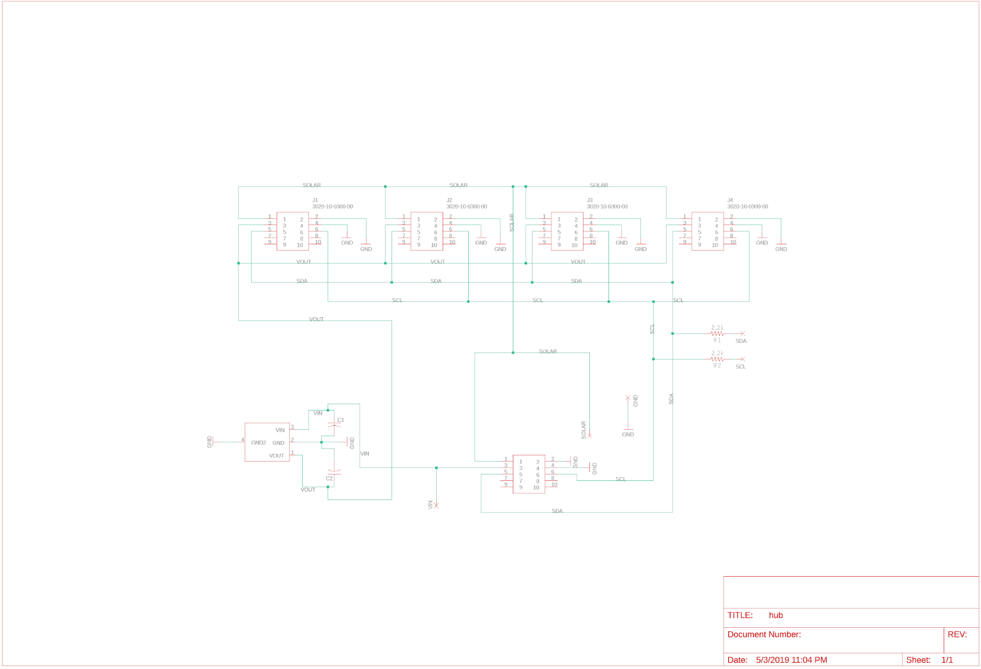
Figure 15. Power Hub Schematic
The power hub is designed to interface the solar array system to the main controller and the battery charger within the Pathfinder chassis. There’s 4 ribbon connectors on one side of the PCB which allows us to connect the solar arrays from each wing (4 in total). The power generated by all solar arrays are paralleled at this point, and then delivered to the battery charger from the 2 single line outputs on the lower end of the board(Solar_GND and Solar+). Telemetry is also collected from all solar arrays via a I2C data bus (these traces are located on the lower end of the board (the name of the traces on the pcb are SCL and SDA which go to the Arduino). The other 2 trace on the lower part of the board (Battery_VIN and Battery_GND) are traces that will have the 6v buck converter lines connected to. These 6V will then reach the LDO (in the middle of the Power hub PCB) and drop the 6V to 5V. These 5V will then be carried out by the 4 connectors on the top of the board, and will be fed to the solar modules, which will then power up the sensors on the active panels.
by Wilder Pineda
Active Cell PCB:

Figure 16. Active Cell EagleCAD PCB Design
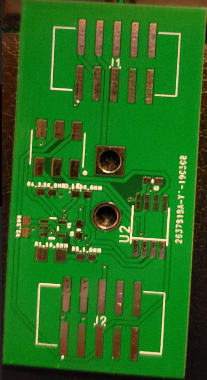
Figure 17. Active Cell PCB
Passive Cell PCB:
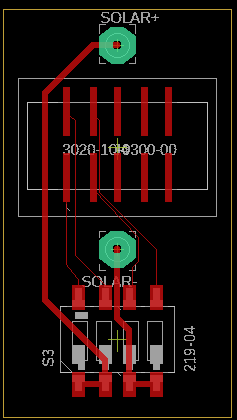
Figure 18. Passive Cell EagleCAD PCB Design
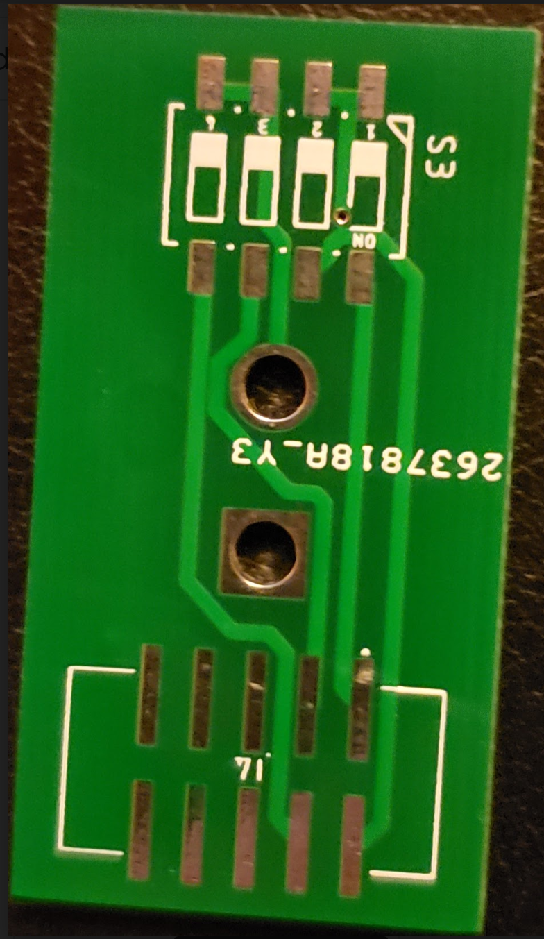
Figure 19. Passive Cell PCB
Power Hub PCB:

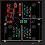
Figure 20. Power Hub EagleCAD PCB Design
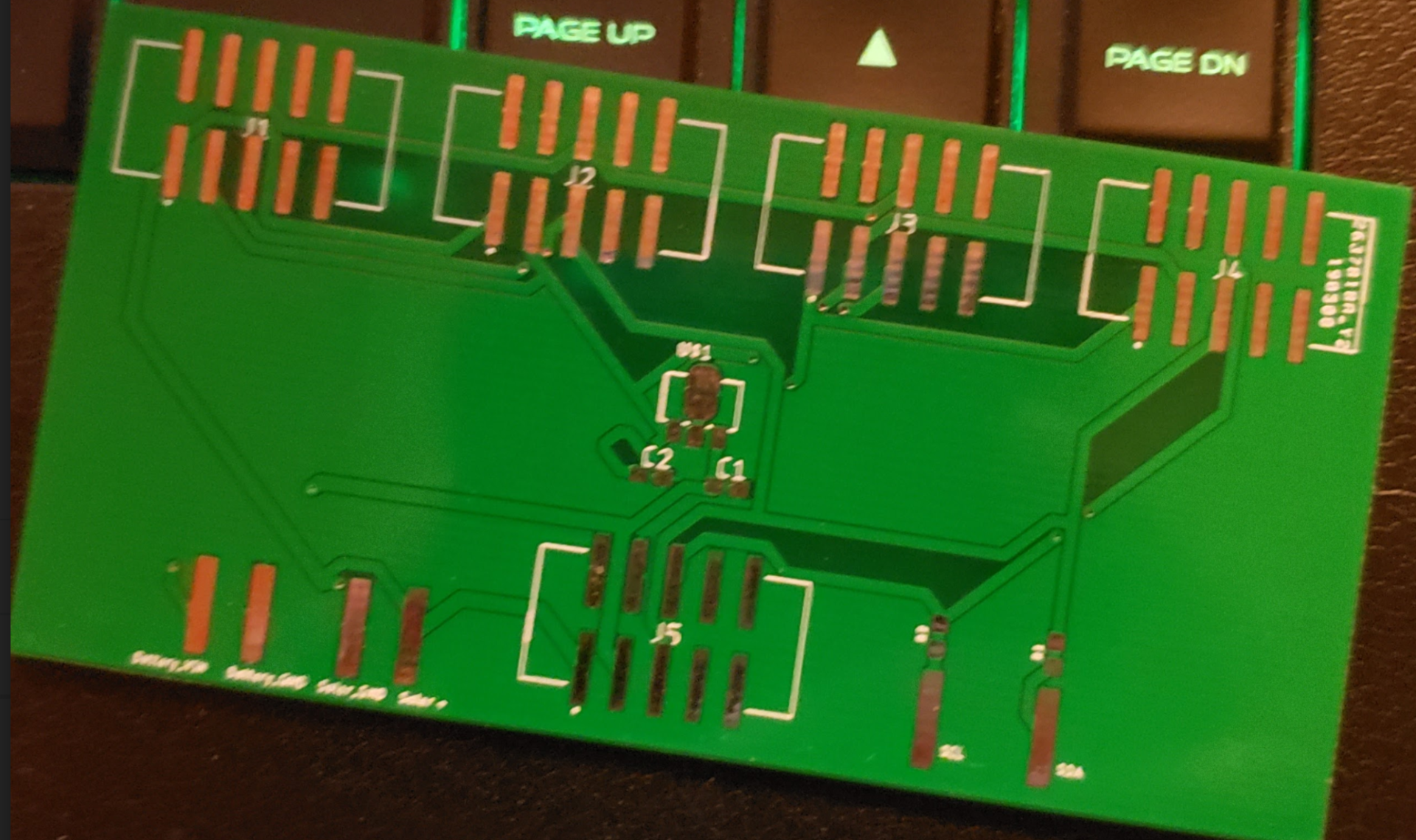
Figure 21. Power Hub PCB
by Wilder Pineda
Two devices were coded, the ATtiny85 (Slave) and the Arduino (Master). The ATtiny85 is programmed to read the analog inputs of voltage, current, and temperature. These bytes will then be sent to the Arduino. The Arduino receives the low and high byte of each voltage/current/temperature, and then combines the low and high bytes into 10 bits. With the 10 bit values, we are then able use specific formulas given in the data sheets of the ATtiny85/INA169 to convert the 10 bit values to their corresponding voltages/currents/temperature.
ATtiny85 code:
The code for the ATtiny85 allows us to obtain analog readouts as and send it via I2C to the Arduino. See the figure below for the working code.
Arduino Code:
The code for the Arduino allows us to obtain the data that is sent from the ATtiny85 via I2C. These bytes are then converted to voltage/current/temperature values. See the figure below for the working code.
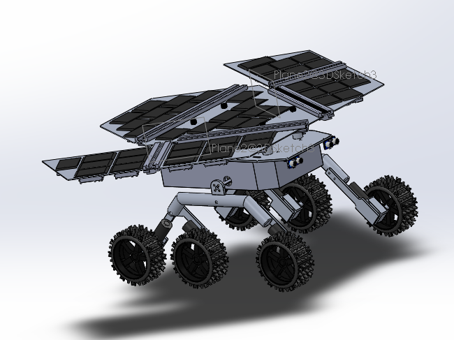
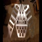
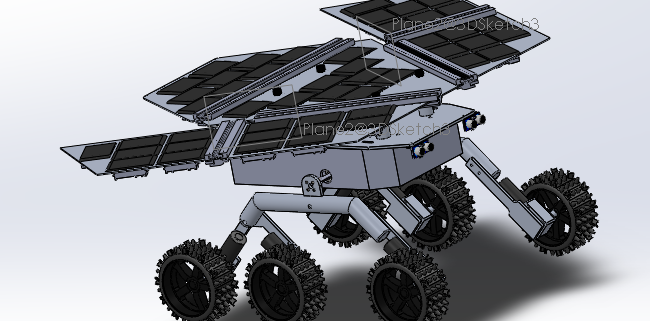
Figure 22. Solidworks model of the fully assembled Pathfinder
By Henry Martinez
The mechanical design revolves around panels, populated with solar cells and custom pcbs, that provides a simple interface between the Solar Array and Chassis. The skeletal structure of the panels are designed to resemble the form factor of JPL’s Spirit and Opportunity rovers. The panels are held together by rubber sheets and aluminium H-channel trims and mounted to the top of the Chassis.
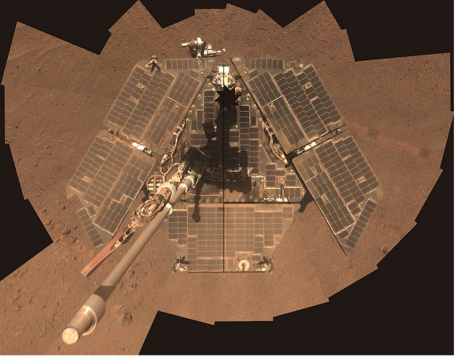
Figure 23. JPLs Spirit and Opportunity Rover Solar Array Layout
by Henry Martinez
The final design is similar to the previous generations minus the linear actuator. The size of the panels allow for the ability, for future generations of the Array, to enter and exit a cocoon state. Due to the customers request, generation 3 focused mainly on the electronic advancement of the project. The Solar Array is comprised of 4 panels: the main panel with dimensions of 444.50mm x 403.8mm x 2.00mm, Tail Panel with dimensions 436.8mm x 209.55mm x 2.00mm, Left Wing, and Right Wing Panels sharing the same dimensions of 723.9mm x 209.55mm x 2.00mm. Solidworks files for the panels were originally supplied by the design and manufacturing engineer from generation 2, however, it was later discovered that the dimensions were incorrect. New panels were constructed using measurements from the panels produced by Pathfinder Solar Generation #1 and verifying the dimensions by producing acrylic models as well as comparing dimensions to an image of JPL’s Spirit Rover.
Each panel will contain square cuts of 55 x 55 mm, where the active and passive solar cells will rest on top of the panel with the custom pcbs floating within the square cuts. The size of the square cuts were determined by the size of PCBs used for the active and passive cells. The cuts are given 5 mm of space between each other to allow enough space for the PCB “ Hat” enclosures. The panels are made in aluminum alloy 6061 as it is a good insulator and light weight. The manufacturing process of the panels were done by Michael Hill at AoSA Image.
by Henry Martinez
The “Hat” style enclosures are used to house the PCBs and secure the solar cells to the supporting panel. The enclosures are also designed with integrated cable management. The ribbon cabling connecting each “hat” is fed through the cable pathway on the side of the “hat” and next to the port. The ribbon connector will secure the solar cell PCBs to the secured ribbon cables, eliminating the need for any mounting system. There are two different types of enclosures, one for each of the different PCBs, active and passive. The main and tail panel will hold 3 solar modules, each module consisting of 1 active cell and 2 passive cells. Each of the wing panels will both hold 5 modules . The enclosures will be glued to the bottom of the panels via silicon adhesive. Each hat is 57 mm x 57 mm giving 2 mm of space for the adhesive, the difference between the passive and active hat is the amount of holes at the top for the different number of connectors.
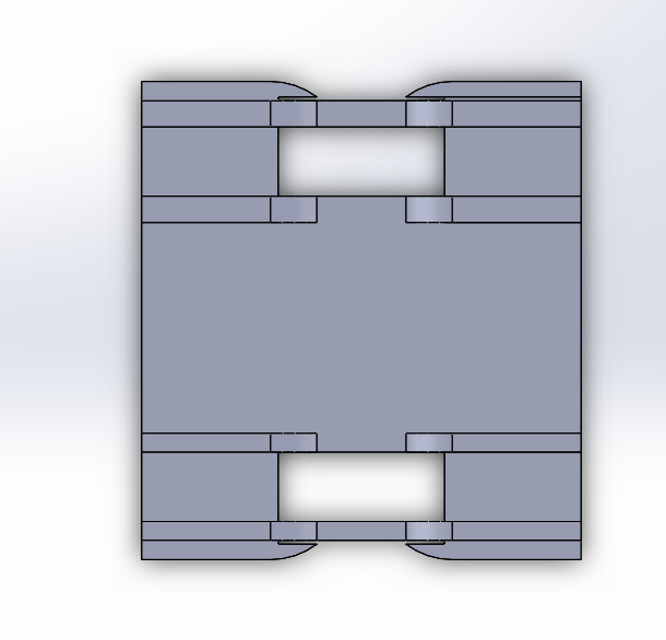
Figure 24. Active PCB Enclosure
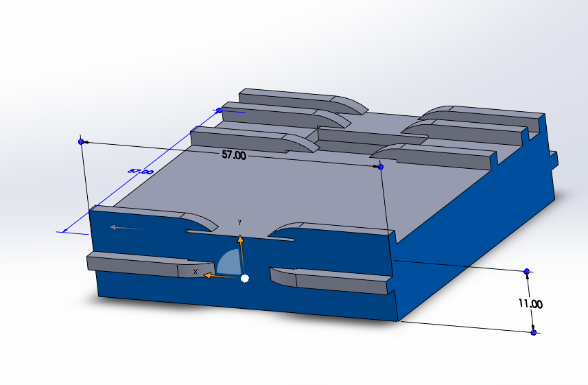
Figure 25. Passive PCB Enclosure
by Henry Martinez
The purpose of the channels is to connect and support each panel in a static position above the chassis. The Main panel supports the other three panels in an open, stationary position by attaching aluminum H-channel trimmings to the edges of the panel. H-channels with a thickness slightly above 2mm could not be found so channels with an inside width of 3.97mm were purchased. A 1 mm rubber lining placed within the channels was used to make up for the extra space. When inserting the panels into the rubber lined channels, we found that the compression created by the rubber was substantial enough to hold the panels in place.
Professor Hill proposed a design for a future iteration that includes a 3D printed channel comprised of three parts: the base, hinge, and attachment channel. The living hinge is made out of flexible tango material and allows for the panels to move in and out of a cocoon state. However, purchasing the aluminum H-channels was viewed as the best option due to printing time constraints.
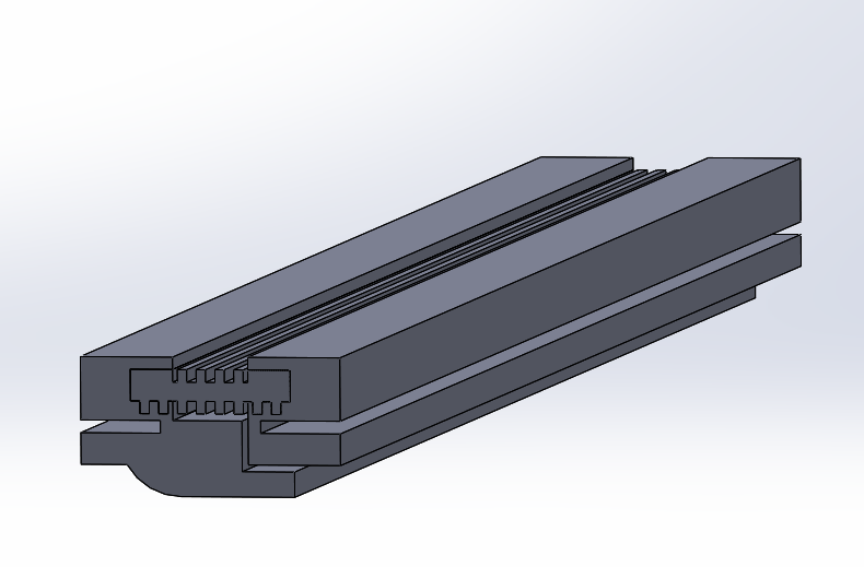
Figure 26. 3-D Printed Channel
by Daniel Enverga
The following is the verification matrix that will be used to verify the requirements. A summary of the test cases and explanations is as follows.
| Requirement Number | Requirement Text | Verification Criteria | Yes | No | Test Cases |
| L1.1 | The Pathfinder solar array system shall follow the form factor of the solar array system found on JPL’s Opportunity & Spirit rovers. | The dimensions of the Pathfinder Solar Array system will share the same ratio to the Solar Array system of the JPL rovers. | 1 | ||
| L1.2 | The Pathfinder solar array system shall be comprised of a series-parallel network of solar array modules, capable of delivering data from at least 2 module. | The solar array system will include 16 modules of 3 cells, spread out between 4 different aluminum panels. | 1,2,3 | ||
| L1.3 | The distributed network of solar cells should continuously charge the Pathfinder’s battery while the vehicle is both operating and not operating. | During non-operation, the solar array will be charging the battery. This will be based on if the initial voltage reading of the battery is lower than the voltage reading of the battery is 5-10 minutes later. | 4 | ||
| L1.4 | The Pathfinder Solar Array shall incorporate custom PCB designs to collect solar module charging data and transmit power from the solar array to the power hub. | The telemetry can be read in real time while the battery is charging | 2,3,4 | ||
| L1.5 | The Pathfinder’s solar array telemetry shall provide real time charging data to the operator. | Comparison between the telemetry on the Arxterra Control Panel and a telemetry read through the arduino panel. | 2,3,4 | ||
| L1.6 | The Pathfinder Solar Array project will employ plastic “hat” enclosures to provide protection to the PCB’s. | The PCBs are enclosed with a plastic hat. | 1 | ||
| L2.1.1 | The solar array system will be comprised of 4 aluminum panels that will support a distributed network of solar modules. | The solar array system will include 16 modules of 3 cells, spread out between 4 different aluminum panels. | 1 | ||
| L2.1.2 | There will be 4 unique panel designs comprising of the Main Panel with dimensions 444.50mm x 426.71mm x 2.00mm, Tail Panel with dimensions 419.1mm x 209.55mm x 2.00mm, Left Wing, and Right Wing Panels sharing the same dimensions of 660.40mm x 201.93mm x 2.00mm | The dimensions of the panels can be measured. | 1 | ||
| L2.1.3 | The main panel shall use screws to fasten onto a baseplate to withstand the shaking of a human to replicate the shaking during movement of rocky terrain. | The measurement of the screws will match the one stated in the requirement | 5 | ||
| L2.1.4 | The main panel shall be capable of supporting x amount of weight with less than x degrees of displacement on the the other three panels in an open, stationary position by attaching aluminum H-Channel trimming to the edges of the main panel. | The tail and both wing panels can be attached to the main panel and kept in a stationary position | 5 | ||
| L2.2.1 | One solar array module will contain 3 solar cells connected in series. | One module will have a connection in series (passive-passive-active) | 1 | ||
| L2.2.2 | The main and tail panels will each contain 3 solar modules connected in parallel. | The modules will be connected between active cells (active-active) | 1 | ||
| L2.2.3 | The right wing and left wing panels will each contain 5 solar modules connected in parallel. | The modules will be connected between active cells (active-active) | 1 | ||
| L2.2.4 | The solar arrays from all 4 panels will be connected in parallel. | The powerhub PCB will verify that the connections between the 4 panels are in parallel | 1 | ||
| L2.3.1 | One solar module shall be capable of providing 15 or more volts to the terminals of the battery charger when placed under normal classroom lights with an unobstructed zenith of 90° | By attaching a voltmeter to the output of the active cell, the voltmeter will read at least 15 V. | 2,3,4 | ||
| L2.3.2 | One solar module shall be capable of providing 0.027 or more amps to the terminals of the battery charger when placed under normal classroom lights with an unobstructed zenith of 90° | By attaching an ammeter to the output of the active cell, the ammeter will read at least 0.05A. | 2,3,4 | ||
| L2.3.3 | The solar array should be capable of recharging the battery from 50% to 60% of its total value in 1.25 hours under sunny conditions with no clouds | After 5 hours of charge time, the battery should be up-to 90% of charge. | 2,3,4 | ||
| L2.4.1 | The solar module will contain three custom PCBs. | 3 separate PCBs will be utilized in total. Power Hub, Active Cell, Passive Cell | 1 | ||
| L2.4.2 | The custom PCB on the active cell in the solar module shall be capable of measuring the voltage through the module | The voltage of each module can be read through the Atiny and INA169 on the active cell | 2,3,4 | ||
| L2.4.3 | The custom PCB on the active cell in the solar module shall be capable of measuring the current through the module. | The current of each module can be read through the Atiny and INA169 on the active cell | 2,3,4 | ||
| L2.4.4 | The custom PCB on the active cell in the solar module should be capable of measuring the temperature through the module. | The Temperature of each module can be read through the Atiny and INA169 on the active cell | 2,3,4 | ||
| L2.4.5 | The active cell in the solar module shall contain a custom PCB capable of summing currents from at least 2 modules in parallel. | The active cell that will attach to the power hub will be able to read the data from all other active cells | 2,3,4 | ||
| L2.4.6 | The Power Hub shall contain a custom PCB shall be capable of summing at least 2 solar array currents in parallel. | The power hub will be able to sum together the currents of the main panel, tail panel, and both wing panels | 2,3,4 | ||
| L2.4.7 | The active and passive cell PCB designs will employ 10-pin, ribbon cables and ribbon cable connectors as the preferred method of transmitting power. | The connecting cable between passive-passive and passive-active will use a ribbon cable. | 1 | ||
| L2.5.1 | The Arxterra control panel shall display operational voltage and current values of 4 modules situated on the Pathfinder’s solar panels. | The Arxterra Control Panel correctly shows the telemetry from each module using the select custom command | 4 | ||
| L2.5.2 | The Arxterra control panel shall display the total operational voltage and current of the distributed network being delivered to the terminals of the battery charger. | The default Arxterra Control Panel select command for telemetry would display significantly higher data compared to the other selects. This data would be read as the sums of all the modules | 4 | ||
| L2.5.3 | The Arduino MEGA situated within the chassis will employ “I2C” communication protocol to relay telemetric values from the Pathfinder’s Solar Panels | The I2C connection pins on the Arduino Mega (Pin 20 and 21) are attached to the Solar Array system. The Arxterra Control Panel also displays the telemetry. | 1,4 | ||
| L2.6.1 | All PCBs will be housed in an enclosure on the underside of the solar array panels and protected from direct contact of debris ejected from rocky terrain | The PCBs are enclosed with a plastic hat. | 1 | ||
| L2.6.2 | Loose cabling will be managed with built-in “seatbelts” in the PCB enclosures. | The seatbelts are used to hold the wires | 1 | ||
| L2.6.3 | The PCB “hat” enclosures will be manufactured out of high-heat resistant material. | The plastic does not melt while the solar panels are in use. | 1 |
By Wilder Pineda, Henry Martinez, and Daniel Enverga
Electronic Design Considerations:
Design and Manufacturing Considerations:
Mission Command and Control Considerations:
Generation 2 Final Blog Post : Gen 2 Final Blog Post
CSULB Innovation Space: Innovation Space
SolidWorks Files: Solidworks Files
Attiny85 Code:ATtiny85 Code
Arduino Code:Arduino Code
INA219 Code:INA219 Code
JPL Spirit Rover Image: JPL Spirit Rover