
Spring 2018: Biped Micro FOBO Final Blog Post
By: Miguel Gonzalez (Project Manager)
Approved By: Miguel Garcia (Quality Assurance)
BiPed Team:
Miguel Gonzalez (Project Manager)
Jeffery De La Cruz (MST)
Jorge Hernandez (E&C)
Table of Contents
Mission Objective
By: Miguel Gonzalez (Project Manager)
Goal for this project is to design and manufacture a BiPed Robot. This robot will be slightly similar to the BiPed robot that was created in Spring 2016 and another bipedal robot named FOBO, created by Jonathan Dowdall. Our design will be based on FOBO but will be much smaller in size that implements micro servos for walking and turning. For sensing its surroundings, the robot will utilize ultrasonic and Infrared sensors. Other key differences between the FOBO and our micro version of FOBO are that:
- The head of our robot shall house a 3DoT board, servos controller shield, and a sensor shield.
- The movement of our robot will be conducted via SG90 micro servos that will replace the clunky and oversized Hitec HS-805BB servos.
- The legs of our robot will have a more efficient method to mount and utilize its servos for weight reduction and for longer walking steps.
- Our robot will utilize Bluetooth technology for user to robot communication and movement control
- The robot’s power system will be changed from heavy LIPO batteries to a single Samsung 18650 battery located near the robot’s center of mass.
The mission of Project BiPed is to design the BiPed to navigate a predesigned maze. The BiPed shall be able to navigate the maze with user input from the Arxterra App/Control Panel. The BiPed will be able to memorize the user-defined path and will be able to navigate it autonomously. In addition, the BiPed will acknowledge other robots while traversing the maze and avoid collisions using its sensors. To learn more about the mission objective you can take a look here. For preliminary maze designs and definitions take a look here.
Project: Level 1 Requirements
By: Jeffery De La Cruz (MST Engineer)
Verified By: Miguel Gonzalez (Project Manager)
Will:
L1-1: Micro FOBO will stand on its own without any physical help.
L1-2: Micro FOBO’s electronic components will be easily assembled and disassembled.
L1-3: Micro FOBO will have 2 legs.
L1-4: Micro FOBO will be a toy robot based on the design of the FOBO by Jonathan Dowdall.
L1-6: Micro FOBO will fit within the classroom cabinets shelves. 28”x13”x14.5”
L1-7: Micro FOBO will utilize a 3DoT board or Sparkfun Pro Micro 3.3V/8MHz.
L1-8: Micro FOBO’s part components will be 3D printed using the material carbon fiber PLA.
L1-9: Micro FOBO will not exceed a print time of 7.80 hours. Upon approval of the waiver.
Shall:
L1-10: Micro FOBO shall not exceed a cost of $250 to construct.
L1-11: Micro FOBO shall be 60% or less of the overall size of Jonathan Dowdall’s FOBO
L1-12: Micro FOBO shall detect intersections in the maze.
L1-13: Micro FOBO shall be able to perform static walking.
L1-14: Micro FOBO shall produce 90 degrees turn.
L1-15: Micro FOBO shall be guided through the maze with the use of the Arxterra application.
L1-16: Micro FOBO shall record the path of the maze.
L1-17: The Micro FOBO shall traverse the maze using the recorded path.
L1-18: Micro FOBO shall be able to traverse cloth, paper, and linoleum materials.
L1-19: The Final Biped shall be completed by May 10th, 2018.
Should:
L1-20: Micro FOBO should step over a square rod 1cm tall, 1 cm wide by 10 cm long
L1-21: Micro FOBO should be able to perform dynamic walking
System/Subsystem: Level 2 Requirements
By: Jeffery De La Cruz (MST Engineer)
Verified By: Miguel Gonzalez (Project Manager)
Will:
L2-1: Micro FOBO will be connected via Bluetooth to the app on an android phone.
L2-2: Micro FOBO dimensions of the robot will need to be small enough to fit in a 4in by 4in box for maze purposes.
L2-3: Micro FOBO will use SG90 micro servos.
Shall:
L2-4: Micro FOBO shall use UV/IR sensors to detect intersections.
L2-5: Micro FOBO shall use the color of the maze to establish if it needs to turn. black (0,0,0) green (0,255,0) for line following.
L2-6: Micro FOBO shall use a battery that outputs 3.7V nominal.
L2-7: The user shall use the Arxterra application to move the robot forward, backward, left, and right.
L2-8: Micro FOBO connectors shall be able to connect and reconnect all the wiring in less than 10 min.
L2-9: Micro FOBO wiring shall be nice and clean with the use of terminal blocks, contact pins, 2.0mm PH series JST connectors, and barrel connectors.
L2-10: Micro FOBO shall play a musical tune when the maze is completed.
L2-11: Micro FOBO shall have indicating LEDs to demonstrate either a left or right turn.
L2-12: The Micro FOBO shall record the path of the robot on the 3DoT board or the Sparkfun Pro Micro 3.3V/8MHz to navigate the robot through the maze.
L2-13: Micro FOBO shall use a 3D printed chassis and leg components.
L2-14: Micro FOBO shall measure within 4.5” x 3.25” x 7.25”.
L2-15: Micro FOBO shall weigh no more than the allocated mass of 460g.
L2-16: Micro FOBO shall detect objects 8 inches from it.
Should:
L2-17: Micro FOBO should be able to see other robots to avoid a collision. The robot will stop completely and wait for clearance. (Ultrasonic sensor)
L2-18: Micro FOBO should take a bow at the end of the maze as a victory celebration.
System Block Diagram
By: Jorge Hernandez (E&C Engineer)
Verified By: Miguel Gonzalez (Project Manager)
After looking at all the constraints and requirements for the robot our group came up with a system block diagram that could help us visualize how the robot’s components interacted with one another. This diagram made it clear to understand where initial designs should be made and provided great insists on some challenges we would have in the future. Below we link the blog post to the system block diagram the group made.
Work Breakdown Structure
By: Miguel Gonzalez (Project Manager & Manufacture)
When working on a team project it’s important to break down the project into general tasks and assign them to team members. Typically a chart is created to easily visualize how the work is divided among team members, this called a WBS (Work Breakdown Structure). Here we link to our post demonstrating and explaining our WBS.
Product Breakdown Structure
By: Jeffery De La Cruz (MST Engineer)
Verified By: Miguel Gonzalez (Project Manager)
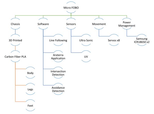
Fig.1 Product Breakdown Structure
Based on System Block
Sensor Suite
- The color sensor will be able to detect colors and its data input range Ex, black (0,0,0) green (0,255,0) for line following.
- Will be able to see intersection sign on the maze and differentiate its color from the path lines.
- Shall be able to see other robots to avoid a collision. The robot will stop completely and wait for a command. (Ultrasonic sensor/IR)
- The robot should have to indicate LEDs to show where the robot plans to make a turn (left or right)
Smartphone App
- Will allow usage of the app to navigate the robot through the maze through forward, back, left, and right commands.
- Will record the path of the robot in 3Dot board to navigate robot without the user controlling it.
- The robot will be connected via Bluetooth to the app on an android phone.
Chassis
- The wiring for the robot shall be nice and clean with the use of terminal blocks, contact pins, 2.0mm PH series JST connectors, and barrel connectors.
- All connectors shall be able to connect and reconnect all the wiring in less than 5 min.
- Dimensions of the robot will need to be small enough to fit in a 6in by 6in box for maze purposes.
Battery
- The robot power management system will use two 1000mAh 2S 20C Lipo Pack rechargeable LIPO batteries.
Interface Matrix
By: Jeffery De La Cruz (MST Engineer)
Verified By: Miguel Gonzalez (Project Manager)
After verifying the product breakdown structure we began listing the interfaces for the 3DoT Board that were going to connect to our sensors and motors.
Prototype Fritzing Diagram for Biped
By: Jorge Hernandez (E&C Engineer)
Verified By: Miguel Gonzalez (Project Manager)
With the product breakdown structure and the interface matrix completed we began the prototyping the circuit and making connections to the servos and sensors. The Fritzing application allows a physical breadboard design to be created digitally. By designing a digital version, and verifying its functionality we can have a smooth transition to creating the PCB.
Mechanical Drawings
By: Miguel Gonzalez (Project Manager & Manufacture)
This blog demonstrates the process of developing all the parts for the Micro Fobo and the unique ways we solved issues throughout the building process.
Resource Reports (Power, Mass, Cost)
By: Jeffery De La Cruz (MST Engineer) and Miguel Gonzalez (Project Manager and Manufacturing )
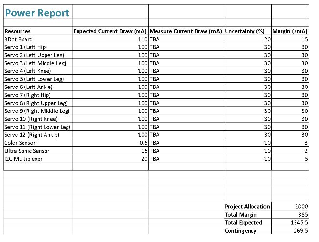
Fig.2 Power Report

Fig.3 Finding the Center of Mass
Summary of Experiments / Rapid Prototyping Completed and Software Tests
By: Miguel Gonzalez (Project Manager & Manufacture)
It has been approximately eight weeks since the start of the semester and most of the first month consisted of mainly research and write-ups. But after the first month, we began experimenting with small components and sections of our BiPed. We started by looking at the legs of our robot as we knew that making the robot walk on two legs was a crucial part of our design. We created a copy of the 2016 Fall ROFI design and just focused on the legs of that robot. This initial design consisted of having 6 servo motors operating the leg and foot. Using the blog post on that robot and using help from projectbiped.com we were quick to get the robot’s leg to move. If you would like to see images and videos of the robot when it’s operating, you can view our drive folder here. In this configuration, the robot’s leg is very robust and can do very intricate movements while maintaining the robots balance. The issue with this design is that nearly 70 percent of all the weight of the robot consists of the legs alone. We knew that if we can decrease the weight on the robot we could have easier walking movements that in theory can speed up its walking speed. Our secondary design for the robot was to reduce the number of servos operating on the legs by only having four servo motors instead of six.
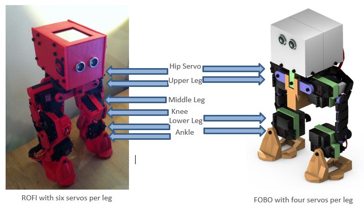
Fig.4 ROFI vs FOBO
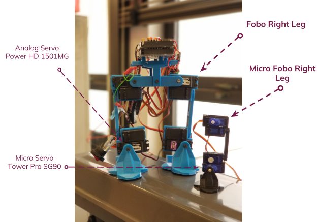
Fig.5 Original Size vs Micro Size
This newer design would remove both the knee servo and middle leg servo on both legs. Theoretically, the newer design should remain functional and provide the ability to take longer strides when walking. It is important to note that the designs for the new leg designs have been modeled and 3D printed but the test will take place on March 17, 2018. This experiment will allow us to verify that the legs can perform walking movement and maintain a higher walking speed than the six-servo design.
Concluding Thoughts
Resources
Project Video: YouTube
PDR: EE400D Design Presentations
Project Libre Excel: Burndown
Verification and Validation Documents: https://www.arxterra.com/spring-2018-project-biped-verification-and-validation-pass-fail-matrix/
Solidworks Files: Micro FOBO
Fritzing Files: Fritzing-20180331T202552Z-001
EagleCAD files (zip folder): Copy of EagleLibraries | 400-D gerber-20180518T192139Z-001 | ServoShield2Eagle-20180518T192149Z-001
Arduino and/or C++ Code: Walking and Turning | Remote_Control FOBO
Bill of Materials: https://www.arxterra.com/spring-2018-biped-preliminary-budget/ Budget Table pdf
3D print Time: https://www.arxterra.com/spring-2018-biped-3d-print-time/
List of all our blog post: https://www.arxterra.com/news-and-events/members/3dot-robots/biped-generations/biped-generation-5/

Final Arduino Code
By: Jordan Smallwood (Project Manager)
Approved By: Miguel Garcia (Quality Assurance)
Table of Contents
6-Wheel Differential:
The six-wheel differential takes advantage of pin-change interrupts since most of the external interrupt pins are lodged within communication pins on the ATMega 2560. The way it works can be viewed here. Currently we are experiencing difficulties getting the software to work, this may be due to the short that took place while wiring the Pathfinder up. I believe there may be some issues with the motor drivers and we will have to replace these. The code for a 6-wheel differential can be found here: Final Arduino Code.
No-Load:
In order to preserve energy in the wastelands of Mars, we need to cut off power to motors that are spinning freely. In order to determine if a wheel is spinning freely we compared the current power running to them with known values of no-load current and would turn them off if need be. Turning off the motors is not an issue but it’s determining when to turn them back on that poses a threat. We can pulse the motors to find out if a load is present but at that point it may be too late and will create unnecessary drag on the system. Further studies can be found here. If you would like to view the code it is included in the .zip folder mentioned in the previous section.
Due to time constraints and non-software related issues, the Pathfinder is currently unable to perform GPS navigation. However, access to GPS information regarding latitude, longitude and heading can be extracted from the Arxrobot application onto the Arduino. Furthermore, these values can be modified to produce distance to checkpoints and required turn. Although this feature is currently not functional it is definitely feasible.
Conclusion
Acting as Project Manager/Software was an extremely difficult task this semester. I would have liked to focus on one specific area, specifically software, so that I could have done more as far as coding went. But will have to continue working on this code throughout the summer so that Pathfinder will be able to complete it’s mission.
References
