Fall 2016 Solar Panels: Choosing Panel Thickness (Stress Tests)
By Ridwan Maassarani (Design & Manufacturing)
Edited and Approved By Inna Echual (Project Manager)
Objective: The thickness of our panels must be carefully chosen as “too large” of a thickness could result in additional weight, possibly causing unnecessary strain and bending. Though the chassis could withstand our panels weight a maximum 50 lbs (as stated by the chassis group), we would like to chose a weight that would minimize bending as bending could cause our solar cells to break due to their delicate state.
Choosing Optimal Thickness
The thickness of the panels should be chosen so that it can carry its own weight under the force of gravity, as well as be well below the maximum 50 lbs. load requirement set by the chassis group. Cutting various panel configuration numerous times using varying aluminum thicknesses would take a long time and waste expensive material, the stress analysis tool feature in SolidWorks was used.

Figure 1: Panel Reference
The panel being evaluated is the butt panel (see Figure 1). The stress analysis tool was used on the butt panel to verify that it wouldn’t bend under the force of gravity.
The first step is to define a location where the object being tested will not move. In my case, it is three mounting holes for the hinge. Gravity acting on the top of the back panel was defined as the load. Using the mass properties tool under evaluate in SolidWorks, the approximate mass of the back panel was obtained to be 383.93 grams.
Note that the additional of the cells, rubber sheets, and glass will increase the weight; to remedy this, the weight of a single cell was measured and multiplied with the amount of cells that can fit onto the back panel.

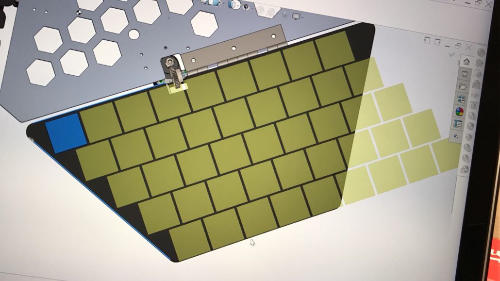
Figure 2: Solar Cell Arrangement on Butt Panel
Currently, 33 cells can fit on the butt panel comfortably with 2mm spacing between them (also taking into account panel cutouts for the gears, see Figure 2 above). The weight of one cell was measured to be 0.75 grams so an approximate addition of 24.75 grams is added due to cells. Masses pertaining to the solder and copper tape is negligible but the cell system was rounded to 30 grams.
The total mass was converted to Newtons, which was entered into one of the SimulationXpress analysis wizard. Since aluminum was determined to be the material of our panels, it was selected in the design.
Figure 3: Butt Panel Displacement using 3.175mm Aluminum
Figure 3 shows the displacement acting on the panel. An eDrawing file can be saved once the results have been calculated. Furthermore, the tool can be used to optimize the design. For example, it allows the user to change dimension right and set goals to meet the customer’s needs. SolidWorks will calculate multiple scenarios to meet specific goals.

Table 1: Base to Butt Panel Deflection Data

Graph 1: Thickness (mm) vs. Deflection (mm) of Butt Panel
Data concerning deflection was generated and inputted on Excel in order to determine panel thickness unacceptable deflection is seen. Table 1 shows the deflection from the base panel to the butt panel. The relationship between the varying thicknesses and resulting deflection is shown in Graph 1. The x-axis shows different thicknesses of 6061-T6 aluminum in millimeters and the y-axis represents the deflection distance in millimeters.
The four side panels (left front, left back, right front, right back) are similar in size and weight so the same stress analysis was done on the deflection between the base panel and the right front panel. Figure 4 shows the displacement acting on the aforementioned panel.
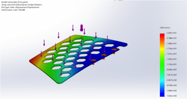
Figure 4: Right Front Panel Displacement using 3.175mm Aluminum
Figure 4 shows the deflection between the base and right front panel. Table 2 and Graph 2 contain the data on the relationship between thickness and deflection distance, as done with the butt panel.
Conclusion
Based on the data, we were able to determine that 1.25 in (3.175 mm) is the optimal thickness our aluminum should be to minimize bending. Our motors will be able to handle this weight and the total weight (including the addition of cells, wires, glass, motors, etc.) is still under the weight restriction of 50 lbs as set by the chassis group.