Pick and Place – Updated Requirements and Mass Reports
By: Chastin Realubit (Missions Systems and Testing)
Level 2 Requirements:
- L2-1: Attached compartments shall not interfere with the functionality of the machine.
- L2-1a: Wires shall be shielded or incorporate heat shrinks in all areas of the pick and place machine.
- L2-1b: The RJ-25 cables shall be able to reach every operable part of the aluminum picking surface, while maintaining a standard of bend radii of 2 inches to prevent fatigue while running.
- L2-1c: All microcontrollers, shields, electronics, and precision sensitive running gear shall be isolated from vibrational or other outside disturbances.
- L2-1d: Compartments to house, wires, electronics, pumps, tape, and accessories will not occupy more space than half a foldable table.
- L2-1e: The legs of the machine will be raised so that the cabinet can be placed.
- L2-1f: The cabinet shall be used to hide the hardware (i.e. vacuum, Arduino, etc).
- L2-1g: The cabinet should be formed using vacuform to make the machine look neat and professional.
- L2-1h: The legs of the machine will enclosed with a material that can reduce the vibration of the machine to make it more accurate.
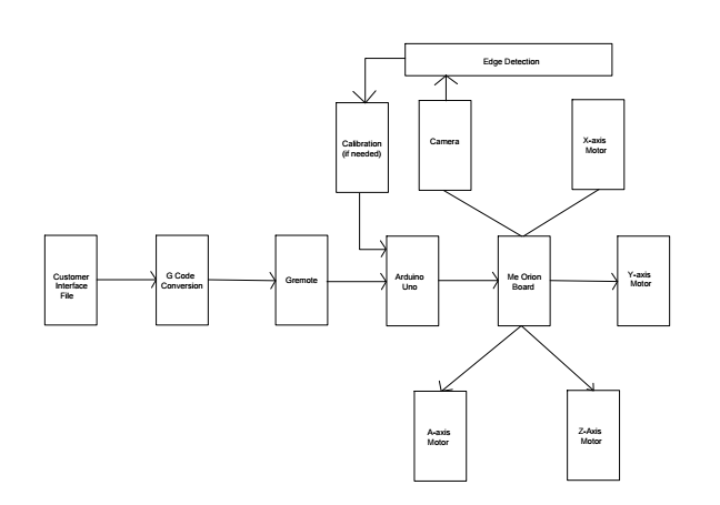
- L2-2: The camera of the pick and place shall be used to incorporate edge detection technology (used as an alignment camera, the same as the Madell Pick and Place).
- L2-2a: Pick and place shall incorporate edge detection to determine origins
- L2-2b: Pick and place will have dedicated Arduino for camera system
- L2-3: The Pick and Place will include video tutorial, written manual, sample test files.
- L2-3a: Pick and place shall have detailed instructions on how to operate the machine through the software
- L2-3b: Pick and place will incorporate LCD to make machine more user-friendly (Display status, component being placed etc.)
- L2-3c: The user will be able to interface with the machine, and control the machine with an emergency power button.
- L2-3d: The user manual should include a video to guide users on how to use it. (The video will show step by step how the user will interface with the GUI, where to download all software, and how to turn gerber file into cnc file.)
- L2-3e: The manual will include a troubleshooting section that will help users fix the machine in case hardware was accidentally disconnected.
- L2-4: The case should enclose the machine, and hold its weight in a manner of minimal movement when carrying.
- L2-4a: The pick and place should be remained locked and secure to it location of setup.
- L2-5: The machine shall be faster than human production time of 4 Hours.
- L2-5a: Pick and place will incorporate the addition of eight additional servos
- L2-5b: All part tape shall be managed and hassle free throughout the entire operational procedure of the machine.
- L2-5c: All parts needed to create a 3DoT board shall be able to be picked and placed within tolerances of + or – 0.2mm.
Mass Report
| Vacuum System Components | Preliminary Mass (g) | Uncertainty (%) | Margin (±g) | Expected Mass (g) | Actual Mass (g) |
| Stepper Motor (A-Axis) | 245.00 | 5% | 12.25 | 245.00 | 247 |
| Stepper Motor (Z-Axis) | 245.00 | 5% | 12.25 | 245.00 | 246 |
| Vacuum Nozzle | 2 | 5% | .1 | 2 | TBA |
| Z-Axis Actuator | 292.00 | 5% | 14.6 | 300 | 244.12 |
| Detection Camera | 3 | 5% | .15 | 3 | TBA |
| Project Allocation | Experiment: The Z-Axis motor can still function after attaching 2000g as a load.
The vacuum will still need to be experimented on to see how much load can be placed on it. So our preliminary allocation is 2000g |
||||
| Total Expected Mass | 795 g | ||||
| Total Margin | 39.35 g | ||||
| Total Actual Mass | TBA | ||||
| Contingency | 1165.65 g | ||||
Experiment:
Z-Axis Motor: We did an experiment to see the load that the Z-Axis can handle and we found that it will still carry up to 2000 g. This experiment was done so that we can see if the motor can still move up and down even with more load. This was needed because we are adding a camera on the Z-Axis and we needed the system to still function with extra weight.
Next steps:
We will now need to test the suction of the pump to check if it can carry the ICs that the 3Dot will require of us.
Power Report
| Components | Expected Current Draw (A) | Uncertainty (%) | Margin (±A) | Measured Current Draw(A) | |
| Stepper Motor (X-Axis) | 1.35 | 5% | .0675 | ||
| Stepper Motor (Y-Axis) | 1.35 | 5% | .0675 | ||
| Stepper Motor (Z-Axis) | 1.35 | 5% | .0675 | ||
| Stepper Motor (A-Axis) | 1.35 | 5% | .0675 | ||
| Detection Camera | .75 | 5% | .0375 | ||
| Display Screen | .75 | 5% | .0375 | ||
| Servo fs90r (12) | .3 | .05 | .015 | ||
| Project Allocation | 6 A (Calculated knowing that we will be using two Arduinos with separate power supplies) | ||||
| Total Expected Current | 3.15 A (The motors and servos will not run simultaneously) | ||||
| Total Margin | .36 A | ||||
| Contingency | 2.49 A | ||||