Spring 2016 Pathfinder: Design and Manufacturing – PCB Layout
By:
Lindsay Levanas (Design and Manufacturing)
Table of Contents
Introduction
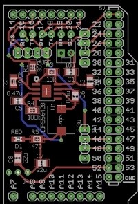
This report will serve to document how the Spring 2016 Pathfinder’s PCB layout was designed in EAGLE7.5.0 Light. Reference to the PCB schematic outlined in Spring 2016 Pathfinder: PCB System Schematic1 will be mentioned, as well as safety precautions from outside sources. Note that all components will be surface mounted, and all jumper pins will be through hole.
Reference – PCB Schematic
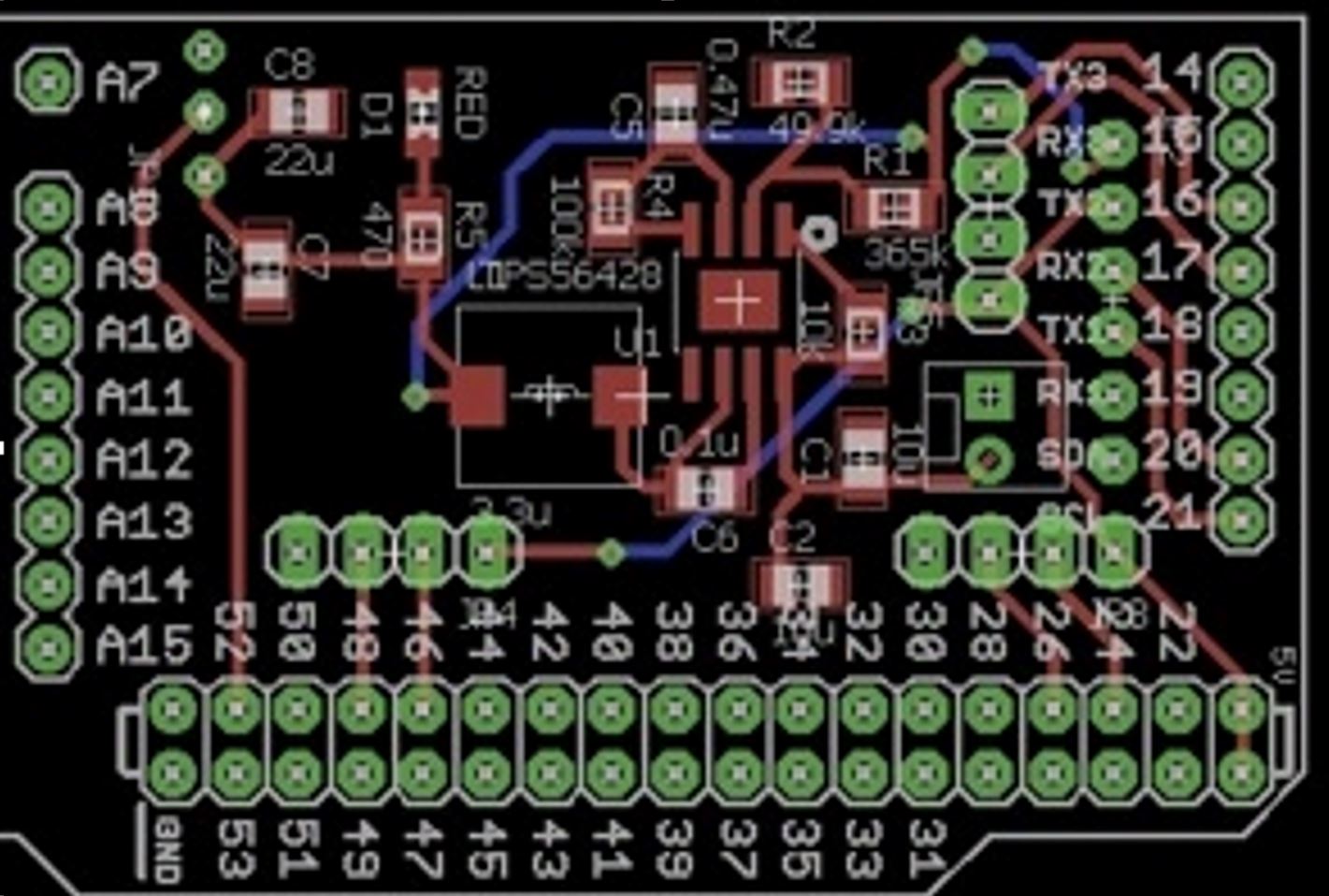
Although Eagle is designed to carry over the component’s wiring from the schematic to the board’s layout (then called airwires), the connections between pins can sometimes be hard to see. For example, in the illustration below, where does the top airwire (the thin yellow line) go? Does it connect straight to the bottom pin of JP4? Or does it connect to one of JP4’s other pins too?
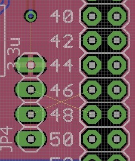
Therefore, in addition to rotating the part (which can be hard to keep track of), the original schematic can also be referenced to verify that the proper connections are being made.
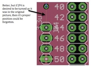
Using the above part as an example, the equivalent part in the schematic can then be used as a reference.
Since pins 2 and 3 are accounted for with single connections and ground does not use an airwire, the top connection can then only be to pin 1.
Note that this process can be used for any component where the connection seems unclear. Now that a general idea has been obtained for the PCB’s wiring, safely measures can be looked into next.
Safety – Current Amount and Trace Width
To ensure that the PCB is able to function properly, the amount of current through the circuit needs to be considered. If the traces are too small for the amount of current they need to carry, then they run the danger of burning out.2 According to the Power Test3 the max amount of current Spring 2016 Pathfinder’s PCB will be carrying is 140mA.
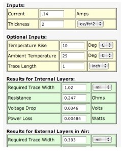
Using a trace width calculator (shows above) for PCBs,4 the minimum desired trace width can be found.
Note that as Spring 2016 Pathfinder’s PCB traces will be on external layers, the width of the trace needs to be no smaller then .393mils.
To check the trace width in Eagle, right click on any trace and select Properties. In the pop up box, check the width number against the grid units. This will tell you what units the width is being measured in as Eagle bases all numbers on the grid units.
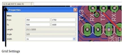
As is illustrated above, the traces are set to have a width of 16mils. As this is larger then the trace width calculations, the trace sizes do not have to be changed.
Alignment – Buck Converter
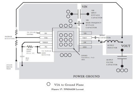
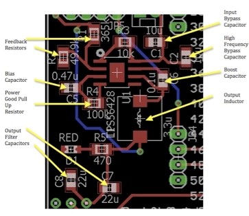
For optimal functionality of the buck converter, the TPS56428 chip needs to be considered. This means that the circuit layout included in the chip’s datasheet5 must be followed, or the PCB may not work. Below is the proper setup outlined in the datasheet followed by the corresponding PCB layout.
Conclusion and Future Plans
In conclusion, Spring 2016 Pathfinder’s PCB will follow the corresponding PCB schematic, current safety precautions and proper chip layout. After fabrication, the next step will be to solder all of the parts onto the board.
Source Materials:
- Spring 2016 Pathfinder: PCB System Schematic, Custom PCB Schematic, 1/3/2016 http://arxterra.com/spring-2016-pathfinder-pcb-system-schematic/
- Reference Designer Calculations, PCB Trace Width Calculator, 2009 http://www.referencedesigner.com/cal/cal_06.php
- Spring 2016 Pathfinder: PCB System Schematic, Power Test, 1/3/2016 http://arxterra.com/spring-2016-pathfinder-pcb-system-schematic/
- PCB Printed Circuit Board File Creation Calculator, Trace Width Website Calculator, 2007 http://www.4pcb.com/trace-width-calculator.html
- Electronic Components Datasheet Search, TPS56428 Datasheet(PDF) 14 Page – Texas Instruments, April 2013, http://html.alldatasheet.com/html-pdf/523356/TI/TPS56428/428/14/TPS56428.html