Spring 2017 SpiderBot: Preliminary Design Document
SpiderBot Team:
Project Manager – Nicholas Jacobs
Missions, Systems and Test Engieer – Jeff Funetes
Electronics and Control Engineer – Shaun Pasoz
Design and Manufacturing Engineer – Daniel Matias
Table of Contents
Program Objectives
By Nicholas Jacobs – Project Manager
The Spring 2017 SpiderBot is the 2nd generation SpiderBot. The customer has requested that SpiderBot utilize a 3DOT microcontroller board with a custom SMD I2C board. The customer also specified that SpiderBot be controlled from the Arxterra App via a Bluetooth communication link or by the Arxterra’s web interface. Lastly, the customer expects iterations of the engineering method, a neat and orderly cable tree, and an aesthetically appealing design.
Mission Profile
By Nicholas Jacobs – Project Manager
The Spring 2017 SpiderBot will be an 8-legged that is built upon the Terra Spider design concept. The SpiderBot will be validated to the customer during an end of the semester Pac-Man style game. SpiderBot’s role in the game is to provide live aerial video footage to enable participants to navigate a maze and reach a target square of the maze. Moving from outside the maze to the grappling launch point, then raising from the floor to an elevated position, and then providing a live video feed will demonstrate all SpiderBot’s design specifications stated in the Project Objectives.
Requirements
Program Level 1 Objectives:
By Project Manager Nicholas Jacobs
- The SpiderBot project shall be completed by 10 May 2017. One week before Finals week (10 May 2017) http://web.csulb.edu/depts/enrollment/registration/final_exam/spring_chart.html
- Total production cost must not exceed $250.00 US.
- Spiderbot shall participate in the end of the semester Pac-Man style game. http://web.csulb.edu/~hill/ee400d/S’17%20Project%20Objectives%20and%20Mission%20Profile.pdf
Project Level 1 Requirements
By Project Manager Nicholas Jacobs
- SpiderBot will incorporate the 3Dot controller, SMD I2C boards.
- SpiderBot will be controlled by the Arxterra App using bluetooth.
- SpiderBot shall incorporate a smartphone or NTSC camera to provide real-time battlefield conditions to bi-ped and velociraptor remotely.
- SpiderBot should climb a wall by means of a rope/harness mechanism.
- SpiderBot shall be able to move forward, backwards and turn both left and right through use of DC motors.
- SpideBot shall compact size.
- Will play in end of semester games
- Should provide video feed
Project Level 2 Requirements
By Mission, System, and Test Engineer Jeff Fuentes
- Spiderbot shall utilize the integrated 3.7v Li-ion battery to power the SpiderBot for 20 minutes.
- SpiderBor shall incorporate 2 seperate batteries to supply DC motors and servos and another 3DOT board, and motor driver.
- Spiderbot shall receive commands from the arxterra app via the HM-10 Bluetooth module on the the 3DoT board.
- SpiderBot shall establish a reliable comunication link up to 10 meters. 3DOT board will serve as the peripheal device and the smartphone will serve the central device. HM-10
- SpiderBot shall implement an Android smartphone or TTL Serial JPEG (capable of NTSC) camera to provide battlefield footage.
- NTSC camera will be an Adafruit NTSC Camera.
- Spiderbot shall utilize an Ultra-Micro Servo to drive the rope/harness mechanism.
- Spiderbot shall utilize the TB6612FNG Dual DC Motor Driver to walk on 8 legs, through sets of 4, each driven by one motor.
- Spiderbot shall incorporate 3d printed parts that take no longer than two hours to print.
- SpiderBot shall weight 3lbs or less.
Design Innovation
Creative Solution
By Project Manager Nicholas Jacobs
From our Creative Design solutions, the SpiderBot team has decided to implement a unique idea into the Spring 2017 design. The end-user has specifed the need for a real-time video feed that will be provided to the control interface of two contending robots. SpiderBot will deliever an aerial view of the battle arena. The idea for an aerial view was the product of our Duncker Diagram which presented the issue of how our SpiderBot will climb a wall. Intially a suction cup system was proposed to adhere the SpiderBot to the wall. During the Attributes Listing design appraoch and after further consideration of the suction cup approach, the decision was made to scrap the suction cup idea. Our unique idea to provide the aerial video feed is to implement a grappling hook that would shoot and secure onto an anchor that will support the weight of SpiderBot allowing it to retract itself into an elevated position in order to provide aerial coverage.
Systems/Subsystem Design
Product Breakdown Structure
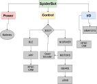
![]()
Electronic System Design
By Electronic and Control Engineer Shaun Pasoz
Last semester’s SpiderBot ran into several areas of difficulty; the worst of which was dynamic walking. They used servo motors to control the actions of the robot. While servos are excellent devices as they provide feedback from the motor, their pitfall is they cannot sustain a large amount of weight. Therefore, this semester we have been tasked to implement a SpiderBot featuring DC motors.
Since the 3DoT board can only supply a current of 450mA, it is highly probably that we will need to implement an external power supply. In order to get the greatest motor efficiency, the first step is to decide on what configuration we would like to choose for our power supply. The following table shows a simple trade-off study between different batteries.
| Battery: | Weight: | Rated Voltage: | Capacity: | Cost: | Size: | Discharge: |
| Ultrafire 18350 1200mAh 3.7V Unprotected Lithium Ion (Li-ion) Button Top Battery | 20.9g | 3.7V | 1200mAh | 4.95 | 35×18.5 mm | N/A |
| 6V Tenergy 1600mAh NiMH Side by Side Battery Pack with Hitec Connector | 130g | 6V | 1600mAh | 10.99 | 84x17x30. mm | 10C (10.6A Calculated) |
| Efest 18650 3000mAh Flat Top Battery – Purple Series | 46g | 3.7V | 3000mAh | 8 | 18.23×65.02mm | 20A Continuous |
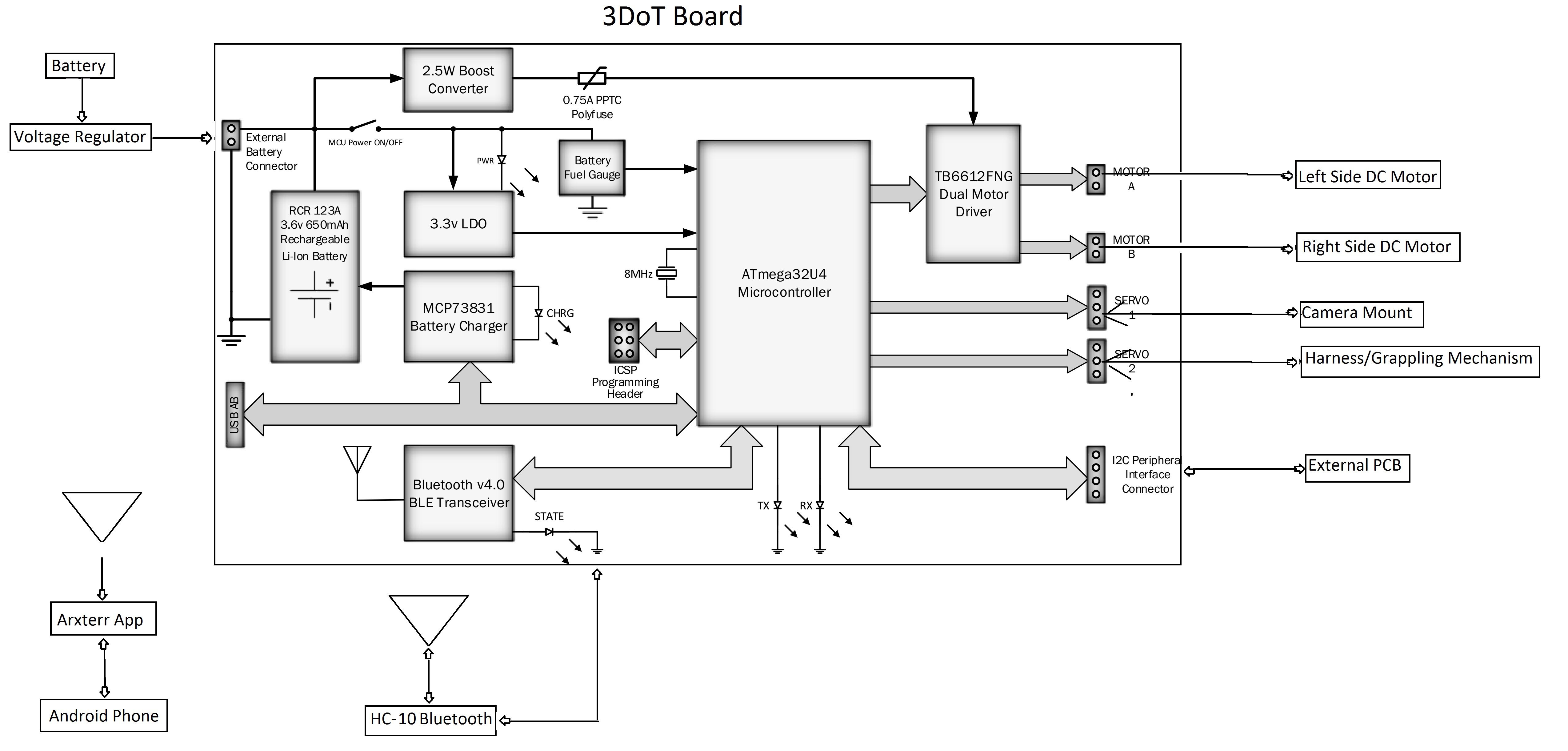
System Block Diagram
By Mission, System, and Test Engineer Jeff Fuentes
The system block diagram displays how Spiderbot’s proposed inputs and outputs will function. The 3DoT board can supply its own power, but it is not enough for all the peripherals we will be using. Communication and telemetry will be handled by the 3DoT board consisting of the HM-10 Bluetooth LE module, an android phone, and the Arxterra app. The motor outputs on the 3DOT board will drive two DC motors which will supply mechanical engery to a set of four legs each. As dictated by the mission objective, Spiderbot will make use of a camera and harness/grappling mechanism via servo control. An external PCB will allow for further function if the 3DoT board cannot fully deliver.
3DoT Board Schematic
- http://web.csulb.edu/~hill/ee400d/Technical%20Training%20Series/3DoT/3DoT%20Datasheets/Block%20Diagram.pdf
- https://www.arxterra.com/3dot/
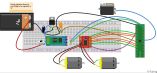
Fritzing Diagram
Mechanical Design
By Maunfacturing Engineer Daniel Matias

Our spiderbot will be based off the terrabot model and be built using 3D printed ABS plastic parts for our first rapid prototype. I will design the parts myself using solid works to have them 3D printer ready.
The body of the spiderbot will be large enough to house the 3Dot Board and two motors with gears to run the Theo Jansen walking mechanism for the legs.

Design and Unique Task Description
By Mission, System, and Test Engineer Jeff Fuentes
Nicholas Jacobs
- Research prospective sources for material/services
Jefferson Fuentes (Missions, Systems, and Test Engineer)
- Design potential schematic to begin fritzing diagrams
- Work in conjunction with E&C (P, Shaun) to analyze power requirements needed for motors and peripherals
- Begin decoding and designing Arxterra app.
- Conduct trade off studies concerning DC Motors alongside E&C
- Conduct trade off studies concerning our harness/grappling mechanism
Shaun Pasoz (Electronics & Control Engineer)
- Consult fellow Electronics and Control engineers to discuss parameters to implement a game to demonstrate 3DoT Board capabilities.
- Examine trade-off studies for various batteries and motors.
- Work on simulations for motor control through the Arduino Uno board to help limit decisions between motor choices.
- After choosing motor, stress tests on motor gear systems need to be conducted to detail the max current draw based on the weight of the robot.
- After deciding on proper motors, batteries, and control systems, conduct tests to analyze how long the battery can run on a single charge.
- Create a Fritzing diagram using parts from interface matrix
- After finalizing electronic layout, create a PCB layout using CAD software.
- Consult Systems Engineer to develop software subroutines to make the SpiderBot perform its tasks.
Daniel Matias (Manufacturing Engineer)
- Conduct trade-off study to determine which material will best suit our needs
- Begin designing and implementing 3D models to be potentially built
- Begin preliminary EagleCAD files to gain an idea of layout
Resources:
http://arxterra.com/preliminary-design-document-4/#h.pit64qv19iz