Table of Contents
Suggested Reading
NASA System Engineering Handbook Section 6.1.2.1 “Work Breakdown Structure” and Section 4.3.2.1
“Product Breakdown Structure.” Also, review page 312 Figure G-1 where a PBS Example is provided.
The Robot Company WBS
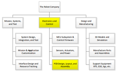
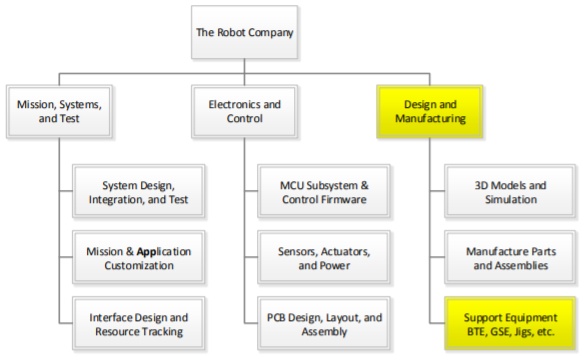
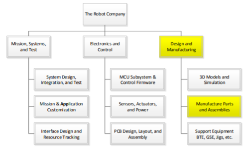
This document describes how The Robot Company is structured technically known as the Company Work Breakdown Structure (WBS). From your perspective, the WBS describes your responsibilities within the company. In that spirit, I have worded the sections in the form of Job Descriptions and named the document accordingly.
|
As the names imply the WBS provides a breakdown of the work that needs to be accomplished to build the product, while the PBS provides a breakdown of the product ITSELF. |
During the first phase of the project, your manager will create a project WBS, based on this one but adapted to your specific robot. Later in the semester, you will hear the term Product Breakdown Structure (PBS). The PBS describes the parts (functional blocks) of the robot. The PBS is the responsibility of the System Engineer.
To make sense out of the following material, please refer to the Company Matrix Organization Chart presented earlier and the Figure 1 Company Work Breakdown Structure. To learn more, read Section 6.1.2.1 “Work Breakdown Structure” and Section 4.3.2.1 “Product Breakdown Structure” in the NASA System Engineering Handbook. On page 312 Figure G-1 a PBS Example is provided.
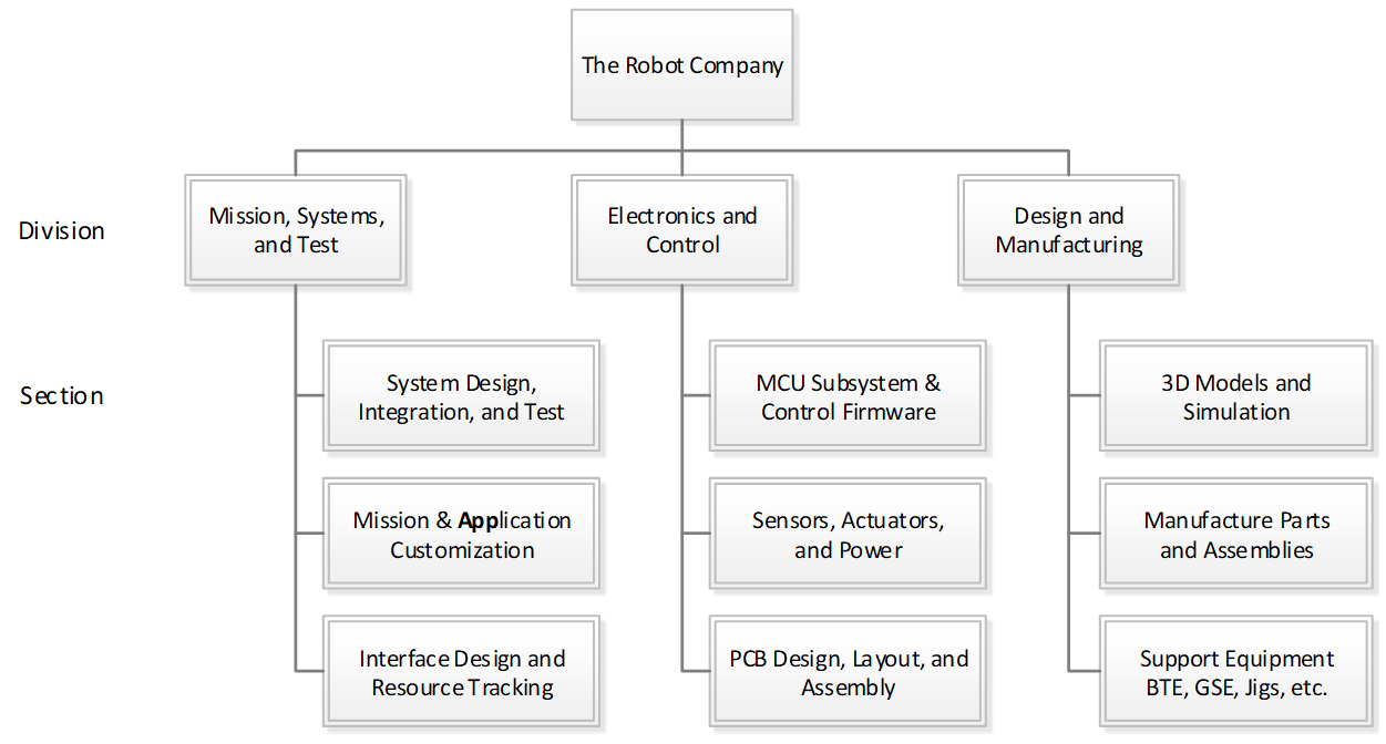
Figure 1 Company Work Breakdown Structure
If the parts of an organization (e.g., teams, departments, or subdivisions) do not closely reflect the essential parts of the product, or if the relationship between organizations do not reflect the relationships between product parts, then the project will be in trouble … Therefore: Make sure the organization is compatible with the product architecture – Conway’s law
The Customer
Task Summary:
- Define mission objectives
- Set cost and schedule goals based on inputs for the project manager and Electrical Engineering Department chair.
- Validate project design
The Robot Company President
The president is responsible for the management of all Robot Company projects. Coordinate working from the customer’s mission objectives to develop the program requirements for each project. Will allocate limited financial resource between projects.
[expand title=”Task Summary“]
- Work with the customer(s) to define Program/Project Level 1 Requirements
- Train Project and Division managers
- Ensure company meets cost and schedule goals set by the customer(s)
- Support project and division managers
- Look for synergy between projects
- Assess performance of Project and Division Managers
As the president, you will be responsible for the management of all Robot Company projects.
Working from the customer’s mission objectives, you will develop the program requirements for each project.
You will also work with the customer to allocate limited financial resources between the projects. You will be scheduling all project deliverables including the Project Plan, Preliminary and Critical Reviews and Associated Documents.
You will be working closely with our project managers helping them manage cost, schedule, and performance, including…
- Assisting the project managers in their preparation for reviews and written documents.
- Assisting the division managers in the development and execution of their training plans.
Working with the project and division managers, you will also identify areas of synergy between the projects allowing better utilization of limited engineering resources.
Keep close communication with joint projects (cross course integrated projects) to ensure each division manager, project manager and engineer are in agreement and compliance with the Interface Control Document (generated by Mission, Systems and Test Division). Requires close communication and collaboration with the presidential counterpart in second-course section.
Along with the customer and management staff, you will, on a periodic basis, assess each project and division manager’s performance.
Qualifications
An educational background in business and/or management experience, or a desire to learn is a plus.
[/expand]
Quality Control Engineer
The QA Engineer working with the project and division managers, will insure that project plans, documentation, presentations, and blog posts are consistent with those generated by working engineers and reflects well on the CSULB COE and EE department.
[expand title=”Task Summary“]
Insure quality is built into each project. For example, is the robot easily assembled and disassembled. Does the robot not undergo “Rapid Unscheduled Dissembly” RUD.
Cabling
Although, typically not the responsibility of the Quality Assurance Engineer, you will take the “interface definition” to the next level down by defining the “cable tree” for each project. To accomplish this task you will working with the system, electronics and control, and manufacturing subsystem engineers, from each project to specify analog/digital signal and power connectors, cables, and how they will be routed (the tree). Specifically, insure NO wires are exposed and all cabling includes connectors and routing is designed-in.
Factor in interference with other design elements and how to keep the overall cleanliness of the design. In other words, when assembled, the product should not look like a rat’s nest.
Blog Posts
Manage the class website. The QA engineer is the gate keeper insuring that all blog posts meet all requirements before posting.
- Blog is posted to the correct location on the website.
- Includes correctly formatted square teaser photo and “Introductory” paragraph with a “Read more à” link.
- Identifies project member(s) who created the post.
- All images are formatted for the web!
- Does not plagiarize material.
- All code examples use courier font and single spaced.
Make an effort to attend project and division meetings.
[/expand]
Project Manager
Define projects level 1 requirements, hold project meetings, manage and keep tasks on schedule. Working with your team to make your robot a success. Success will be defined by meeting cost, schedule, and performance requirements.
[expand title=”Task Summary“]
- Build Project Team
- Define Project WBS and PBS
- Define Program/Project Level 1 Requirements
- Track and manage project budget and schedule
- Lead Weekly Project Meetings
- Report to the Company President
- Communicate with Division Managers
- Edit Project Documentation
- Project Video
- Assesses the contribution of Project Members
The successful candidate(s) will manage one of our Robot Projects. You will initially be negotiating with the division managers to build your project team.
Next, you work with the system engineer to define your project unique WBS. You will assist the System Engineer in developing the PBS.
Working with the customer, you will write the Level 1 Program requirements. Working with the System engineer, you will next write the Level 1 Project requirements. These requirements will be codified in the Project Plan.
You will then be working with your team to make your robot a success. Success will be defined by meeting cost, schedule, and performance requirements.
Qualifications
An educational background in business and/or management experience, or a desire to learn is a plus.
Assessment
During the semester, on a periodic basis, the project manager will assess the performance of each engineer within their project. At the same time, the president and management staff may also grade the members of your team. The instructor shall take these recommendations into consideration when assigning grades to engineers within your project.
Meetings
The Project Manager leads a weekly project meeting. As part of the meeting, the project manager should assign someone to take the meeting minutes. The project manager is responsible for editing these minutes and uploading them to BeachBoard in a timely manner. Keep president informed of weekly project meeting date, time and location for occasional attendance.
The Project Manager is responsible for scheduling a weekly meeting with the President. This meeting may be as short as 15 minutes. The meeting may occur during the lab time. The project manager is responsible for taking the minutes during the meeting. An edited version of the minutes are to be provided to the president and the instructor prior to the next meeting.
Project Video
The project video is the last deliverable provided by the project. Its objective is to act as a recruiting tool for high school students considering electrical engineering at CSULB. It should also showcase our work to the COE and its corporate sponsors. The video must also present the engineering process as applied to the design and construction of your project. Points earned are “bonus.” The project manager may want to assign video production to someone with video editing experience or a team member who could benefit from the “bonus” points assigned.
Final Documentation
Although Physical copies of reports are still alive and well in industry, to keep the instructor’s office as uncluttered as possible, we will be storing all our documents on the cloud.
The project manager is responsible for compiling, organizing, and editing the key documents and reports (selected blog posts) generated over the semester by the project into a Final Documentation Blog Post. This will ensure your documentation and videos are not lost over time.
[/expand]
Division Manager
Present training material to the division members in the form of hands-on lectures and assess learning with assignments and/or exams. Manage cross-links between projects and find and manage resources within your division.
[expand title=”Task Summary“]
- Manages Division Engineering Resources
- Responsible for Training
- Leads Weekly Division Meetings
- Reports to the Company President
- Communicate with Project Managers
- Assesses the contribution of Division Members
The first task of the Division manager will be to assign engineers within his or her division to each project.
Division managers, at their discretion, may also assign an engineer to be a section manager. If not assigned, the Division manager will act as the section manager.
Over the course of the project, you may dynamically reallocate your engineering resources due to:
- Changing needs of a Project which may require additional help or temporary reassignment of an engineer with a unique skill set.
- Successful completion of a task
- Poor performance in support of a project
Present training material to the division members in the form of hands-on lectures and assess learning with assignments and/or exams.
During the semester, the division manager shall provide reading and/or homework assignment to help division members learn the material. On a periodic basis, no less than every 2 weeks, the division manager will assess the performance of each engineer within their division by giving a quiz. The quiz shall be over a set time limit, where the division members may, at the managers discretion be allowed a sheet of notes. It is important to distinguish between helping division members learn the material and assessing their mastery of the material.
Learning assessment grades shall form a part, but not the totality of this grade. At the same time, the president and management staff may also grade the members of your division members. The instructor shall take these recommendations into consideration when assigning grades to engineers within your division.
Meetings
The Division Manager leads a weekly division meeting. As part of the meeting, the division manager should assign someone to take the meeting minutes. The division manager is responsible for editing these minutes and uploading them to BeachBoard in a timely manner. Keep president informed of weekly division meeting date, time and location for occasional attendance.
The Division Manager is responsible for scheduling a weekly meeting with the President. This meeting may be as short as 15 minutes. The meeting may occur during the lab time. The division manager is responsible for taking the minutes during the meeting. An edited version of the minutes are to be provided to the President and the instructor prior to the next meeting.
[/expand]
Mission, Systems, and Test Division
Divison Manager
Manage the Mission, Systems and Test Division and associated sections. See the Division Manager section for a general job description. Responsibilities of the engineers within this division are described in the following subsections.

[expand title=”System Design, Integration and Test” tag=”h4″]
Resources:
- NASA Systems Engineering Handbook
- GSFC Rules for the Design, Development, Verification, and Operation of Flight Systems
Task Summary:
- Define WBS and PBS
- Define Level 2 System/Subsystem Requirements
- Interface Control Document (ICD) if applicable to your project
- System Electronic Interface Design
- System Software Interface Definition
- Cable Tree
- Grounding Strategy
- Manage system resources
- Generate verification and validation test plan
- Build summary verification and validation checklist
- Look for the Intangibles
System Design
First task will be to work with each project manager to define unique WBS for each project. Working from the WBS and subsystem engineers, define the PBS.
Requirements
Working with the project manager, help develop level 1 program and project requirements. The project manager is ultimately responsible for generating Level 1 program requirements. Working from the level 1 requirements, and with the subsystem engineers, write the level 2 system and subsystem design requirements. Subsystem engineers are ultimately responsible for the generation of subsystem requirements.
Integration and Test (Requirement Verification and Product Validation)
Working with customer and each system engineer, develop a product requirement verification and validation test plan. This plan includes the tests to be conducted to verify requirements and validate the design. Avoid qualitative definitions like “visual inspection.”
Part of the plan includes a summary verification/validation checklist. The checklist breaks down requirements by numbering them, stating the requirement, providing rationale for the requirement, and then breaking down the level of success of the requirement into a percentage.
Look for the Intangibles
Finally, a good system engineer looks at the project as a “complex system” and how it might fail or not meet customer expectations during the mission (Project Validation). This is a critical part of ConOps (Conceptual Operations) whose purpose is to discover holes in the definition of the design (the intangibles) before the start of the mission.
1.1.4.1 Case Studies
Here are some examples of ConOp failures.
A vacuum system for use in a lab might be defined in millimeters of mercury (mmHg), but once the machine is built the noise generated (decibels) makes it useless for use in a lab environment.
The stability of a walking robot might be defined by the impact of a rod of radius r (cm) located at a given distance d (cm) at height h (cm) from the robot, with mass m (kg) moving a velocity v (cm/sec) for a period of t seconds. The robot is designed to pass this test, only to fall over if a lesser force is applied. So the robot passes the defined test but fails the spirit of the requirements.
The field-of-view (FOV) of an articulating camera mirror system mounted on a rover is not defined. On the day of the final half of the camera’s FOV is the floor.
A pan and tilt subsystem is designed and tested to meet FOV requirements only to discover when mounted on the spider robot that the pan and tilt subsystem impacts the leg servos when panned down.
A large capacitor on a PCB was designed to close to an IR sensor connector preventing the sensor from being plugged into the robot.
[/expand]
[expand title=”Mission and Application Customization” tag=”h4″]
Programming is not a traditional role for a system engineer, but moved to this level to focus additional attention onto this too often forgotten area.
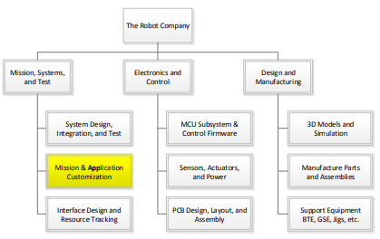
Task Summary:
- Configure mobile device App
Configure the application software required to remotely control the robot. Control may be done from a PC and/or cell phone (Android or iPhone) application.
If no off-the-shelf application exists to remotely control your robot, it will be necessary to generate this code. If the project falls within this category, it will be useful to have a background in programming in one or more high-level scripting languages like Processing, HTML 5, Java, or MATLAB.
[/expand]
[expand title=”Interface Design and Resource Tracking” tag=”h4″]
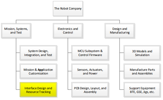
System Electronic Interface Design
Working with the electronics and control subsystem engineer(s) within each project, document the System Interface Design, which includes the System Block Diagram and Interface Design Matrix.
Power Distribution Strategy
The system engineer, working with the electronics and control and manufacturing engineer, is responsible for defining the power distribution strategy (star and/or multipoint) at the PCB and System level.
Interface Control Document (ICD)
In some cases, projects will be interfacing with another project. Fall ’16 examples include the Prosthetic Arm (Wednesday class) to the Prosthetic Hand (Thursday class) and the Pathfinder Solar Panels (Wednesday class) to the Pathfinder Chassis (Thursday class). For these projects, the systems engineers will work together to write an ICD documenting the electrical connectors and cabling, power, mechanical, and other interfaces associated with the integration of the two projects. Work closely with MST counterpart in other class section, project managers for each project, and president from each class to ensure ICD is being followed. Encourage joint project meetings throughout the life of the project to help maintain communication between groups.
System Resources
Manage all applicable system resources. Resource management typically includes, but is not limited to, mass and power. For example, on a spacecraft, Field-of-View is a resource. When reporting to management, please include margins and contingencies. Margins are applied based on uncertainty in a given line item. Contingency is applied across the resource and is a function of the system resource budget minus the expected value and total margin. Resource reports should be updated on a periodic basis, typically defined by the president. As a rule of thumb, resource reports should be updated every other week and included in the meeting minutes.
[/expand]
Electronics and Control Division
Division Manager
Manage the Electronics and Control Division and associated sections. See the Division Manager section for a general job description. Responsibilities of the engineers within this division are described in the following subsections.

[expand title=”MCU Subsystem and Control Firmware” tag=”h4″]
Task Summary:
- Software Definition
- MCU Communication Firmware
- MCU Subsystem Command and Telemetry Firmware
- MCU Subsystem Control Firmware
Write software subroutines and functions as defined by the software system block diagram. For robots implementing complex motion algorithms, this includes creating a data structure array in SRAM or Flash program memory to define the motion.
Specifically, responsibility of the electronics and control engineer will be to write the firmware required to translate commands into control signals to the actuators, read sensors and translate into data bytes, and implementation of any control algorithms. Communication with the Bluetooth module and decoding of command packets is the responsibility of the systems engineer. The systems engineer is also responsible for collecting and packetizing the data bytes and subsequently sending them to the Bluetooth module.
Qualifications
A background with embedded systems, the Arduino IDE, and the C++ programming language or a desire to learn is a plus.
Software Definition
Develop a software system block diagram. The description of the block diagram should define the function of each module and how they will communicate. For example, number of arguments and their data type, plus return value and data type.
MCU Communication Firmware
The Micro-Controller Unit (MCU) Communication firmware[1] receives and decodes commands and sends telemetry to the Bluetooth device on the robot. The software’s responsibility stops once a command is decoded. For most projects, the E&C engineer will adapt existing C++ programs written within the Arduino IDE for this purpose.
If the project does not fall within the category of having an off-the-shelf application to decode commands and send telemetry, then it would be necessary to have a strong background in programming in C++.
MCU Subsystem Command and Telemetry Firmware
To control actuators and read sensors, software will interface with the peripheral subsystems of the microcontroller including: Timers (e.g., Fast PWM mode), ADC, TWI, SPI, EEPROM, and USART. The Robot Company has developed extensive material on working with the ATmega328P and on how to program its subsystem modules in C++.
MCU Subsystem Control Firmware
The successful candidate(s) will be responsible for the onboard software associated with the stability and tracking control of the robot. Most robots will implement one or more PID control algorithms.
Control input will typically be from an IMU.
For this sub-task a background in embedded systems, C++ programming, and control theory (EE470 and EE471) or a desire to learn is a plus.
[1] Software located in Flash program memory.
[/expand]
[expand title=”Sensors, Actuators, and Power” tag=”h4″]
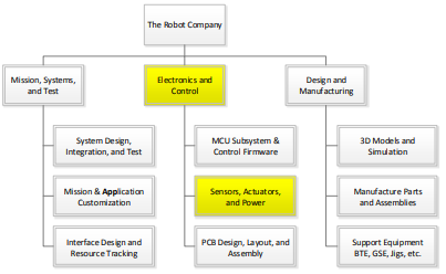
Task Summary:
- Define sensor suite
- Define actuators including electromechanical devices and subsystems
- Define communications subsystem
- Define power subsystem
Electronics and control engineer is responsible for selecting and implementing the sensors, actuators and power subsystem to be carried on the robot.
Sensors
Sensors can be as simple as a resistor divider to measure battery voltage and as complex as a SLAM mobile device. In the following paragraphs, sensors typically found on a robot will be discussed.
For measuring target distance, a number of sensors need to be considered including IR, Lidar, Ultrasonic, or camera. Trade-off studies to select a sensor should consider how measurement errors are introduced by the environment (e.g. lighting, reflections, and target surface properties). Also consider the peripheral subsystem required by each sensor type. These may include the ADC or a serial peripheral interface like the I2C, SPI, 1-wire, and USART. A wealth of information can be found on the Internet and here.
For measuring the distance traveled by a robot, consider the addition of a shaft encoder. The trade-off study should investigate traditional (opto and hall effect sensors) and sensorless (commentator and back emf) solutions for measuring the rpms of a DC motor.
For measuring angular rotation and/or velocity to control the stability and tracking of the robot, consider gyro, accelerometer, and magnetometer or some combination of all three incorporated into an Inertial Measurement Unit (IMU). If an IMU is adopted, sensor data may be smoothed using a Complementary or Kalman Filter algorithm. Some commercially available modules incorporate both the IMU and filter.
For measuring battery state, purchase a fuel gauge or simply use a resistor voltage divider.
Actuators
An actuator is defined as any output device. This includes optical devices like LEDs and Lasers. It also includes electromechanical devices like solenoids, servos, and motors.
Electromechanical Devices
Specification of electromechanical devices, like servos and motors, should be based on quantitative system/subsystem design requirements. From these “specifications”, a trade-off study is typically conducted. The trade-off study usually takes the form of a table where the robot’s desired specification for the electrometrical part is in the first column. The subsequent columns contain the specifications gleaned from the datasheet of candidate commercial off- the-shelf (COTS) parts. The selected parts are then purchased and tested against the original robot specification. These tests should consider static and dynamic loads plus life-cycle testing under worst case load conditions.
Case Study
Up to the Spring 2016 Semester, no SpiderBot has ever completed its mission due to insufficient static and dynamic modeling (back of the envelope and at 3D modeling) at the system level, mass resource management, and life-cycle testing under load conditions.
Electromechanical Subsystems
Electromechanical devices are often combined into subsystems. Robots’ subsystems may include the powertrain and a pan and tilt platform.
Powertrain
The powertrain includes: DC motors and/or servos, transmission (the “gearbox”), and drive electronics (H-Bridge, Shift Register, Power Transistors …). For this subsystem, an educational background in motors and motor control (EE451) or a desire to learn is a plus.
Pan and Tilt Platform
For the robots, the pan and tilt platform carry the mobile device (Android or iPhone). Actuators may include a stepper motor or servo for panning and almost always a servo for tilting.
Communications
For most robots, a Bluetooth module will be incorporated into the design.
Power
The power subsystem may include batteries, charging circuits, DC-to-DC converters, and voltage regulators (linear and LDO). For some robots, consider the addition of solar panels.
DC-to-DC converters may step-down (buck) the input voltage, step-up (boost) the input voltage, and in some cases both. A step-down (buck) converter is also referred to as a UBEC which stands for “Universal Battery Eliminator Circuit”.
Research battery solutions based on quantitative subsystem requirements, resource reports (mass and power), and project requirements (mission duration, safety, etc.). Battery technologies include, but are not limited to, NiCD, Nimh , LiFePO4, and Li-Ion/Polymer. Based on requirements, other power sources may be investigated such as solar.
[/expand]
[expand title=”PCB Design” tag=”h4″]
Task Summary:
- Working from interface matrix, create a Fritzing diagram
- From fritzing diagram, build breadboard
- Write C++ test software programs both to control the actuators and collect data from the sensors
- Test breadboard
- Using Eagle CAD (schematic capture), create electrical schematic
- Test finished PCB
Working from the PBS, System Block Diagram, and Interface Matrix, provided by the system engineer, the electronics and control engineer designs the robot’s Printed Circuit Board (PCB). Working from the provided material, the electronics and control engineer also creates a Fritzing diagram, makes and tests the breadboard, and captures the design, in the form of a schematic, using CAD software (typically Eagle CAD). The manufacturing division is then responsible for laying out the PCB and providing to the Electronics engineer a completely assembled PCB. The electronics and control engineer is then responsible for testing the completed PCB.
PCB Layout and Assembly
Task Summary:
- Layout a PCB with Surface Mount Technology (SMT) discrete components and ICs
- Generate Gerber file and order a SMT solder paste stencil.
- Reflow and hand solder PCB
Working from a schematic, provided by the electronics and control engineer, the power distribution strategy, provided by the system engineer, and the physical constraints of the robot, the manufacturing engineer will design the printed circuit board (PCB), perform ERC and DRC checks, generate the CAM file and upload to a PCB house for fabrication. This process is typically carried out using Eagle CAD.
In addition to the PCB, it will be necessary to purchase the SMT solder paste stencil used for applying paste to the PCB as part of the reflow soldering process. The design of the stencil is generated in Eagle CAD and output as a Gerber file.
Once the PCB and stencil are received, the manufacturing engineer is responsible for reflow soldering of the SMT discrete components and ICs onto the board, as well as hand soldering through-hole discrete components. The board is then given to the electronics and control engineer for testing.
[/expand]
Design and Manufacturing Division
Division Manager
Manage the Design and Manufacturing Section. See the Division Manager section for a general job description. Responsibilities of the engineers within this division are described in the following subsections.

[expand title=”3D Models and Simulation” tag=”h4″]
Task Summary:
- Use CAD/CAE software to design the robot
- Use CAD/CAE software to design the mechanical parts
- Run static and dynamic simulations
The successful candidate(s) will use a solid modeling computer-aided design (CAD) and computer-aided engineering (CAE) software program, typically SolidWorks, to design the mechanical parts, sub-assemblies, and even the robot itself. The overall design must take into consideration all parts manufactured and purchased. The most commonly forgotten parts are the connectors and cabling.
Working with the systems engineer, determine the acceptability of the design by running simulations. These may be in the form of system level animations (e.g., for bipedal robots the walking motion while tracking center of mass), system level load and shear analysis (e.g., for spiders a stress analysis across the body-servo-leg interfaces), and others as seen appropriate.
Qualifications
Work experience with a 3D modeling program or a desire to learn is a plus. Preferred modeling program is Solidworks; however, a working knowledge of Blender, AutoCAD, SketchUp or any other CAD/CAE program will be taken into consideration.
[/expand]
[expand title=”Support Equipment” tag=”h4″]
During the design and development phase, E&C engineers will need to test electronics. The manufacturing engineer shall provide support in the design and fabrication of any Bench Test Equipment (BTE), Ground Support Equipment (GSE), and Test Jigs on an as needed basis.
[/expand]
[expand title=”Manufacture Parts and Assemblies” tag=”h4″]
Task Summary:
- Manufacture mechanical parts
- Specify and order off-the-shelf parts
Parts may be fabricated using additive (3D printers), subtractive (CNC, laser cutter, lathe …), or other (vac-u-form, molds …) manufacturing techniques. It is important to work with the manufacturing Division Manager to find the manufacturing technology required for the project.
Off-the-Shelf Parts
Specify and order miscellaneous parts including:
- Fasteners – nuts, bolts, screws, washers…
- Adhesives and Sealants – tape, velcro, zip-ties, O-rings, weather stripping, silicone tube…
- Powertrain Components – belts, gears, bearings…
- Hardware – grommets, brackets…
The customer has a large number of fasteners, powertrain components, and other hardware. Otherwise, purchase such parts from Home Depot and McMaster-Carr among others.
Case Study
The manufacturing engineer of a robot has a friend with a 3D printer. He asks his friend if she will print the parts for their robot. The friend agrees, assuming that the STL files will be provided within a few weeks.
Case 1: Near the end of the semester, the friend receives the STL files and realizes that they simply do not have time to print the parts. What should the manufacturing engineer have done to avoid this problem?
Case 2: The STL files are provided within a few weeks. However, the friend says her 3D printer is broken and she simply does not have time to fix it. Because the engineer now has time to recover from this disaster, instead of running around asking everyone if they have a 3D printer or purchasing time on a 3D printer, he contacts the Division Manager for help. The Division Manager bring up the problem at the next division meeting and another 3D printer is located. This is the strength of the matrix organization!
[/expand]
Test Your Knowledge
Design
- Who is responsible for designing the cabling layout?
- You want to build a pan and tilt platform. Who is responsible for the specification of the servos?
- You want to build a pan and tilt platform. Who is responsible for the design of the brackets to hold the servos?
- Who is responsible for calculating the torque specification for the servo?
- Who is responsible for simulating the pan and tilt platform to insure it will meet FOV requirements.
- Provide one or more examples of a ConOps failure?
Testing
- Who is responsible for designing robot verification tests?
- Which division(s) are involved in testing the robot?
Printed Circuit Board
- Which division(s) are involved in the design, fabrication, and testing of the PCB?
- What part does the System Design engineer play in the design of the PCB?
- Who designs the circuit schematic?
- Who board layout of the Printed Circuit Board (PCB)
- Who is responsible for assembling the PCB?
- Who is responsible for testing the PCB?
Software
- Which division(s) are in involved in software development?
- Your project has decided to develop an iPhone powered spider robot. Who is responsible for customize the Arxterra application to control the spider robot?
- Who is responsible for implementing commands?
- Who is responsible for sending telemetry data packets to the Bluetooth module?
- Who is responsible for writing the firmware to translate sensor inputs into data bytes?
- In which computer can you find the MCU communication firmware?
Other
- Who is responsible for drafting the product breakdown structure (PBS)?
- Your project has decided to use a CNC machine to fabricate a part for your robot. Who should you look to for help?
- Who is ultimately responsible for assigning your grade?
- If you were going to fly a payload on the Space Shuttle, NASA Johnson Spaceflight Center (JSC) reassured you that all surface in the payload bay would be visually clean. Is this a quantitative requirement?
- How often should system resources be updated?