Custom Commands and Telemetry
Table of Contents
Custom Commands
When opening the ArxRobot application, the first thing to notice is the Direction-Pad (D-Pad), or the arrow keys, on the screen. The ArxRobot application will be used to completely control the 3DoT robot manually. What about the commands specific to the robot being programmed? How can an LED be turned on manually? How can the stance of the robot be set to appear aggressive or defensive? In this section, it will discuss how to create custom commands and type of custom commands available on the ArxRobot. For more information on Arxterra Custom Commands and Telemetry, check out the Arxterra YouTube Channel. The video below covers creating custom commands and telemetry in great depth.
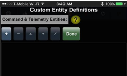
This section assumes that the basic set up with the ArxRobot application has been reviewed. If not, start with the section “03 – Getting Started with Arxterra”. Start with opening up the ArxRobot on a mobile device. Enable “Developer Mode”, which allows the user to edit the interface of the control panel. Open the developer options, located on the left of the “Developer Mode” represented as a gear. Click on the option “Custom Command & Telemetry Configuration”, which will direct the user to a screen titled “Custom Entity Definitions” as shown in Figure 10.1. On this screen, it is possible to create all user custom commands.
Figure 10.1: Custom Entity Definitions window
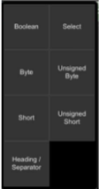
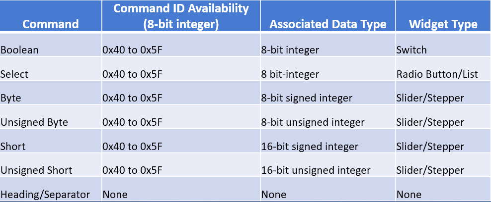
Proceed with clicking on the button labeled “+”. This symbol indicates adding a new custom command. For further information on the rest of the buttons, hold on to the yellow circle with the question mark. These yellow circles are present in multiple areas of the ArxRobot application and are known as “Tips”. “Tips” are descriptions to help the user on certain items in this app. By clicking on the “+” button, a window of types of custom commands will pop up. There are seven types of custom commands Arxterra offers in which this section will go over: Boolean, Select, Byte, Unsigned Byte, Short, Unsigned Short, and Heading/Separator.
Figure 10.2: Custom command types
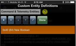
Figure 10.3: New Boolean Custom Command Added
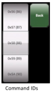
By selecting of the command types will add them to the window space. Selecting an added command in the window space will allow you to: delete, move up or down, or edit the command. Notice when you add your first custom command, your new command begins with a command ID of 0x40. This value is used by the microcontroller on your 3DoT board to identify what instruction it is receiving. Keep in mind, the Command ID range available for the user is from 0x40 to 0x5F. You can edit the command ID of any command to within mentioned range by pressing on the edit button (pencil icon on the button row) while having your intended command highlighted on the command window.
Figure 10.1: Custom Entity Definitions window
In the following sections, we will look at each of these seven (7) Arxterra custom command data types.
| Arxterra Data Type | Command Widget | Telemetry Widget |
| ● Boolean | Switch | |
| ● Select | Radio Button or Drop Down Menu | |
| ● Byte and Unsigned Byte | Slider or Stepper | Text Box |
| ● Short and Unsigned Short | Slider or Stepper | |
| ● Heading/Separator |
Boolean Command
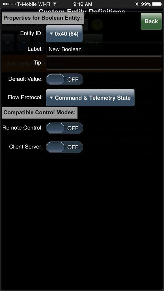
A Boolean Command is used when the custom command you are creating has only one input and only two outcomes: On or Off. This command is implemented as a switch. Since there is only one output, there will be one byte following the command ID when this is sent to the microcontroller. For a command ID of 0x40, and the switch in the OFF (0x00) and ON (0x01) state, these are the two corresponding command bytes: 40 00 and 40 01. After pressing the “Add” button (Figure 10.3) a “Property for Boolean Entity” window open.
Properties for Boolean
- Entity ID: Gives the command an ID (in HEX)
- Label: Gives the command a name
- Tip: Hover-over description of the command on the control panel (optional).
- Default Value: Default value for the command when the control panel begins.
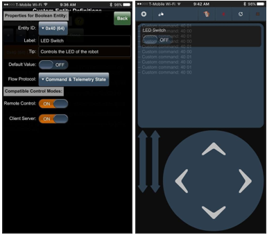
- Flow Protocol: The “Flow Protocol” property for our example command is set equal to “Command and Telemetry.” This selection allows both the user and microcontroller to toggle the Boolean switch ON or OFF. The alternative is to set this property to “Telemetry.” The Telemetry state allows only the microcontroller to update the state of the switch, and the user to view the state of the switch on the control panel.
By using the “Telemetry” flow protocol, the switch will appear under the telemetry panel (left image above) on the control panel, while using the “Command and Telemetry” state will have the switch appear under Custom Controls (right image above).
- Compatible Control Modes: Choose where the command will be available for use on the Phone app, Control Panel, or both.
Figure 10.4: Boolean entity options
Figure 10.7: Command set to appear on both the control panel (Figure 10.6) and Phone App.
Select Command
A Select Command is used when the custom command has multiple outputs with varying output values. Select command “Widgets” may be shown as “Radio buttons” or a “Drop-down list.” In a Select Command, you can increase the number of options (radio button or list item) available to click on, along with the argument to be sent when the option is selected. Keep in mind, however, the Select command still only sends one byte argument to the custom 3DoT command handler.
Properties for Select
Properties common to other Arxterra custom command data types , including Boolean are shown in gray. The reader is referred to the previous section for a discussion of these common properties.
- Entity ID: Gives the command an ID (in HEX)
- Label: Gives the command a name
- Tip: Hover-over description of the command on the control panel (optional).
- Default Value: Default value for the command when the control panel begins.
- Widget: Choose between the two Widget styles: Radio buttons or Select list. The type of widget you choose will not affect the command packet being sent to the MCU, but the look on the control panel. Select the most appropriate style for your robot design.
- Compatible Control Modes: Choose where the command will be available for use on the Phone app, Control Panel, or both.
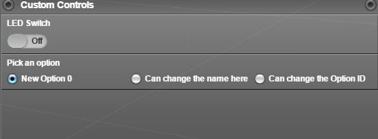
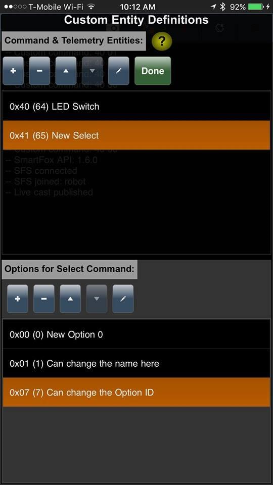
For the example shown in Figure 10.8, three radio buttons are to be displayed with labels “New Option 0”, “Can change the name here”, and “Can change the Option ID” (Ed. Note: I did write this example). When selected these three buttons would be sent as 41 00, 41 01, and 41 07.
Figure 10.8 Radio Button Example with Command and Telemetry flow protocols
Figure 10.8: Select Custom Command
In this next example, we look at a drop-down widget as it would appear with a “Telemetry” flow protocol (left image above) on the control panel and a “Command and Telemetry” protocol (right image).
Figure 10.9 Drop down list Example with Telemetry (left) and Command and Telemetry (right) flow protocols
Byte and Unsigned Byte Command and Telemetry
The Byte and Unsigned Byte will be covered together as both command and telemetry types are very similar to one another with only one major difference between them. The Byte and Unsigned Byte command offers the ability to select or display any integer value between specified ranges. The Byte offers ranges from -128 to 127 while the Unsigned Byte offers ranges from 0 to 255. The main difference between the two is solely the range. As the developer of your robot, choose the most appropriate values for your design. An example on how to choose is by asking yourself if your custom command will be needing values in the negative range. Again, this type of command will only give one output, but of many options.
Data entry is by a slider or a stepper widget. As a telemetry channel data is displayed as gauge (default) or in a box.
Properties for Byte/Unsigned Byte
Properties common to other Arxterra custom command data types, including Boolean are shown in gray.
- Entity ID: Gives the command an ID (in HEX)
- Label: Gives the command a name
- Tip: Hover-over description of the command on the control panel (optional).
- Flow Protocol: Here we have a new type of Flow Protocol on top of Command and Telemetry states. The purpose of Telemetry stream is to display of the stream of data in a box instead of in a gauge format like the other Telemetry options.
- Default Value: Default value for the command when the control panel begins.
- Widget: Choose between the two Widget styles: Slider or Stepper.
- Maximum and Minimum range: Edit the minimum and maximum range of the custom command. It does not necessarily have to be -127 to 128, but to a value of your choice. An example of this is changing the range to 0 to 180 to indicate the angle for a stepper motor to turn.
- Step: Choose the size of the increments between the Minimum and Maximum range. For example, a step of 10 would be 10, 20, 30…
- Compatible Control Modes: Choose where the command will be available for use on the Phone app, Control Panel, or both.
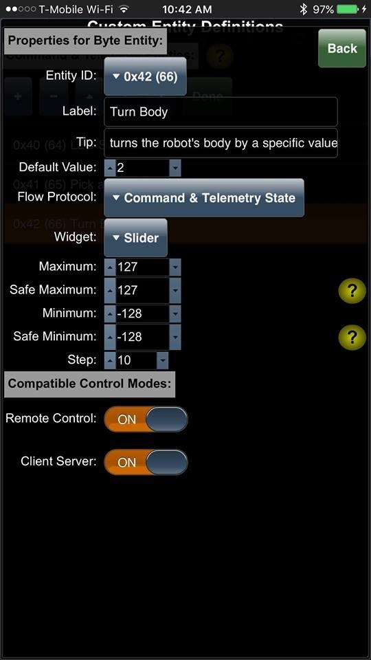
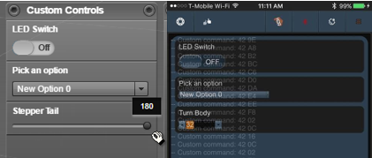
For the example shown in Figure 10.10, a signed Byte in the range -128 to 127 is to be selectable using a slider as illustrated in at bottom left in Figure 10.11. Also shown in Figure 10.11 at right is how the same signed byte would display in the App implemented as a stepper widget. The “Byte” data type is transmitted in 2’s complement form. Which means that -128 to 127 values would sent as byte values FF ⇢ 80. The “Unsigned Byte” data type would be from 0 to 255 sent as byte values 00 ⇢ FF. It is the responsibility of your custom 3DoT command handler to assign the correct data type (int8_t or uint8_t) based on the command ID. For the “Turn Body” example the microcontroller would be sent 42 20.
Figure 10.10: Byte Data Type
Figure 10.11: Byte Data Type implemented as Slider (left) and Stepper (right) widgets
Short and Unsigned Short Command
The short and unsigned short have very similar properties with the byte command types. The difference between the short and unsigned short again are the range of values available. The short command provides a much greater range of values than what the byte offers ranging from -32768 to 32767. A short command would be used over the byte command when the values the custom command you are designing exceeds the values of -127 to 128. Similar to the Unsigned Byte, the Unsigned Short offers no negative values from 0 to 65535. The command sent to the microcontroller is split into two bytes using the Short or Unsigned Short Command. An example of this is 43 FF FF for sending the value of 65535 with the command ID of 43 to the microcontroller.
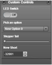
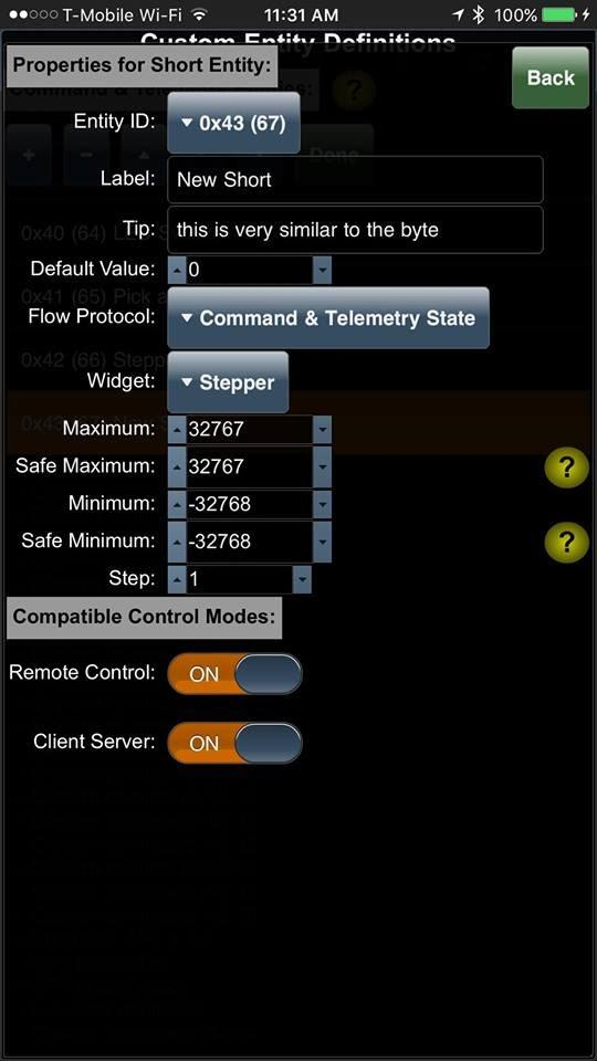
In the example shown in Figure 10.11 a Short Data Type is implemented displayed as a Stepper widget, within the Control Panel. The slider is more convenient for a design that require access to different values throughout the range. Stepper is more useful in an incremental setting, where your command requires to increment at a fixed interval.
Figure 10.13: Short Data Type displayed as a stepper in the control pannel
Figure 10.12: Short Data Type implemented as a Stepper widget
Heading/Separator
The purpose of the heading or separator is to create a more user-friendly custom command interface for the user. The heading acts as a title to show a grouping of certain custom commands. The separator is an empty bar to create a more visual separation between two commands.
The figure below shows the difference between the Heading and a Separator. The Separator is essentially a heading without any text in it.
Figure 10.13: Difference between a Heading and a Setting.
Properties for Heading/Separator
- Label: Give the command a name. Leaving an empty label will cause the heading to function as an unlabeled Separator.
- Tip: Include a hover over tip for the control panel if desired.
The example shown in Figure 10.14 creates a separator named “Types of Slider.” Notice that in order to create a separation between custom commands, you have to change the position of the command in the Custom Entity Definitions window. Also keep in mind, there is no command ID sent to the microcontroller when using a Heading/Separator. This header/separator is only used for cosmetic purposes, hence the reason the heading is given an entity ID beyond the custom command ID limits of 0x40 to 0x5F.
Figure 10.14: Example of a Separator
Design your Control Panel
Now that we have covered all the types of custom commands available, think about what type of custom commands or telemetry will your system be using. Keep in mind that some of the custom commands or telemetry may have already been included by the 3DoT library, so take a look at what is already defined in the Commands and Telemetry table located in the Configure.h file of the Robot3DoTBoard folder. A good example of redundant custom commands is creating a custom turn command. Since the ArxRobot app already provides a D-pad for movement, simply modifying the move command in the 3DoT library is a more logical choice. A good example of this can be found in the Robot3DoTBoard folder under the examples folder as “Robot_3DoT_TeleComm”. Fortunately, the ArxRobot mobile app has made creating custom commands a very user-friendly process as there is minimal coding knowledge required. While you are creating your custom commands, refer to this chart for identifying the appropriate command type.

