Introduction
This guide is meant to assist with putting together the non-assembled version of the IR shield for the 3DoT Starter Kit. As there are many possible configurations for this shield depending on the robot dimensions, we will be focusing on the ideal setup for the Paperbot that is included in the starter kit.
Parts and Recommended Orientations
The following parts should have been included from the IR shield kit.
- One IR Shield PCB
- One 90° eight pin connector
- Four QRE1113 IR Sensors
You will need the following tools to put everything together.
- Soldering iron
- Solder
- Wire clippers
It is also recommended to have the following tools/accessories to make it easier.
- Helping Hands / Clamp to hold the PCB
- Solder wick
- Flux
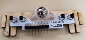
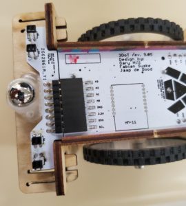
Before we cover the steps for assembling the shield, it is important to note the orientation of specific parts. Figure 1 shows the top of the PCB that will be facing the user when looking down at the robot. Figure 2 shows the bottom of the PCB that will be facing the ground or surface that the robot is on.
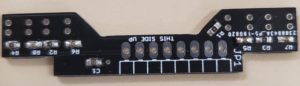
Figure 1: Top view of IR Shield
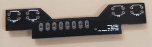
Figure 2: Bottom view of IR Shield
The outlines on the bottom side of the IR shield indicate the orientation of the IR sensors that will be placed there. It is slightly hard to see but there is a small dot in the top right corner of each rectangular outline. This will match up with the rounded edge on the IR sensor. Make sure to follow this orientation or else the sensors will be placed backwards and cause the output to be incorrect. Do not place the IR sensors into the PCB just yet. We will take care of that towards the end to make the assembly easier.
The eight pin connector can be placed in various orientations depending on the desired height from the 3DoT board. It can be level with the board, slightly above, or slightly below. For the 3DoT starter kit, it was intended to be level with the board, so the connector should be placed as shown in Figure 3. Make sure that it is flush with the shield as seen in Figure 4.
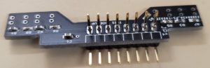
Figure 3: Connector Orientation
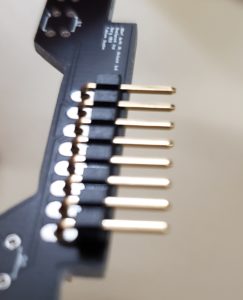
Figure 4
With that out of the way, we can proceed with the assembly.
Assembly Procedure
The first step of assembling the IR shield involves soldering the eight pin connector and confirming that it will fit properly in the robot. Make sure that it matches the orientation shown above. It is recommended to solder only the outside pins on both sides to make it easier to fix if the connector is not flush with the board or angled incorrectly. Make sure to clip the extended legs. Once that is all done, you can check if the IR shield will fit by following what is shown in Figure 5. Note that the drawing has the robot upside down and that the IR shield should fit into the groove that is on the caster ball.
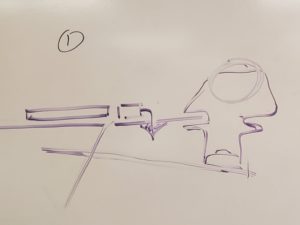
Figure 5: How the IR Shield should fit
The second step is to insert the QRE1113 sensors into their respective positions. You will only need to use the inner two sensors for basic line following, so do not place all four if you do not need to as indicated in Figure 6.
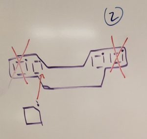
Figure 6: Inserting the QRE1113 sensors
The third step is to place everything into the robot and adjust it to the appropriate height. The reason this is important is due to the effective range of the IR sensors. If they are too high from the ground, it can result in erratic readings which will disrupt the line following algorithm. One solution for this is to use the wood shelf above the IR shield as a guide. As shown in Figure 7 and 8, if the legs of the sensor are touching the wood, there is a small enough gap to ensure that it will work properly.
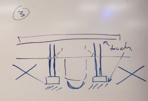
Figure 7: Adjusting the Sensor Height
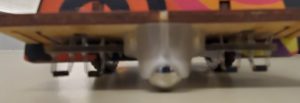
Figure 8
The final step is to carefully remove the IR shield without moving the sensors and solder them in place.
It is highly recommended to check if there are any problems with the IR sensor not working by looking at them with a cellphone camera while the IR shield is powered. The cellphone camera can detect infrared light as a slightly purplish light that is coming from the sensor as shown in Figure 9. If you do not see it after moving the camera back and forth past it, you may need to replace the IR sensor. There could be issues with the IR emitter, in which case, the sensor will not provide accurate readings.
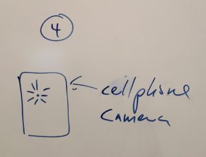
Figure 9
Once you have completed everything, it should look like the figures shown below.