Mission, Systems and Test Resources
Mission, Systems and Test Resources Overview
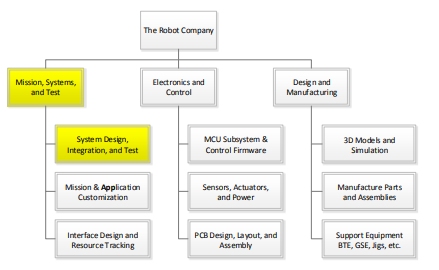
System Design, Integration and Test
Task Summary:
- Define WBS and PBS
- Define Level 2 System/Subsystem Requirements
- Interface Control Document (ICD) if applicable to your project
- System Electronic Interface Design
- System Software Interface Definition
- Cable Tree
- Grounding Strategy
- Manage system resources
- Generate verification and validation test plan
- Build summary verification and validation checklist
- Look for the Intangibles
System Design
The first task will be to work with each project manager to define unique WBS for each project. Working from the WBS and subsystem engineers, define the PBS.
Requirements
Working with the project manager, help develop level 1 program and project requirements. The project manager is ultimately responsible for generating Level 1 program requirements. Working from the level 1 requirements, and with the subsystem engineers, write the level 2 system and subsystem design requirements. Subsystem engineers are ultimately responsible for the generation of subsystem requirements.
Integration and Test (Requirement Verification and Product Validation)
Working with customer and each system engineer, develop a product requirement verification and validation test plan. This plan includes the tests to be conducted to verify requirements and validate the design. Avoid qualitative definitions like “visual inspection.”
Look for the Intangibles
Finally, a good system engineer looks at the project as a “complex system” and how it might fail or not meet customer expectations during the mission (Project Validation). This is a critical part of ConOps (Conceptual Operations) whose purpose is to discover holes in the definition of the design (the intangibles) before the start of the mission.
Case Studies
Here are some examples of ConOp failures.
A vacuum system for use in a lab might be defined in millimeters of mercury (mmHg), but once the machine is built the noise generated (decibels) makes it useless for use in a lab environment.
The stability of a walking robot might be defined by the impact of a rod of radius r (cm) located at a given distance d (cm) at height h (cm) from the robot, with mass m (kg) moving a velocity v (cm/sec) for a period of t seconds. The robot is designed to pass this test, only to fall over if a lesser force is applied. So the robot passes the defined test but fails the spirit of the requirements.
The field-of-view (FOV) of an articulating camera mirror system mounted on a rover is not defined. On the day of the final half of the camera’s FOV is the floor.
A pan and tilt subsystem is designed and tested to meet FOV requirements only to discover when mounted on the spider robot that the pan and tilt subsystem impacts the leg servos when panned down.
A large capacitor on a PCB was designed to close to an IR sensor connector preventing the sensor from
being plugged into the robot.
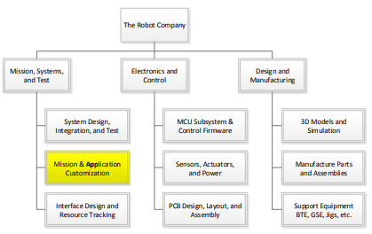
Mission and Application Customization
Programming is not a traditional role for a system engineer, but moved to this level to focus additional attention onto this too often forgotten area.
Task Summary:
- Configure mobile device App
Configure the application software required to remotely control the robot. Control may be done from a PC and/or cell phone (Android or iPhone) application. If no off-the-shelf application exists to remotely control your robot, it will be necessary to generate this code. If the project falls within this category, it will be useful to have a background in programming in one or more high level scripting languages like Processing, HTML 5, Java, or MATLAB.
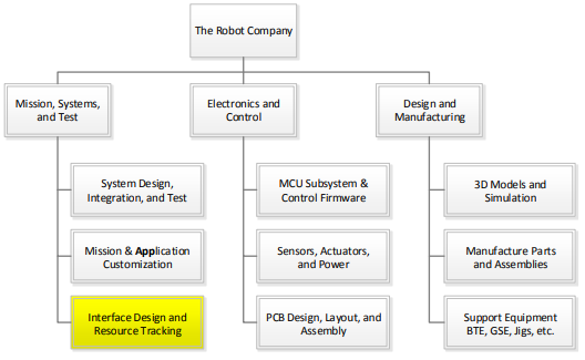
Interface Design and Resource Tracking
Task Summary:
- Document System Interface Design/System Block Diagram
- Document Interface Design Matrix
- Power distribution tracking 3Dot resources and PCB/sensor usage
- Interface control document
- Documenting system resources
System Electronic Interface Design
Working with the electronics and control subsystem engineer(s) within each project, document the System Interface Design, which includes the System Block Diagram and Interface Design Matrix.
Power Distribution Strategy
The system engineer, working with the electronics and control and manufacturing engineer, is responsible for defining the power distribution strategy (star and/or multipoint) at the PCB and System level.
Interface Control Document (ICD)
In some cases, projects will be interfacing with another project. Fall ’16 examples include the Prosthetic Arm (Wednesday class) to the Prosthetic Hand (Thursday class) and the Pathfinder Solar Panels (Wednesday class) to the Pathfinder Chassis (Thursday class). For these projects, the systems engineers will work together to write an ICD documenting the electrical connectors and cabling, power, mechanical, and other interfaces associated with the integration of the two projects. Work closely with MST counterpart in other class section, project managers for each project, and president from each class to ensure ICD is being followed. Encourage joint project meetings throughout the life of the project to help maintain communication between groups.
System Resources
Manage all applicable system resources. Resource management typically includes, but is not limited to, mass and power. For example, on a spacecraft, Field-of-View is a resource. When reporting to management, please include margins and contingencies. Margins are applied based on uncertainty in a given line item. Contingency is applied across the resource and is a function of the system resource budget minus the expected value and total margin. Resource reports should be updated on a periodic basis, typically defined by the president. As a rule of thumb, resource reports should be updated every other week and included in the meeting minutes.


