Commands and Telemetry Behind the Scenes
Table of Contents
This and future chapters looks at Arxterra communications from a developer’s perspective. Specifically, this material is intended for developers interested in extending the capabilities of the Arxterra platform and firmware included in the 3DoT Library. For example how to implement a Mars rover with 6 DC motors in place of 2 DC motors assumed by the software. Before we begin you may want to review Arxterra’s three operating modes as described in Section 03 – 1 “ Arxterra Operating Modes.”
All commands and telemetry are implemented as packets, so we will start there.
Figure 12.1: Choosing control mode
Packet Structure
The structure of command and telemetry data packets are similar. The key difference is the Packet ID. Arxterra command packets always start with the byte A5 versus a telemetry packet which begin with the byte CA.
After the packet ID both command and telemetry follow the same order, from left to right, with the following components: Packet ID, Packet Length, Telemetry ID, Data, and LRC byte as shown in Figure 12.3 for a Telemetry Packet. A packet is realized as an array of bytes. An example of a telemetry packet would be: CA 03 0E 03 A0 64.
Figure 12.2: Command packet ID.
Figure 12.3: Structure of telemetry packet.
Packet ID: All packets will have 0xA5 or 0xCA as the Packet ID. For example, 0xCA indicates the start of a telemetry packet. In other words, when the control panel decodes incoming data packets sent by the 3DoT, it starts with reading the first element in the array-formatted data packet. The decoder will then know that the elements following 0xCA will be telemetry data.
Packet Length: The packet length is the number of bytes following minus the LRC byte. The value the packet length element holds is essentially the byte size of Command or Telemetry ID and Data. After the decoder finishes reading the Packet ID, the decoder will process the packet length value. This value lets the decoder know the number of bytes to process as data to be analyzed.
Command/Telemetry ID: The command/telemetry ID is an 8-bit code identifying the type of command or sensor data contained in the packet. Refer to the Command and Telemetry ID table.
Data: Depending on the type of command or sensor, the ID byte is followed by some number of bytes. This varying-sized array provides the command parameter or sensory data.
Longitudinal Redundancy Check (LRC): The LRC byte, is basically a check of the entire packet. The LRC value is generated over the entire packet. the LRC byte is calculated by taking the XOR of each 8-bit binary value before this byte (LRC Byte = Packet ID Packet Length Command ID Parameter [0:N]). The easiest way to calculate the LRC Byte is through using the XOR checksum calculator. The detailed summary of calculating the LRC Byte can be found in Section “12 – 5: Calculating the LRC Byte.” One responsibility of the command (3DoT firmware) and telemetry (ArxRobot App) decoders is to confirm that no errors were introduced as data was transmitted or received.
Quick Summary of Packet Bytes
- Packet ID 0xA5 or 0xCA indicates the start of a command or telemetry packet
- Packet length (N) is the number of bytes following minus the LRC byte
- ID is an 8-bit code identifying the command to be executed or telemetry channel to be processed.
- ID byte is followed by some number of bytes
- The Longitudinal Redundancy Check (LRC) byte is generated over the entire packet
Command and Telemetry IDs
Arxterra’s built-in command packet IDs can be found in the Config.h file in the source folder (src) within the Robot3DoTBoard folder (Arduino libraries Robot3DoTBoard src). You can open the Configure.h file in programs like ATmel Studio and Notepad++.
Figure 12.4: Command IDs.
Looking at Figure 12.4, we see our built-in Commands, introduced in Section “06 – Built-in Commands.” Following each command is its assigned ID number. As shown in Figure 12.5, this “command ID” is the third byte received by the 3DoT firmware. Remember, the first byte for all command packets is A5. I know this can be confusing.
| Command Packet ID = A5 | Packet Length | Command ID | Parameter [0:N] | LRC Byte |
Figure 12.5: Command Packet.
Telemetry IDs
Along with the list of Command IDs (Figure 12.4), there is a list of included Telemetry ID definitions as shown in Figure 12.6.
Figure 12.6: Telemetry IDs
Like the commands, each telemetry channel has a unique identifier (Telemetry ID). A 3DoT generated “telemetry packet” ID is always hexadecimal CA, while the “telemetry” ID is the third byte received by the 3DoT firmware.
| Packet ID = CA | Packet Length | Telemetry ID | Parameter | LRC Byte |
When dealing with telemetry, the Packet ID is 0xCA and usually contains only one parameter. Furthermore, the telemetry string sequence does not have to be inputted into CoolTerm. In fact, CoolTerm will automatically display the telemetry sequence when the board is connected. When working with commands, the 3DoT board is waiting for an input from CoolTerm in order to execute that command. However, when dealing with telemetry, the board is polling this data within a “loop()” method and sending it to the ArxRobot App (Bluetooth serial bit stream) and/or CoolTerm (USB serial bit stream) when certain criteria are met.
In the next section, we will see how these identifiers give us visibility into what is happening as commands are transmitted and sensor information is received. For more information on the IDs and their purpose, refer to this spreadsheet for more details on each Telemetry ID.
Command Packet Example – Move Forward at Half Speed
For commands, the packet ID is A5, the packet length is the total length of the command ID plus the number of parameters (the easiest way to think of this is the number of parameters in the command plus one). Lastly, the LRC byte is calculated. In this example, the robot is commanded to move forward with the speed of both motors set at 50%.
| data[i] | i = 0 | i = 1 | i = 2 | i = 3 | i = 4 | i = 5 | i = 6 | i = 7 |
| Packet | A5 | 05 | 01 | 01 | 80 | 01 | 80 | A1 |
data [0] = Command Packet ID
data [1] = Packet length w/o parity byte (N = 05)
data [2] = Command ID = Move
data [3] = Left Motor Forward
data [4] = Half speed (128/255)
data [5] = Right Motor Forward
data [6] = Half speed (128/255)
data [7] = LRC byte
Telemetry Packet Example – Command Exception Code
Starting from the Move example completed in Section 12 – 3 “Command Packet Example.” If we had sent this command packet with an LRC code of 00, the command handler would have transmitted the following telemetry packet.
The first element that is processed is CA. Since the first byte is the Packet ID, the decoder will take this and analyze the type of data packet it has just received. In this case, the value is CA which denotes it is a telemetry packet.
The next element being processed will then be 03. This element in the telemetry packet array is the Packet Length. For this example, “03” tells us that the packet is a size of 3. This lets the decoder know to process the next 3 bytes as the data packet. The next three values are then taken into account as the data packet for this telemetry packet underlined above as: 0E 03 A0.
Even though a data packet consists of both the telemetry ID and data, they will be analyzed at the same time. The first element of a data packet is always the telemetry ID. In this example, the telemetry ID is 0E. By looking at the telemetry IDs in Figure 12.6, “0E” refers to the Exception ID. The Exception ID is called by the 3DoT command decoder software when there has been an error with the command that the user has just sent. However, the kind of error that has occurred cannot be determined just by looking at its telemetry ID. In this case, the telemetry ID is followed by two bytes known as the data components: 03 A0.
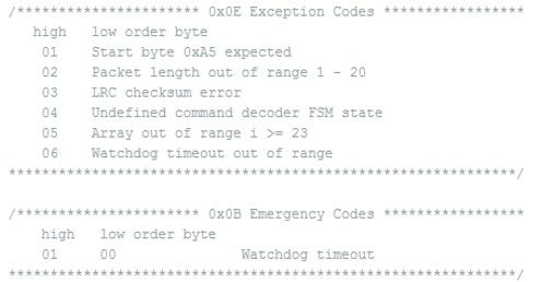
We can think of data as the arguments of the Exception ID, there is a sub table provided below the Telemetry table in the Config.h file (Figure 12.7) that explains each type of exception error code. For this example, the first argument received is 03 which is explained to be and LRC checksum error. This explains that the purpose of this telemetry packet is to say that the LRC byte expected from the microcontroller is not the same as the one the user sent in the command packet. For the case of an LRC checksum error, it is followed by a 2nd argument – the LRC byte the decoder expected. In this example, what the microcontroller decoder expected as the LRC byte is A1.
The LRC code for the telemetry packet is 64. How this was computed is covered in the next section.
Figure 12.7: Error exception codes.
Calculating the LRC Byte
The Longitudinal Redundancy Check (LRC) is the byte at the end of a command packet used to verify if there are errors present. As discussed in the Technical Training Series document, Arduino Programming, an LRC Byte is created for an entire packet and offers a parity check.
If you are working with CoolTerm, the simplest way to discover the LRC code is to send the string with a LRC byte of 00 as demonstrated in the telemetry example (Section 12 – 4 Telemetry Packet Example). As shown in this telemetry example, the command handler will return an error code with the expected LRC code. Another easy way to calculate the LRC Byte is through the use of an XOR checksum calculator. In the next section, we will take a look at how the LRC is generated and how you can calculate the LRC code by hand.
How to Calculate LRC Byte by Hand
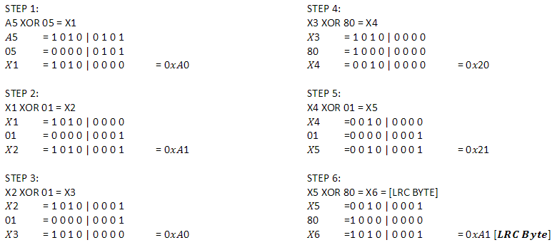
The LRC Byte is calculated by the use of XOR Logic. Each Byte is “XOR’d” from left to right. We will take our example from the Section 12-4 “Command Packet Example”, shown below is the MOVE command (0x01) sent by the ArxRobot App.
| Packet | A5 | 05 | 01 | 01 | 80 | 01 | 80 | [LRC Byte] |
How to Calculate LRC Byte with Windows Calculator
The LRC Byte the Arxterra app is sending can be calculated using a Windows desktop calculator. First, open the desktop calculator and set it to “Programmer” view as shown in Figure 12.8.
Figure 12.8: Windows desktop calculator set to “Programmer” view.
The “Programmer” calculator view should look similar to the one shown in Figure 12.9.
Figure 12.9: “Programmer” calculator view.
Select the following options on the calculator shown in Figure 12.10 below:
Figure 12.10: Calculator settings used to calculate the LRC Byte.
The “Programmer” calculator is ready to determine the LRC Byte. Using the “Programmer” calculator will no longer require each bit to be written out. For example, selecting “A5 XOR 05 =” should produce a result of “A0”.


