Inductive Sensor Issues and Fix – Ugly Blues
Introduction:
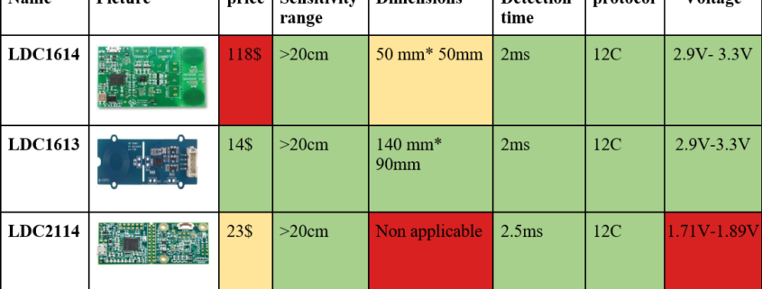
Inductive sensors can be tricky. For this project, we used the LDC 1612 inductive sensor. This is a 10-bit, 2 channel, inductive sensor that runs over I2C. For testing, I used the SEEED Studio “Grove – 2 Channel Inductive Sensor”. This sensor incorporates the LDC1612 and even comes with an accompanying library file that works with the 3dot. All testing worked flawlessly with this breakout board. However, trouble came during the manufacturing of our PCBs. There were 2 main problems, the library no longer worked and when I tested with a different “working” library, the values the LDC sensor gave seemed to be random. Both of these issues I was able to fix are described below.
Coil design is an Art:
It turns out my coils were not identical to the Groove sensor. I had to use a thicker trace value for Oshpark to be able to create my PCB and by doing so, I changed the characteristics of the coil. To design the coil I used TI’s coil designer which can make compatible coils for the LDC sensor(it is a TI sensor). This wasn’t the problem, the problem was the capacitor in parallel with the coil. The groove sensor used a 100pF capacitor and with my coil the values given by the sensor were unstable. So with a lot of testing, I found a suitable value of 47pF. Keep this in mind if you want to use this sensor, try to make it exactly the same as the Groove sensor to minimize any problems with the coils.
https://webench.ti.com/wb5/LDC/#/spirals
https://www.ti.com/lit/an/snoa930b/snoa930b.pdf?ts=1620945473204&ref_url=https%253A%252F%252Fwww.google.com%252F
LDC1612 Libraries:
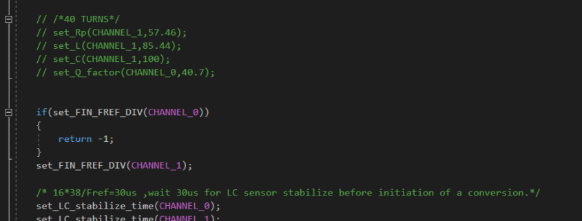
So my sensor would not communicate with the Groove sensor library. After a long time searching I found another library written by a physics professor to test inductors for his class. This library did work but it was very “bare-bones” and did not have a dual-channel mode, something I needed. The reason my front shield did not work was because I used the internal cyrstal oscillator of the LDC sensor while the groove breakoutboard used a physical component added to the board. Since this device was I2C. I need to initialize it to use the internal crystal instead. The fix can be seen here:
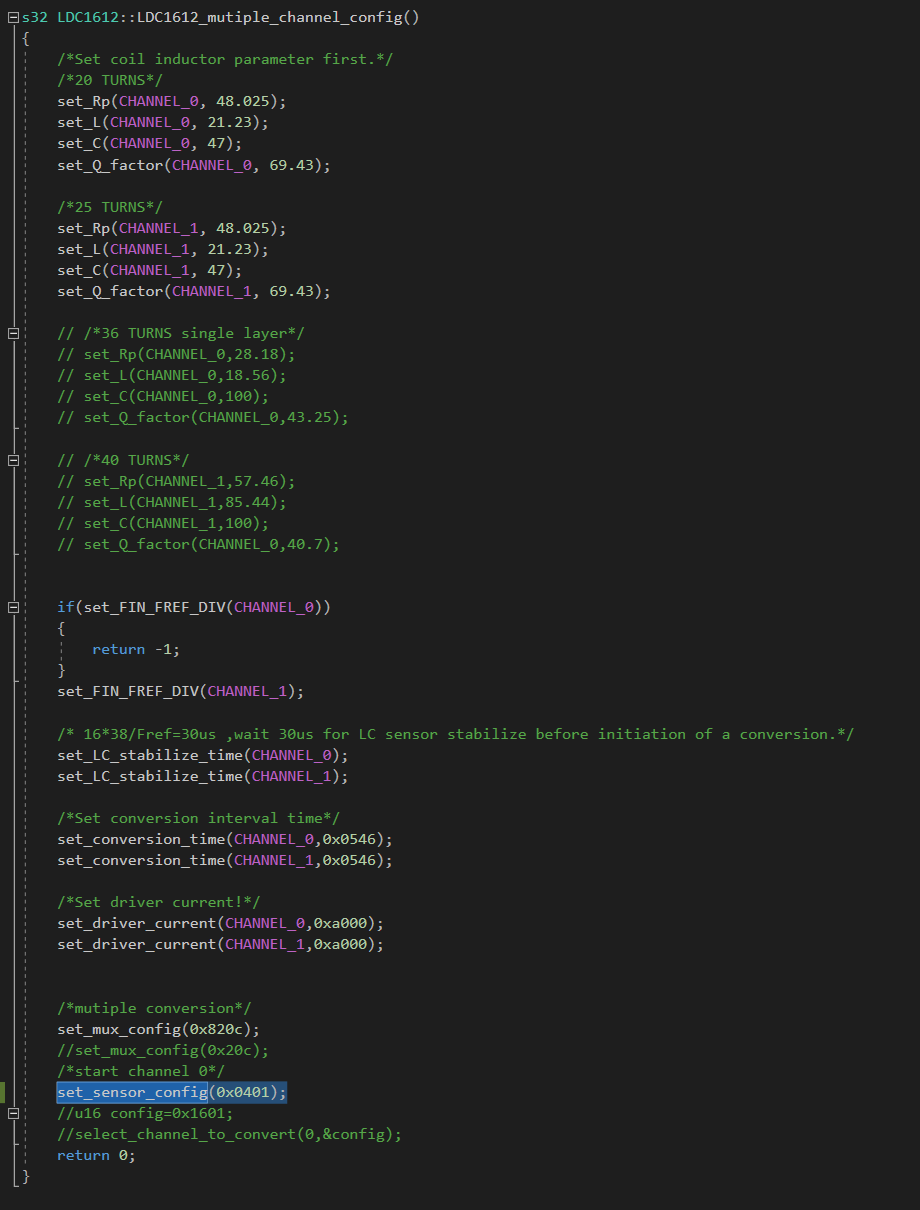
This code is in the “Seeed_LDC1612.cpp” in the Arduino library under the Multichannel config function. By changing the highlighted value to 0x0401 from 0x1601 the internal oscillator will be running the chip. This coincides with the part of the LDC datasheet:
We are changing bit 9 from 1 to 0 which enables the internal oscillator. I also changed bit 12 from 1 to 0 which gave me more consistent readings. I hope this helps someone!
Boost System Design – De Robot
Introduction:
The boost system for the De Robot project is intended to temporarily speed up the robot on straight parts of the maze. By doing this we can save some time in the maze and therefore get more points while solving the maze. To do this we are going to use a 12V boost converter to charge a supercapacitor. By controlling the output of the supercapacitor by switching MOSFETs, we can push the voltage into the motor controller on the 3dot, therefore temporarily using 12V to power the motors. However, the 3dot runs on 2 different voltages, 5V and 3.3V, so adding 12V to the system needs to: 1. Create 12V, 2. Charge a suitable supercapacitor, and, 3. Be able to switch the output of the supercapacitor on and off.
Creating 12V:
Since the 3dot has a pin for taking the raw battery voltage(~4.2-3.0V) we can take the direct output of the battery for our 12V boost system. Boost converters, more specifically switching boost converters, can be “finicky”. Meaning that the PCB design and component choice need to be very specific to operate correctly. Luckily Texas Instruments makes an online tool for the schematic design and component choice, additionally, following the PCB design guidelines in the datasheet for the boost converter chip we can design a suitable system. The tool is called Webench Power Designer(https://www.ti.com/design-resources/design-tools-simulation/webench-power-designer.html) and by putting in the parameters we want it will generate a lot of circuits suitable for the job. My requirement for choosing which one to use was: 1. Cost, 2. Efficiency, and 3. The simplicity of the circuit. The simpler circuit will make things like PCB design much easier as there are fewer components and therefore, fewer traces. I chose this design:
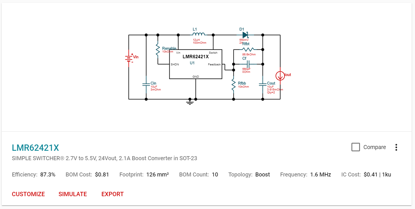
This design had a lost cost BOM(bill of materials), a decent efficiency. and the simplest schematic of all the designs. Also using the BOM I was able to find many of the components on Digikey directly, speeding up the part ordering process. Some parts like the inductor and the capacitors were not on Digikey but with the specified parameters of each part I was able to find equivalent parts.
Charging a suitable supercapacitor:
Since the boost system only needs to boost shortly we didn’t need a super high capacity capacitor. Additionally, a very high capacitance would take longer to charge therefore lowering the number of times the boost could be used. So we settled on a 1F 27V supercapacitor. Now to charge the capacitor I looked at typical battery charging circuits. They tended to share one thing in common. They are measured by the current of their output rather than voltage. This is perfect for battery charging as batteries are typically charged with the constant current rather than constant voltage. Supercapacitors could be charged either way, but charging it like this made things feel moderately safer. So to charge the supercapacitor all we had to do was add a current limiting resistor to not overwhelm the current output of the 3dot then hook it up to the output of the boost.
Switching the output:
Before we decide how to turn on and off the boost system we first had to look at the 3dot schematic to find out how we can provide voltage into the motors. I am looking for 2 things, how the motors are getting power, and how I can protect the 3dot from the 12V.
Motor driver:
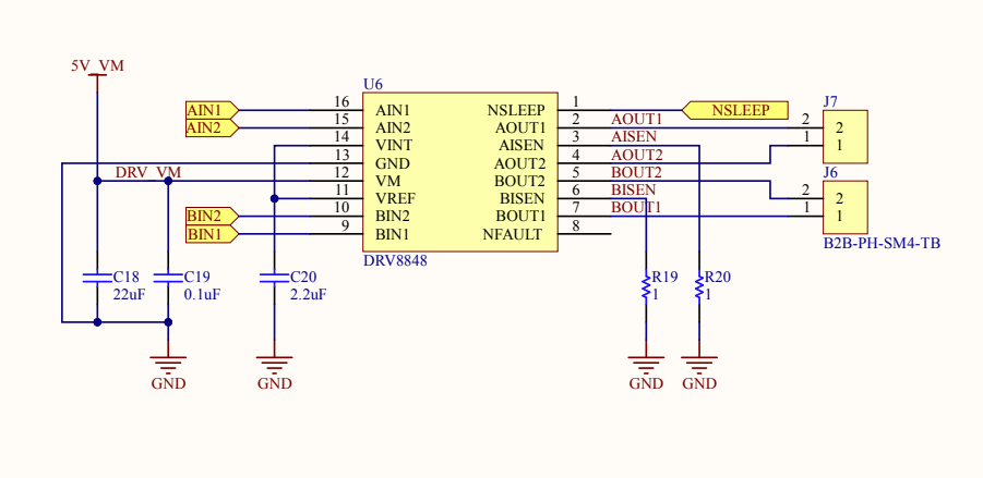
The 3dot uses an H-bridge motor driver called the DRV8848 to control and power the motors. According to the datasheet of this DRV8848, it can accept an input voltage from 4V-18V. This means we can switch the power to the H-Bridge without boost output and be able to use PWN while boosting! But first, we need to find how we can switch the power.
Protecting the 3dot from the 12V:
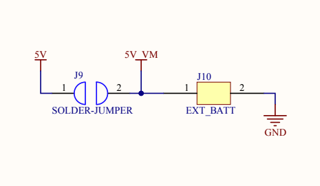
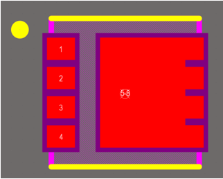
This picture here shows a solder jumper on the board. To keep things short, on the V10 version of the 3dot the 5V is the output of the onboard 5V boost converter and 5V_VM is the power source only used for the H-Bridge. This means but desoldering the solder jumper and adding in a Schottky diode we can isolate the supercapacitor output to only the H-bridge and keep the 3dot safe.
Note: The pinout says 5V_VM is the power pin on the servo header but this is not correct according to the schematic.
High Side Switch:
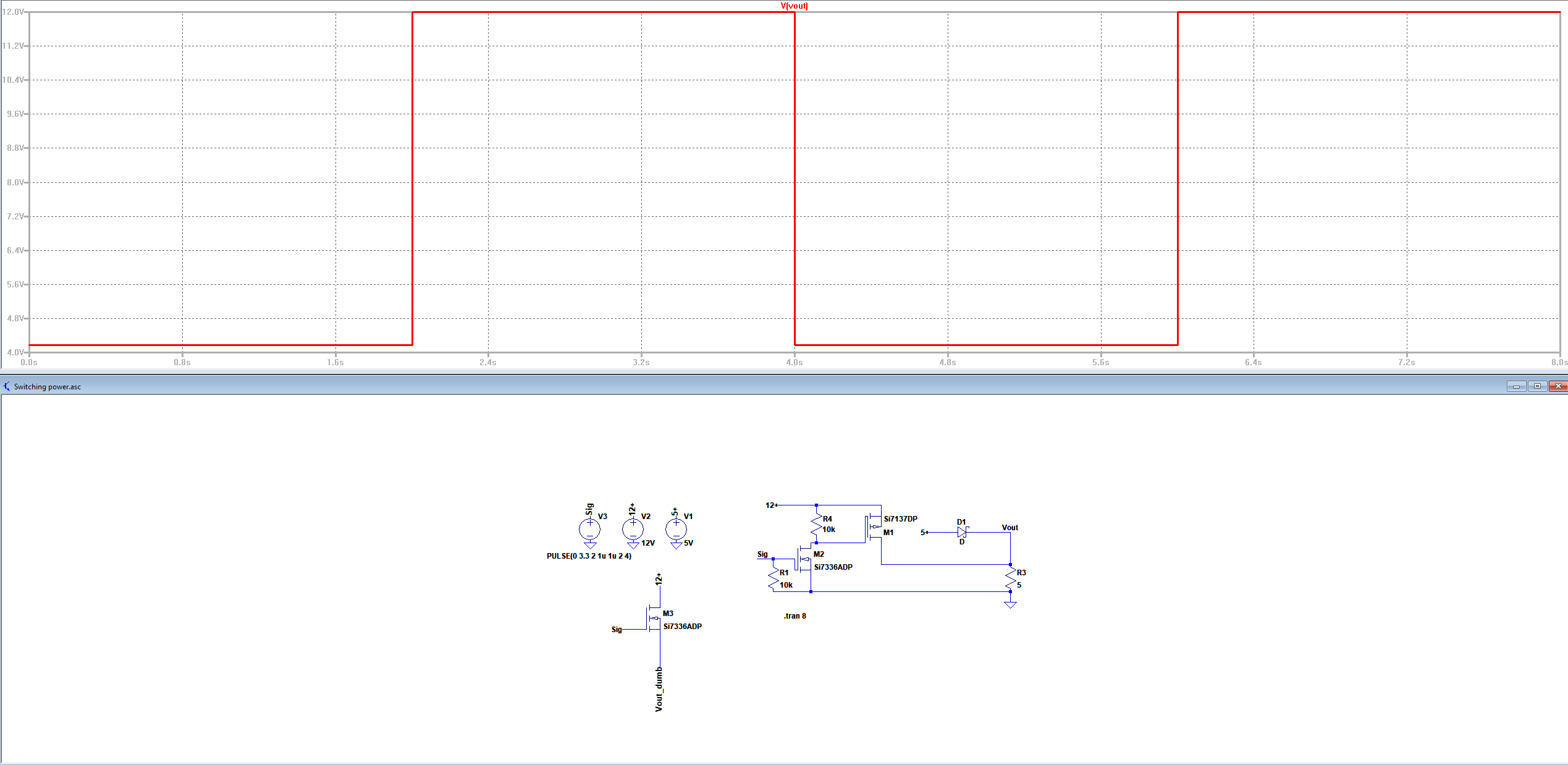
There are many ways to switch one voltage with another, relays, analog switches, etc. I chose what seemed to be the simplest to implement and best performing in this case. By using a P-channel and a N-channel MOSFETs with suitable resistors we can make a high side switch with the other MOSFET driving the gate of the high side transistor. This can be seen in this LTSPICE simulation:
Finally, we can add all these things together to create the final EAGLE schematic and PCB.
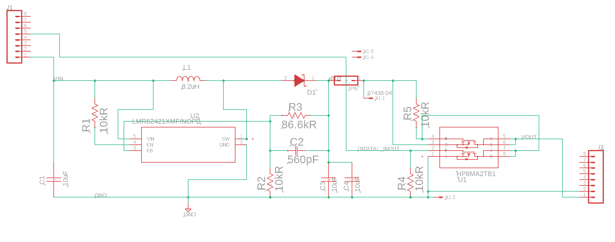
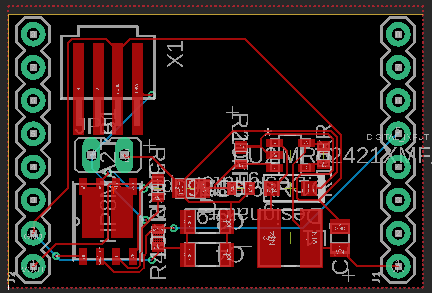
Note: The current limiting resistor is not included as it was added off-board. The final PCB design was changed to fit all the parts and make it easier to manufacture. Please refer to De Robot’s top shield blog post for the final top hat design.