Camera Stabilization Gen 1
Author/s:
Saqr Almuraikhi ( Project Manager)
Gabriel Ayala (3D Modeling and Manufacturing)
Danny Jorquez (Power consumption and Motor Drivers)
Andrew Stumpf (Software Engineer)
Table of Contents
Executive Summary
Providing a Platform that can Accommodate a GoPro Hero 4 Silver and keep it stabilized but Keeping it Compact, affordable, and easy to use is our objective. A movie grade vehicle stabilizer such as the ProAim Action Tubular Car Mount is upwards of $2500+ while our Projected Cost for the stabilizer is $457. And the form factor is small so it can be carried anywhere and doesn’t take much space on the vehicle that it’s mounted on compared to the movie grade stabilizer that is as big as a 9-year-old child. Our Platform is very simple even a 9-year-old can use it, basically attach the platform to the vehicle and press the start button on the GoPro Hero 4 Silver.
Program and Project Objectives
Program Objectives
The objective of The Camera Stabilizer team is to provide 2 stabilizers that will carry cameras that are going to be capturing the Robodog and the course. The Camera stabilizers are going to be mounted on the Comm Bot one facing forward to stream the course and the other camera will be facing sideways towards the dog to provide a live feed of the Robodog on its mission. Each Student Shall Create and design a custom PCB.
Mission Profile
The Mission Profile is To Prepare 2 Stabilizers that are going to be able to operate at speeds of 1.8 meters/s traversing the course which is going to be in the Japanese Garden at CSULB the stabilizers will be tested outdoors during the day on December 14th and be fully Operational at temperatures of 7.22°-18.3°Celsius. Both stabilizers are going to have 3 axis Pitch, yaw, and roll, the stabilizer shall be less than 8 inches in height and it will not interrupt the solar panel operation. The stabilizers will use 15 watts at 24v power is discussed with the solar panel team and commbot team.
Project Features
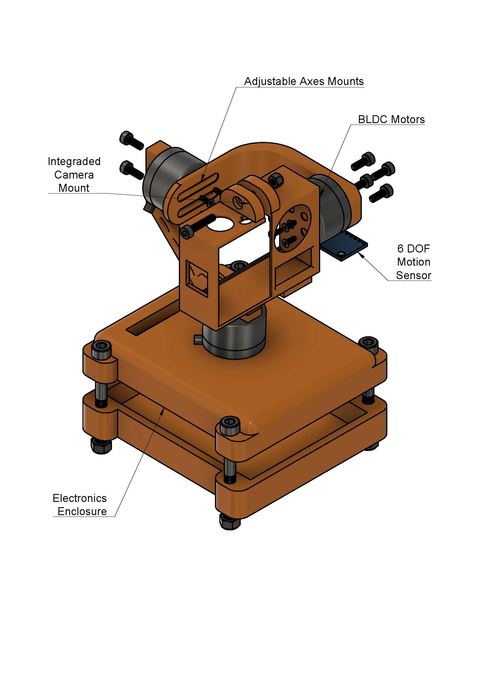
Figure 1-1 Project mechanical features
Our Project is made up of 3 motors connected using 3d Printed arms all stationed on top of a base that has the electronic parts enclosure that contains the Custom PCBS and armcortex m7 and at the top has the camera holder and at the bottom of the camera is the holder is the housing for the imu.
Requirements
Engineering Standards and Constraints
Standards Development Organizations
A standard is a document that defines the characteristics of a product, process, or services, such as dimensions, safety aspects, and performance requirements.
- ASTM (American Society for Testing and Materials)
- IEEE (Institute of Electrical and Electronics Engineers)
- ASME (The American Society of Mechanical Engineers)
- ANSI (American National Standards Institute)
- NASA Standards
- ISO (International Organization for Standardization)
- NIOSH (National Institute for Occupational Safety and Health)
- NTSC (National Television System Committee)
Examples of Engineering Standards and Realistic Constraints.
The software will be written in the Arduino De facto Standard scripting language and/or using the GCC C++ programming language, which is implements the ISO C++ standard (ISO/IEC 14882:1998) published in 1998, and the 2011 and 2014 revisions. Required exceptions to this standard can be found here.
All project Schedules shall be constrained to a completion date of Tuesday, December 14, 2021. Project completion includes documentation and materials purchased by or loaned to the project.
All robots shall be constrained to a not-to-exceed Cost of $250.
Wiring Aesthetics shall be nice and clean with the usage of terminal blocks, 100 mil contact pins, and headers, 2.0mm PH series JST connectors, and barrel connectors. Handling Precaution for Terminal and Connector will be in compliance with JST documentation.
To enhance Aesthetics, the robot shall be designed in such a way that there are no dangling or exposed wires. Connectors will be used between all electronic and electromechanical components. Jumper wires will not be used, ribbon cables are preferred;
Back of the envelope calculations and experiments shall be conducted to set the diameter of power-carrying wires. Follow the American Wire Gauge (AWG) standard when defining the diameter of power-carrying wires. This work is to be completed and documented by the CDR. All Safety regulations as defined in Section 4.3 Hazards and Failure Analysis of this document shall apply.
Maintainability: Disassemble and Reassemble of the robot shall be constrained to less than 20 minutes (10 + 10 minutes). Disassembly: The. All electronic and mechanical subassemblies and associated connectors, sensors, and actuators including motors are disconnected. A functional test of the robot is conducted after reassembly to confirm its functionality. All projects may reference a cable tree as well as an assembly diagram as necessary. This requirement is demonstrated/verified on the last day of the schedule. Projects may request a waiver with justification.
The usability of the robots shall be enhanced by adding autonomous functions and/or by use of the Arxterra phone application as dictated by the assigned mission.
Accessibility by the blind and Marketability of the robots shall be implemented/enhanced by a speaker. The speaker shall generate sound effects consistent with the type of the robot. For example, the Goliath tank would make “track” sounds, the AT-ST sound effects would mimic their Star Wars antecedent. This feature shall also be used to
The manufacturability of 3D printed robots shall be demonstrated by compliance with the 3/3/3 rule. Specifically, total print of a robot is constrained to 9 hours, with no single print taking longer than 3 hours. Projects may request a waiver with justification.
The constructability of robots shall be documented at the CDR and approved by the president of the TRC robot company. Constraints imposed by this requirement include the use of bushing or bearings in all moving and rotating parts. Interlocking Hinges with latching mechanism. No gaps greater than 1 millimeter, and immediate access to all external connectors (USB, switches).
To enhance Aesthetics, the form factor of a robot modeled on a real or fictitious robot shall be constrained by the original. For example, Goliath should be a scale model of the real Goliath 302 tank. Projects may request a waiver with justification.
One of the Economic Factors affecting our robots is return rates. To demonstrate the durability and child-friendliness of our robot a simple drop test from 1.4 meters shall be performed. The height is defined by the average height of an average 11-year-old girl.
Power to all robots shall be provided by the external battery Lithium Polymer LiPo battery. All Safety regulations as defined in Section 4.3 Hazards and Failure Analysis of this document shall apply to the shipping, handling, storage, and disposal of LiPo batteries.
Engineering Standards Applicable to our Projects
IEEE 29148-2018 – ISO/IEC/IEEE Approved Draft International Standard – Systems and Software Engineering — Life Cycle Processes –Requirements Engineering.
NASA/SP-2007-6105 Rev1 – Systems Engineering Handbook
Bluetooth Special Interest Group (SIG) Standard (supersedes IEEE 802.15.1)
Program Level 1 Requirements
- L1.01: To properly teleoperate the communications bot the Interframe Transformation Fidelity (ITF) shall be above 20 dB. The metric was obtained from Guilluy[1] and the adequate levels were determined through a tradeoff study which shall be discussed later in the presentation.
- The ITF shall be verified by recording test footage and using MATLAB for ITF calculations.
- L1.02: To maneuver the communications bot remotely the camera shall provide a first-person-view (FPV). According to Balestrieri[2], this is the best view for unmanned-ground-vehicles (UGV).
- To Prove Functionality we will use a Measuring tape and raw footage from the camera to determine if the Camera Has FPV.
- L1.03: The stabilizers shall be mounted to the communications bot Using Screws to provide teleoperation capabilities.
- To prove Functionality Applying Force to the base to see any movement happening to the base of the stabilizers. ( a waiver has been submitted to remove teleoperations capabilities)
- L1.04: The stabilizer shall be able to operate in the outdoor environment of the mission profile.
- The operation shall be verified by testing the end product.
- The stabilizers shall be powered Using a power source Shared between the 3 systems to allow for integration.
- The power supply shall be verified by testing the end product with the voltage(+current) range of the battery(multimeter).
- L1.07: Three custom PCBs shall be designed and created to meet the learning objective set by management.
- PCB design shall be tested and verified by management.
- L1.08: The camera shall conform to NTSC standards 720p at 30fps[9].
- Verified by inspection of camera Feed(Camera Specification States capability of 720p at 30fps).
- L1.09: The stabilizer shall be able to maintain a line of sight with Robodog.
- The Line Of Sight shall be verified by Using a Measuring Tape to actuate the Line Of Sight.
System/Subsystem/Specifications Level 2 Requirements
- L2.01: The linear motion blur shall be below 8 pixels. Keeping the linear motion blur below 8 pixels ensures that the ITF shall be above 23 dB.
- Linear motion blur shall be verified through analytical analysis and calculation of ITF.
- L2.02: The radial motion blur shall be below 2 pixels. Keeping the radial motion blur below 2 pixels ensures that the ITF shall be above 20 dB
- Radial motion blur shall be verified by recording test footage and calculating ITF with MATLAB.
- L2.03: The camera shall be able to stream wirelessly at a distance of 2 meters to provide a first-person view.
- The wireless streaming capabilities of the camera shall be verified by inspection of the end product.
- L2.04: The camera shall have FHD (1920x1080p) resolution capabilities. According to Balestrieri[2], UGVs require a minimum resolution of 1340x1024p for reliable perception and obstacle detection with visual cameras. To meet North American video standards the minimum resolution is FHD.
- The resolution shall be verified by inspection of recorded video used for ITF calculations.
- L2.05: The stabilizers shall be able to control yaw, pitch, and roll movements to maintain proper LOS with Robodog
- The control of yaw, pitch, and roll will be verified by inspection of the end product design.
- L2.06: The camera shall have a minimum diagonal field-of-view (FOV) of 100°. Balestrieri[2] states that a horizontal FOV of 68.2° and vertical FOV of 53.8° is optimal for the teleoperation of a UGV. To comply with North American video standards a horizontal FOV of 92.2° and vertical FOV of 60.6° were chosen which equates to a diagonal FOV of 100°.
- The FOV shall be verified by analysis and inspection of camera specifications.
- L2.07: The stabilizers shall be able to operate within a temperature range of 7.22°-18.3°Celsius. The mission shall outdoors and the National Weather Service[3] shows a mean max and min temperatures in this range for December.
- Temperature range shall be verified by exposing end product to extremes of temperature range and operating for TBD time.
- L2.08: The stabilizers shall have a height of 20 cm as to not interfere with the solar panel movements which shall also be mounted to the communications bot. The height restriction was obtained from the Solar Panel team.
- The height will be verified by a demonstration of stabilizer articulation within the specified area.
- L2.09: The stabilizers shall weigh 680g each. The weight is restricted by the payload capacity of the communications bot. The mass allocation was obtained from the Communications Bot team.
- The end product shall be weighed for verification of mass allocation.
- L2.10: The stabilizers shall have a power consumption of 15 watts at 24 volts. The power produced by the solar panel team shall be shared with the communications bot therefore the power consumption must be allocated accordingly. The power consumption was discussed and negotiated with Solar and Com. Bot teams.
- The power consumption shall be verified by testing the end product and measuring the current draw.
- L2.11: The custom PCB requirements are TBD.
- PCB design shall be verified by management.
- L2.12: The structure shall be 3D printed. The stabilizers must be demonstrated by December 14th, therefore the manufacturing method must be accessible to the team. Two of the team members have access to a 3D printer and shall accelerate prototyping and manufacturing.
- The manufacturing will be verified by inspection of the end product.
Allocated Requirements / System Resource Reports
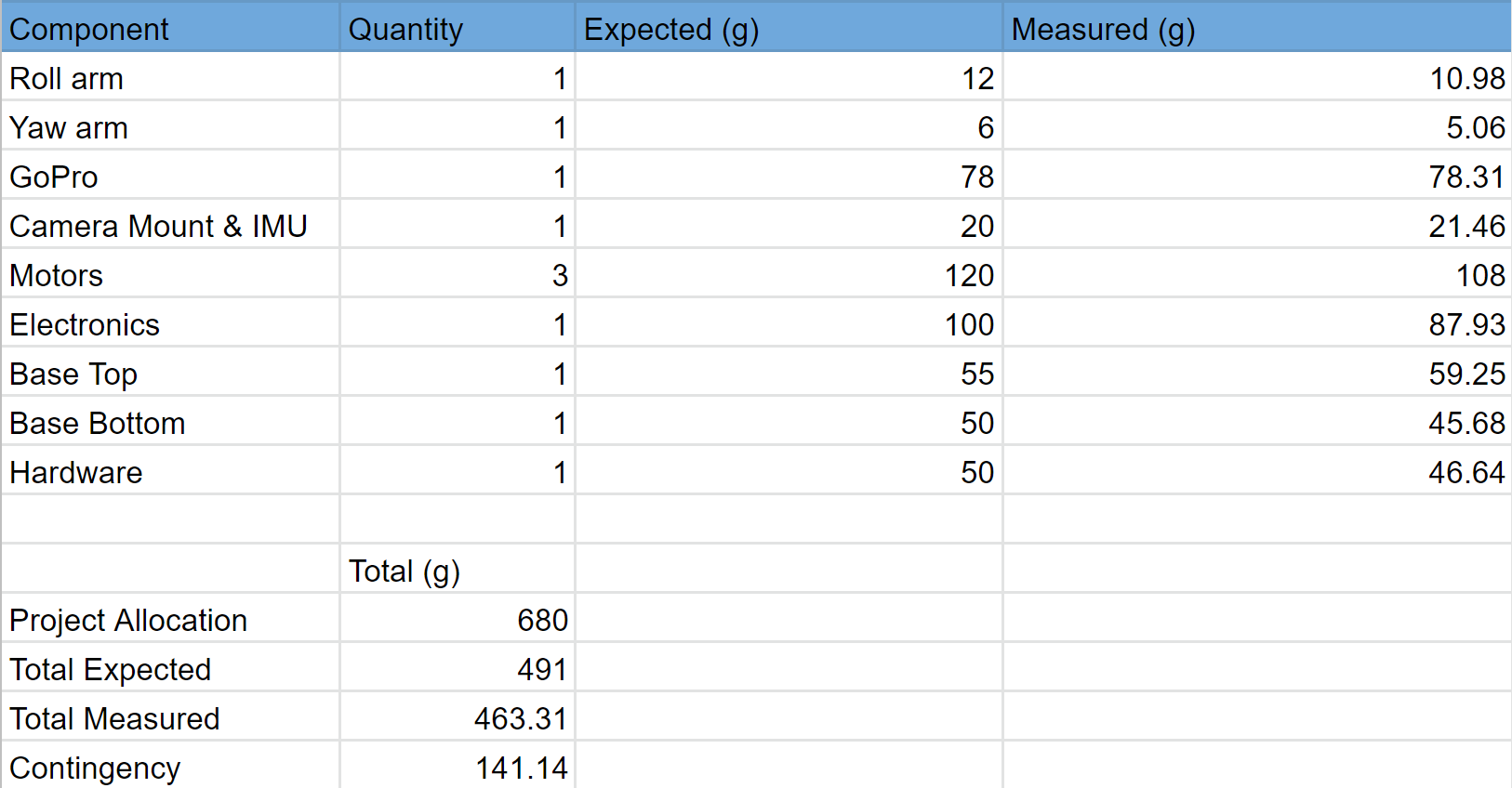
Figure 2-1 Mass Allocation
Mass Allocation
The estimated weight of the camera and motors would be supported by 3D-printed plastic. Polyethylene terephthalate glycol (PETG) filament was used to print the arms and gimbal in which the camera and motors would be mounted. The material chosen would support the allocated weight according to the tensile strength of PETG. With a total allocated weight of 680 grams, we needed to choose motors that would meet the power requirements but not exceed the allocated weight. With a total of 3 motors, our weight for the motors would not exceed 150 grams. The low weight of the motors allowed for plenty of weight for the remaining components. The electronics, such as the microcontroller, inertial measurement unit (IMU), and motor drivers weigh very little and were estimated accordingly using their respective datasheets. The remaining allocated weight would be used for the base and top into which the PCBs would be placed into. Once we received and printed all the necessary components the estimated weight was close to the measured, slightly under, which meant our project was meeting the given allocation.
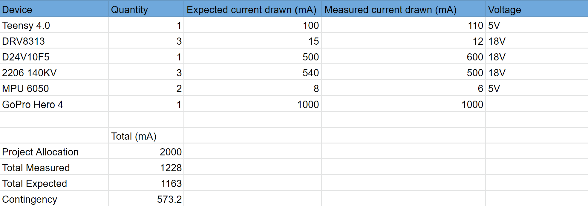
Figure 2-2 Power Allocation
Power allocation
The total allocated power was given to us by the solar team. The camera stabilizer will not exceed the maximum allocated 2 amperes at 18V. Measuring the exact amount of power that the camera stabilizer would use proved to be a difficult task due to the fact that the motors did not have power consumption in the specifications. This seemed to be a universal theme whenever researching motors that were made for camera gimbals. Using the rated revolutions per volt or KV of the motors the power consumption was calculated using T=I*Kt, where Kt=1/kV. Using the rated torque solving for the current was done using the previous formula. Estimating power consumption for the teensy 4.0 microcontroller and motors drivers was done using the maximum rated power consumption on the respective data sheets. The estimated power consumption was based upon a worst-case scenario when applicable. For example, the estimated worst-case scenario for motors is not applicable because the motors are capable of more than 100 Amps, well beyond our 2 Amp allocation.
Given that the camera stabilization does not require a fast and constant turning of the motors, we were able to keep the power consumption low enough to allocate the remaining power to the remaining components. The camera chosen has a built-in battery that would last the entire mission on a full charge. The teensy microcontroller and IMU operate on 5V, therefore a voltage regulator was implemented in order to step down the 18V to an appropriate 5V. Once all parts were acquired, the estimated current draw was slightly less than measured. The total measured current draw ensured that the allocated power was enough to power our camera stabilizer.
Author/s:
Saqr Almuraikhi ( Project Manager)
Project Report
Project WBS and PBS
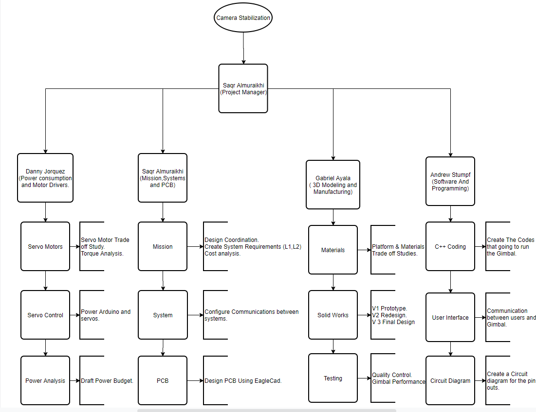
1:Work BreakDown Structure
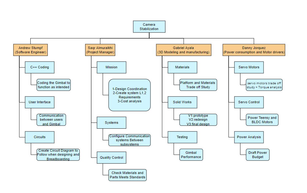
Figure 3-1 Camera Stabilization WBS
This is the work breakdown structure. Starting from the left we have Andrew our Software Engineer the structure dictates that he is handling Coding and designing circuits for our project. After that is Saqr is the Project manager responsible for documentation assigning roles creating the mission objective and profile and quality control. Further to the right is Gabriel the person responsible for 3 modelings and manufacturing his role is to design the model in solid works and pick the materials that are going to be used for the gimbal and test the gimbal. And lastly is Danny is handling Power consumption and motor drivers, his role is to keep our power usage in check and make sure to control the BLDC power usage and keep it at a minimum.
1:Product BreakDown Structure
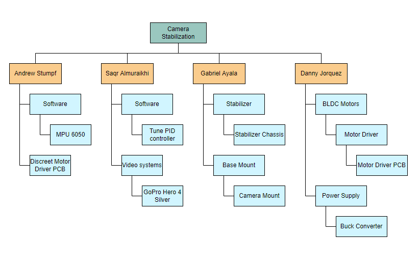
Figure 3-2 Product Breakdown Structure
This is the Product Breakdown Structure. Starting from the left is Andrew he is designing a custom PCB that serves as a discreet motor driver, Then Saqr he’s responsible to tune the PID controller, Gabriel is handling the stabilizer chassis and the camera mount, and lastly, Danny is handling BLDC motors and motors driver finally the Power supply integrating a buck converter to handle the voltage,
Cost
Author/s:
Saqr Almuraikhi ( Project Manager)
Gabriel Ayala (3D Modeling and Manufacturing)
This Table Covers all the materials and parts we needed to build our project anything that does not have an order date is things that were readily in hand.
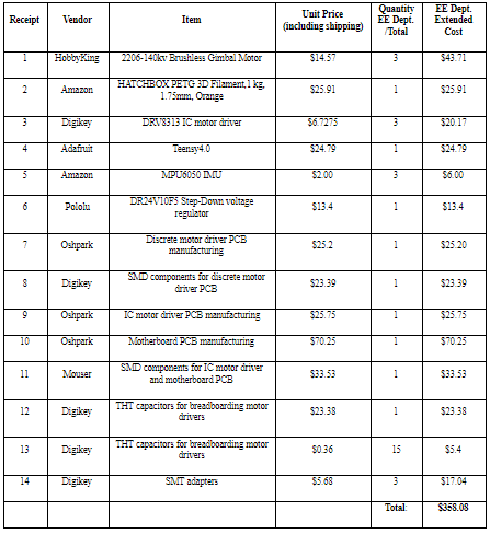
Figure 3-3 Cost analysis
Author/s:
Saqr Almuraikhi ( Project Manager)
Andrew Stumpf (Software Engineer)
Schedule
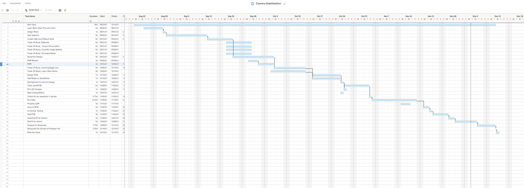
Figure 3-4 Camera Stabilization Schedule
This is the schedule with the critical path shown with the arrows, the critical path is basically what needs to be done to make progress and finish the project in the time scheduled in the mission objective, so the path starts in the first week where we figure out what we are good at and appoint roles in the project, research comes after that, we would start researching on way to figure out how we want to accomplish the mission. After figuring out the way we want to accomplish our mission we start with creating Higher level requirements to set goals to meet and objectives complete. The next step will be to start designing PCBs to accomplish another goal in the mission profile and design the first iteration of our Gimbal using solid works. Thereafter we start printing and ordering the parts needed for the project and start coding the project. Lastly, we just start testing out the V1 Gimbal and start making adjustments as we see fit to finish and assemble the final version of our Gimbal to submit on December 15th 2021.
Concept and Preliminary Design
Author/s:Gabriel Ayala (3D Modeling and Manufacturing)
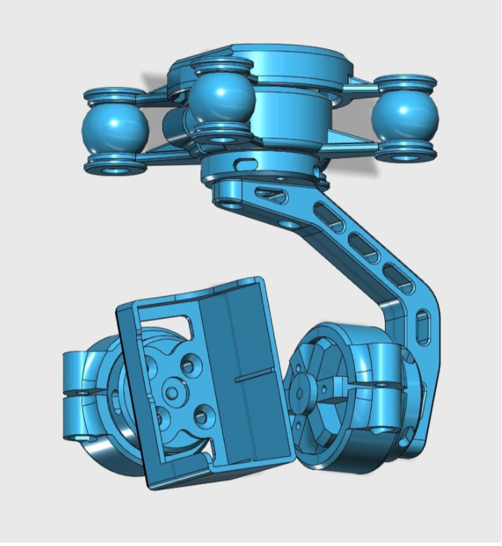
Figure 4-1 Open Brushless ModelGimbal [4]
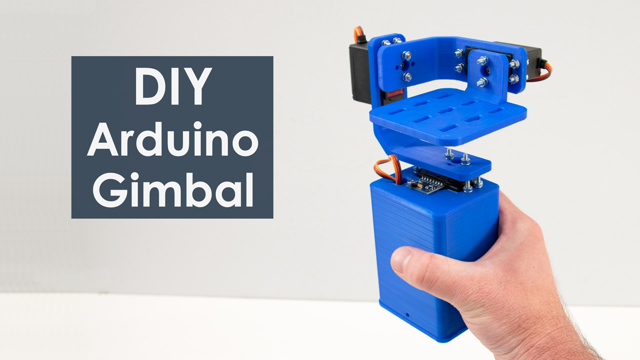
Figure 4-2 DIY Arduino Gimbal [11]
System Design / Final Design and Results
System Block Diagram
Author/s: Andrew Stumpf (Software Engineer)
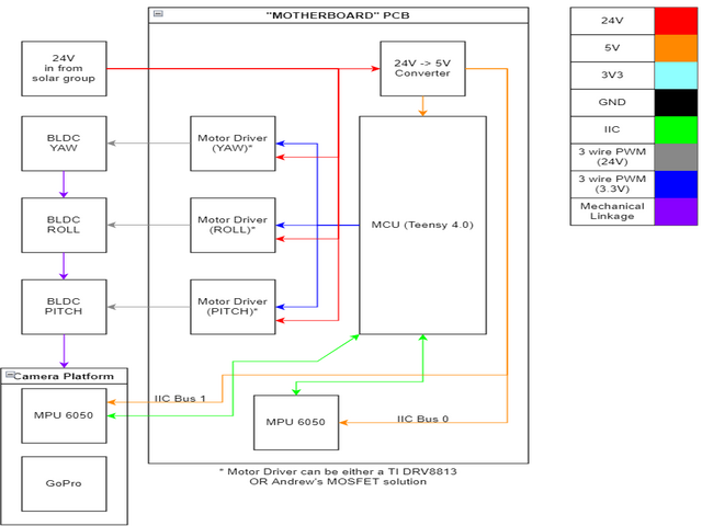
Figure 5-1 System Block Diagram
To simplify our block diagram, we decided to make a “Motherboard” style PCB for our project. Our motherboard contains our microprocessor, a Teensy 4.0, an MPU6050 IMU, and sockets for 3 motor drivers and the buck converter. We chose to create a motherboard because it allowed us to have a rigid board we could mount in the housing and because it would allow pin-compatible replacements for components. Each motor driver socket is designed to be compatible with either the TI DRV8813 or Andrew’s scratch-built MOSFET-based driver. Likewise, the buck converter is socketed, so if our first attempt doesn’t work, we can solder on an off-the-shelf solution. Aside from the motherboard, we have our 3 motors, and our second IMU, and our GoPro. The motor that is mounted to the same plastic housing as the motherboard is the Yaw motor. Its wires go directly into the main box. The other two motors are mounted on 3D printed plastic brackets, and their wires will join the “Trunk” of the harness that ends in the 2nd IMU. The MPU6050 (and the gopro) are the only components that need to move in 3 axis. As such, they need the most cable slack and the longest cables.
Interface Definition
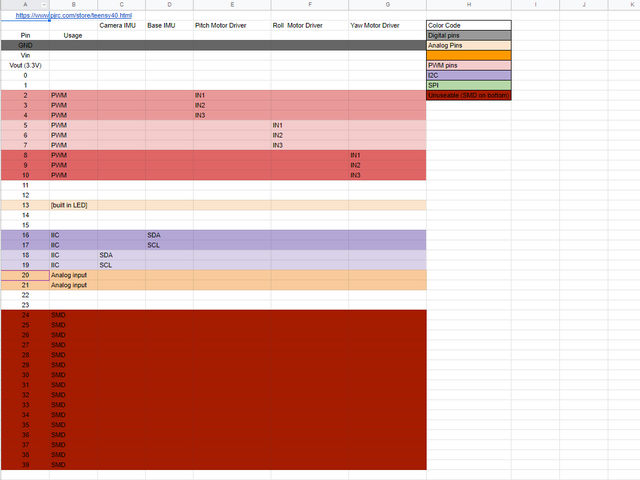
Figure 5-2 Interface Matrix
Our interface matrix was chosen to be compatible between the TI DRV8313, and a custom-made driver chip. Both motor driver solutions use 3 PWM inputs. We were limited by Teensy’s list of PWM capable pins. We chose pins 2-10 because they were all on the same side of the board, and they are all PWM capable. We left pins 0 and 1 open in case we needed to use UART or USART. We avoided using pin 13, as that’s the onboard LED pin, and it would be useful to have for troubleshooting. Because Teensy 4.0 has 2 IIC interfaces, we decided to put one IMU on each IIC interface, accounting for pins 16-19. Because we are using 2 separate interfaces, a wiring issue with one IMU would not prevent the other IMU from operating, making troubleshooting easier. Because one IMU is mounted to the same PCB as the teensy, this decision does not add any additional cabling. Pins 20 and 21 are tentatively available for Hall sensors, but we have decided against their use for the final revision. Pins 24-39 are SMD pads on the bottom of the device, and are therefore mostly useless to us.
Author/s:Gabriel Ayala (3D Modeling and Manufacturing)
Modeling/Experimental Results
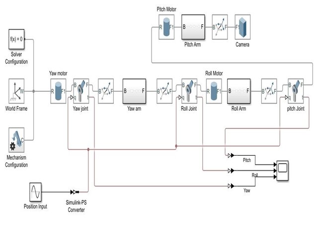
Figure 6-1 Simulink Torque Simulation
A Simscape Multibody simulation was performed to determine the actuator torque requirements and power consumption. Simscape is an addon for Simulink that allows for direct physical modeling by means of a block diagram as shown in figure #. The weight of the chosen motor would affect the overall moment of inertia and consequently the torque requirements. The variables used in the model such as motor weight, camera weight, and dimensions were varied in MATLAB to determine their effects on the torque requirements. The torque of a dc motor can be determined by equation #, which shows that the current is directly proportional to the torque. A brushless DC motor with a Kv rating of 140 was chosen because it provided the necessary torque while not exceeding the power allocation for the system.
(
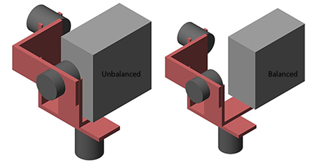
Figure 6-2 Simscape mechanics explorer view of mechanical design iterations
The simulation also aided in the mechanical design of the gimbal. The model helped prove that counterbalancing the camera with the pitch motor along the roll axis could reduce the overall torque requirements and power consumption. It also showed that the distance between the camera and motor did not cause the gimbal to exceed the allocated dimensions.
Stabilization Metric
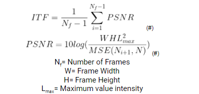
There is not a standard metric for video stabilization because the quality of video and acceptable movements are subjective. If the viewer is meant to perceive motion, then the observable movement in the video does not degrade the quality. The most widely used metric is interface-transformation fidelity(ITF), which is mostly for the comparison of software-based stabilization algorithms. ITF is the average of peak-signal-noise-ratio (PSNR) between consecutive frames. It compares the similarity between frames. The higher the similarity the higher the ITF value. The acceptable values are still subjective and must be defined by the viewer.
The acceptable ITF was determined by comparing videos taken with a GoPro at the approximate operating height of 63 cm and walking a distance of 1.5 meters. The GoPro was set to 1080p at 60 FPS with a medium field of view. Two videos were recorded, for the first video the GoPro was held relatively still while the other was purposely shaken. A still Full-High-Definition image was also used to analyze the effects of linear versus rotational motion blur. Linear and radial pixel blur were added in photoshop at increasing values until details in image were indiscernible.
| ITF | Adequate | |
| “Stable” Video | 22.22 | Yes |
| Unstable Video | 20.24 | No |
| 1 Radial Pixel Blur | 21.88 | Yes |
| 2 Radial Pixel Blur | 20.4521 | No |
| 5 Linear Pixel Blur | 24.6338 | Yes |
| 8 Linear Pixel Blur | 23.1160 | No |
Table #: ITF analysis results.
The results provided the L1.01 requirement and also supported the design choice to use a 3-axis gimbal with no linear compensation. It takes 8 times more linear pixel blur than a radial blur to cause unacceptable blurriness.
MATLAB Code
stable=VideoReader('unstable.mp4'); %creates object to read video data
frames=stable.NumFrames; %number of frames in video
value=[];
%calculates PSNR between each consecutive frame and stores in value[] array
for i=1:frames-1
    value(i)=psnr(read(stable,i+1),read(stable,i));
end
Author/s:Andrew Stumpf (Software Engineer)

Figure 6-3 Multisim Half-H Bridge Simulation
These are the simulations used by Andrew to determine the viability of using both N channel and P channel MOSFETs in combination with an NPN transistor as a level shifter. As you can see, the power dissipation is fairly low, even at a 100% duty cycle
BreadBoarding
Author/s:Gabriel Ayala (3D Modeling and Manufacturing)
Bread Boarding
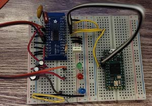
Figure 6-4 Single DRV8313 motor driver controlled with Teensy 4.0.
The DRV8313 only comes in an SMD package and therefore needed to be soldered onto an adapter for breadboarding. The breadboarding was done to ensure that the DRV8313 worked with the SimpleFOC library. The output for the three phases were connected to LEDs to ensure that each half H-bridge could be controlled by the teensy without danger of burning out a motor.


Bread Boarding
Once the functionality of the DRV8313 was confirmed, a prototype board was constructed for testing and contingency plan if PCBs did not arrive on time. The motor drivers and Teensy 4.0 were connected with headers to make them replaceable in the case one got damaged during development and testing.
Author/s:
Andrew Stumpf (Software Engineer)
Bread Boarding
Figure 6-5 H bridge and Mosfet drivers(1/2)
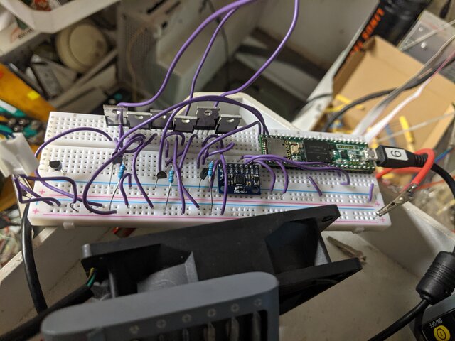
Figure 6-6 H bridge and Mosfets (2/2)
The successful parts of my breadboarding are shown in the images above. Before I started any breadboarding, I ran simulations based on someone else’s design in NI Multisim. Once I confirmed my circuit worked in simulations, I built 2/3 of it on a breadboard to keep it simple in the beginning. The image on the left is a full H bridge, like one that would be used in a standard DC motor controller. As you can see, there are only 4 mosfets, and the motor is spinning. This indicates success, at least at low frequencies. I then decided to test my full design, with all 3 1/2-H-Bridges. This is the image on the right, showing all 6 MOSFETS running off my Teensy 3.5. I don’t have a Teensy 4.0 handy, so I used what was available. This circuit was successfully able to drive a motor rated for a much higher power than the ones we will be using, so the design passed my testing.
Electronic Design
PCB Design
Author/s:Andrew Stumpf (Software Engineer)
Discrete Motor Driver (PCB)
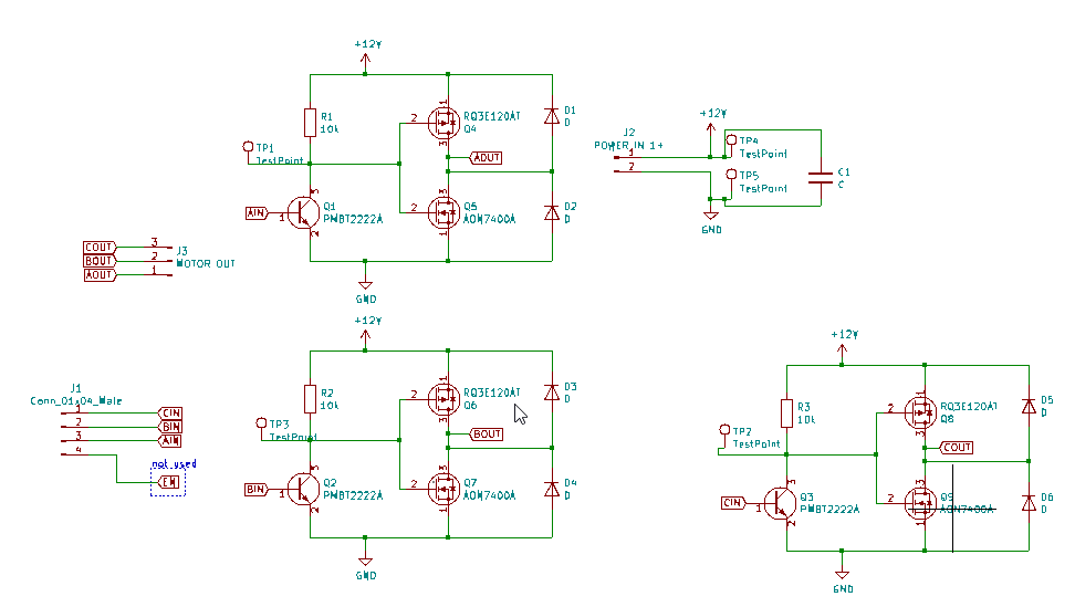
Figure 8-1 Discreet Motor PCB
PCB Layout (Discrete motor driver)
Because of the supply situation in the world, Oshpark was our primary source for PCBs. Because of this, it was in our best interest to make the footprint of the board as small as possible, whereas in the past JLCPCB’s $2 service would have limited us to 100mm^2. This caused us to design the driver board to be a 2 layer board that is as small as possible. This left us with a few choices of MOSFET. We wanted to choose MOSFETS more than capable of handling the current and switching speeds we needed, and we wanted the ability to add heatsinks to our design easily. We chose surface mount MOSFETs because that would allow us to use large, readily available (from e-waste) flat bottomed heatsinks. This also made it possible to shrink our design, as through-hole MOSFETS either need large (tall) heatsinks, increasing our enclosure’s minimum size, or need large amounts of board space to be laid flat. We chose surface mount BJT transistors for a similar reason, and SMD 1206 resistors were chosen for their ease of soldering. Once our components were chosen, we laid out where our inputs and outputs would be. It made the most sense for our logic inputs and power outputs to be 3 in a row, as there are 3 signals. Because of this, We laid out the power MOSFETS in 3 columns, one for each phase. This decision allowed us to create 3 large fill zones for the power to flow and the heat to dissipate. We laid the high side MOSFETs on one side of the board and the low side MOSFETs on the other side of the board. This decision allowed us to create 2 large power fill zones, allowing power and heat to flow easily. We then routed and placed the gate drives around the existing fills, as their power dissipation is extremely low.
IC Based PCB Design
Motor Driver (PCB)
Author/s:
Danny Jorquez (Power consumption and Motor Drivers)
Motor Driver
The motor driver PCB was designed using the DRV8313 IC chip. The DRV8313 uses 3 half H-bridges, sometimes called a triple H motor driver. The triple H circuit is designed to drive a 3 phase brushless DC motor (BLDC). For this project, we have a total of 3 BLDC’s, each requiring its own motor driver. The IC comes with 3 enable pins that can enable and disable each of the 3 half H-bridges. These must all be set to high at all times for our project. Setting them to high was done by connecting them to the 3.3V output pin of the DRV8313.
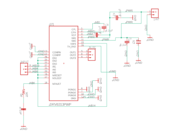
Figure 8-2. Motor Driver Schematic

Figure 8-2. Motor Driver PCB Layout
Mother Board (PCB)
Motherboard PCB
The motherboard was designed with an integrated inertial motion unit (IMU) called an MPU-6050. The IMU sends data to the Teensy 4.0 microcontroller which then sends the appropriate pulse-width modulation (PWM) to the BLDC’s which then move to the desired position. The motherboard takes in 18V from the solar team which it uses to drive the motor drivers. The teensy 4.0 and MPU-6050 run on 3.6V-5V so a buck converter was added to the PCB layout.
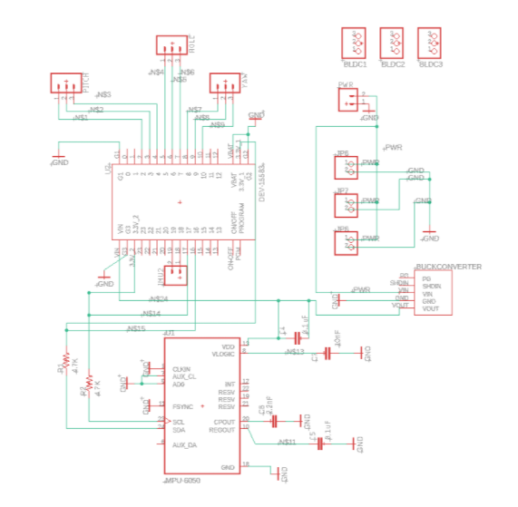
Figure 8-3. Schematic
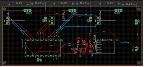
Figure 8-4. PCB Layout
Author/s:Gabriel Ayala (3D Modeling and Manufacturing)
Firmware
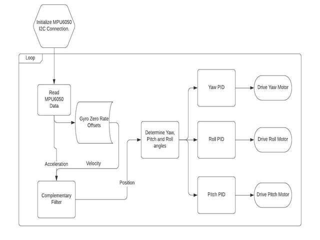
Figure 8-5 Firmware Flow Chart
Complementary Filter
- Get acceleration and velocity data.
- Second derivative of acceleration.
- First derivative of velocity.
- Take 95% of the gyroscope value and 5% of the accelerometer.
- Fuse data into position values.
Gyro Zero Rate Offsets
- Get raw gyroscope data.
- Subtract offsets determined in experimentation
- Output value.
Motor Drive Function
The SimpleFOC library is used to implement Field-Oriented-Control of the brushless DC motor. The library uses lookup tables to simulate a sinusoidal wave by varying the PWM duty cycle. It is intended for closed-loop control with encoders but only the motor output section of the library is being used. The motor control is configured as open-loop position control although feedback is being provided by the MPU6050.
Code for Motor Driver.
#define Vm 18 //supply voltage
#define Max_motor_V 8 // max voltage that can be supplied to motors.Sets duty cycle upper limit
#define Max_Velo 3 // [rad/s]sets maximum velocity for motors
#define pwmf 31000 //sets pwm frequency.
//initiates motor instances 14 pole pair for 12n14p configuration
BLDCMotor pitch_motor=BLDCMotor(14);
BLDCMotor roll_motor=BLDCMotor(14);
BLDCMotor yaw_motor=BLDCMotor(14);
BLDCDriver3PWM Pdriver = BLDCDriver3PWM(2,3,11);
BLDCDriver3PWM Rdriver = BLDCDriver3PWM(5,6,7);
BLDCDriver3PWM Ydriver = BLDCDriver3PWM(8,9,10);
//target position. will be implemented in main loop after control signal is calculated
float p_target_position=3;
float r_target_position=3;
float y_target_position=3;
int myEraser=7;
int myPrescaler=1;

void setup() {
  //driver config
  Pdriver.voltage_power_supply=Vm;
  Rdriver.voltage_power_supply=Vm;
  Ydriver.voltage_power_supply=Vm;
  Pdriver.init();
  Rdriver.init();
  Ydriver.init();
  pitch_motor.linkDriver(&Pdriver);
  roll_motor.linkDriver(&Rdriver);
  yaw_motor.linkDriver(&Ydriver);
  //limit motor movements
  pitch_motor.voltage_limit = Max_motor_V;
  roll_motor.voltage_limit = Max_motor_V;
  yaw_motor.voltage_limit = Max_motor_V;
  pitch_motor.velocity_limit = Max_Velo;
  roll_motor.velocity_limit = Max_Velo;
  yaw_motor.velocity_limit = Max_Velo;
  //pwm frequency
  //Pdriver.pwm_frequency=pwmf;
  //Rdriver.pwm_frequency=pwmf;
  //Ydriver.pwm_frequency=pwmf;
  /*config controller type.
  angle_openloop= open loop position control
  velocity_openloop= open loop velocity control
  */

  pitch_motor.controller = MotionControlType::velocity_openloop;
  roll_motor.controller = MotionControlType::velocity_openloop;
  yaw_motor.controller = MotionControlType::velocity_openloop;
  pitch_motor.init();//initiates motor hardware
  roll_motor.init();
  yaw_motor.init();
  TCCR1B &= ~myEraser;
  TCCR2B &= ~myEraser
  TCCR1B |= myPrescaler;
  TCCR2B |= myPrescaler;
  TCCR3B &= ~myEraser;
  TCCR4B &= ~myEraser;
  TCCR3B |= myPrescaler;
  TCCR4B |= myPrescaler;
}

void loop() {
  pitch_motor.move(p_target_position);
  roll_motor.move(r_target_position);
  yaw_motor.move(y_target_position);
}
Mechanical/Hardware Design
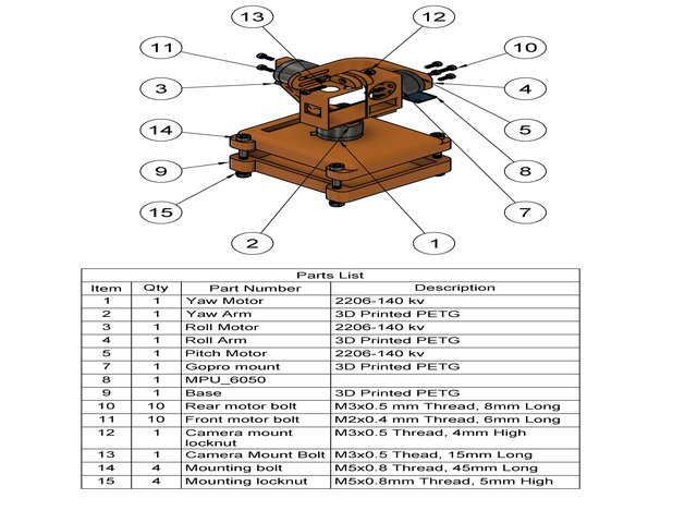
Figure 9-1 Exploded view of mechanical design with parts list.
The final design was modeled from scratch in Fusion360 and 3D printed out of PETG. The initial design was not used because of poor cable management and no adjustments for balancing the components. The final design uses slotted mounting holes to allow the camera and pitch motor to be counterbalanced, which reduces the torque requirements and increases system stability. The base (9) doubles as the electronics enclosure with mounts on the bottom section to secure the PCB and the top has 4 holes to attach the yaw motor(1). The M5 bolts (14) are used to attach the stabilizer to CommBot and hold the top and bottom of the base together. This method was chosen because other methods of attaching two 3D printed parts were not reliable or strong enough.


Author/s:Saqr Almuraikhi (Project Manager)
Verification & Validation Test Plan
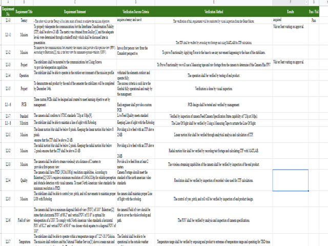
Figure 10-1 Verification Matrix
The verification and validation matrix Provides tests and methods on how we will check on the functionality of our end Product and make sure to provide a completed project by the day of the final.
Concluding Thoughts and Future Work
Going through this Project Taught us a lot about Group Work and organization having everyone on one page knowing each person’s progress and keeping in touch was key to making this project happen. since we all knew what each other are doing and knew how much progress we had done to each subsystem helped us a lot on pushing ourselves and not lack behind our peers. our project did not have a lot of moving parts so we worked more as a unit than engineers doing their parts and that’s it we helped each other whenever we could and that made the project feels easier.
References/Resources
1-PDR.
3-Verification and validation plan.
5-Fritzing Files.
7-Arduino Code (Motor Driver) (IMU).
8- V1 Gimbal simulation and ITF Files/
9- Final Video
Citation
[1] Guilluy, W., Azeddine Beghdadi, & Oudre, L. (n.d.). A performance evaluation framework for video stabilizations methods . laurentoudre. Retrieved September 30, 2021, from http://laurentoudre.fr/publis/GBO-EUVIP-18.pdf.
[2] Balestrieri, E.; Daponte, P.; De Vito, L.; Lamonaca, F. Sensors and Measurements for Unmanned Systems: An Overview. Sensors 2021, 21, 1518. https://doi.org/10.3390/s21041518
[3] https://www.weather.gov/wrh/Climate?wfo=lox
[4] https://www.thingiverse.com/thing:1247236
[5] Freeman, W. J. (2013, April 26). Digital Video Stabilization with Inertial Fusion. Vtechworks. https://vtechworks.lib.vt.edu/bitstream/handle/10919/23080/Freeman_WJ_T_2013.pdf?sequence=1
[6]Souza, M. R., & Pedrini, H. (2018). Digital Video Stabilization Based on Adaptive Camera Trajectory Smoothing. EURASIP. http://www.diva-portal.org/smash/get/diva2:831423/FULLTEXT01.pdf
[7] https://wallpapershome.com/hi-tech/robots/robot-dog-spot-boston-dynamics-22636.html
[8]https://www.cnckitchen.com/blog/comparing-pla-petg-amp-asa-feat-prusament
[9] https://learn.adafruit.com/adafruit-sensorlab-gyroscope-calibration?view=all
[10] https://youtu.be/_ec6FOYAvKk
[11] https://howtomechatronics.com/tutorials/arduino/arduino-and-mpu6050-accelerometer-and-gyroscope-tutorial/