
Inductive Sensor Issues and Fix – Ugly Blues
Introduction:
Inductive sensors can be tricky. For this project, we used the LDC 1612 inductive sensor. This is a 10-bit, 2 channel, inductive sensor that runs over I2C. For testing, I used the SEEED Studio “Grove – 2 Channel Inductive Sensor”. This sensor incorporates the LDC1612 and even comes with an accompanying library file that works with the 3dot. All testing worked flawlessly with this breakout board. However, trouble came during the manufacturing of our PCBs. There were 2 main problems, the library no longer worked and when I tested with a different “working” library, the values the LDC sensor gave seemed to be random. Both of these issues I was able to fix are described below.
Coil design is an Art:
It turns out my coils were not identical to the Groove sensor. I had to use a thicker trace value for Oshpark to be able to create my PCB and by doing so, I changed the characteristics of the coil. To design the coil I used TI’s coil designer which can make compatible coils for the LDC sensor(it is a TI sensor). This wasn’t the problem, the problem was the capacitor in parallel with the coil. The groove sensor used a 100pF capacitor and with my coil the values given by the sensor were unstable. So with a lot of testing, I found a suitable value of 47pF. Keep this in mind if you want to use this sensor, try to make it exactly the same as the Groove sensor to minimize any problems with the coils.
https://webench.ti.com/wb5/LDC/#/spirals
https://www.ti.com/lit/an/snoa930b/snoa930b.pdf?ts=1620945473204&ref_url=https%253A%252F%252Fwww.google.com%252F
LDC1612 Libraries:
So my sensor would not communicate with the Groove sensor library. After a long time searching I found another library written by a physics professor to test inductors for his class. This library did work but it was very “bare-bones” and did not have a dual-channel mode, something I needed. The reason my front shield did not work was because I used the internal cyrstal oscillator of the LDC sensor while the groove breakoutboard used a physical component added to the board. Since this device was I2C. I need to initialize it to use the internal crystal instead. The fix can be seen here:
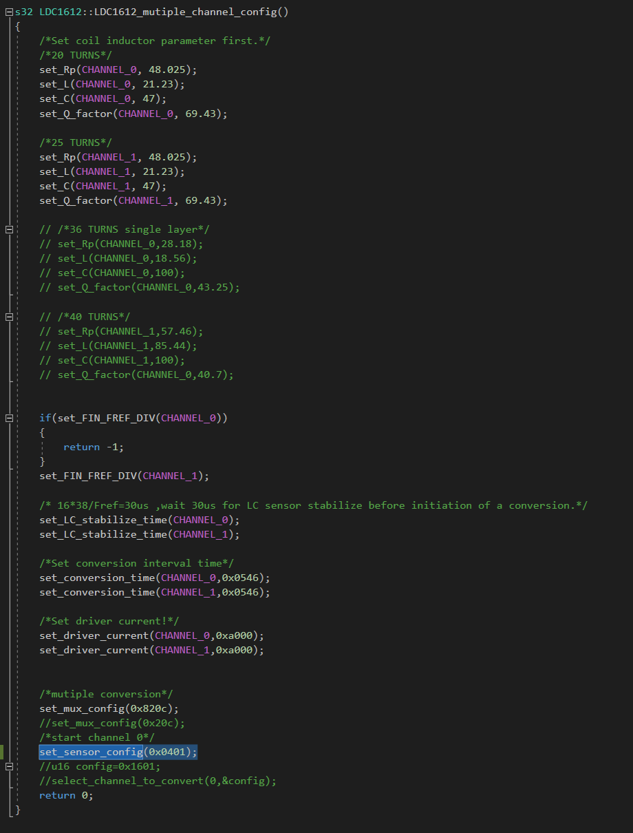
This code is in the “Seeed_LDC1612.cpp” in the Arduino library under the Multichannel config function. By changing the highlighted value to 0x0401 from 0x1601 the internal oscillator will be running the chip. This coincides with the part of the LDC datasheet:
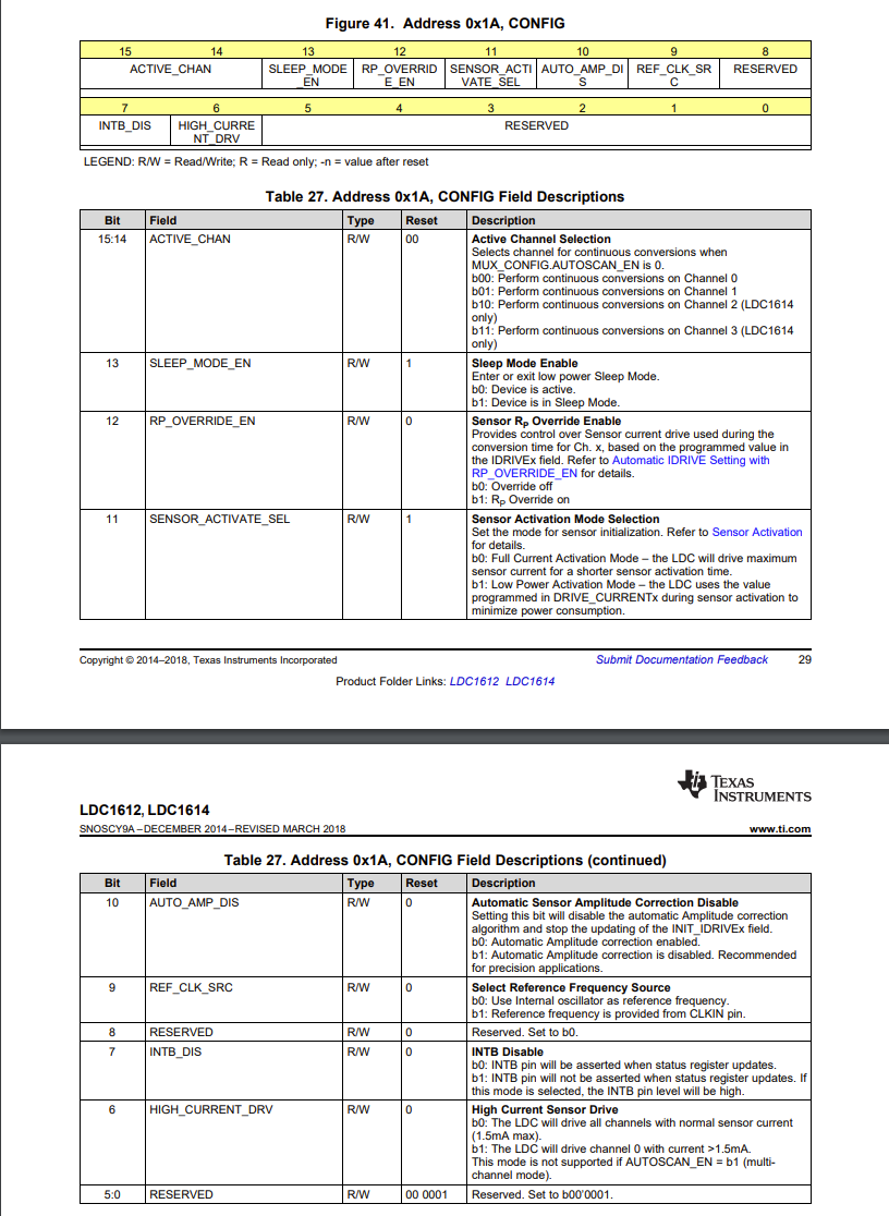
We are changing bit 9 from 1 to 0 which enables the internal oscillator. I also changed bit 12 from 1 to 0 which gave me more consistent readings. I hope this helps someone!