MicroSpot Generation Two
Author/s: Dino Asmar, Joseph Hartman, Domingo Sainz
Verification: Gary Hill & Christopher Hirunthanakorn
Approval:
Table of Contents
Executive Summary
Author: Dino Asmar
Let me introduce you to the future. Dreaming about a dog that can follow its target? Here is the solution. Microspot is the scaled-down of the Boston Dynamic quadruped. A robot god that is fun to walk with and take him with you on your daily morning walking. Microspot is a quadruped that walks safely. Microspot is going to receive Bluetooth signals and data using either android and iPhone Arxterra or RoboPilot app.
Program and Project Objectives
Author: Dino Asmar
To build a down-scaled quadruped robot dog similar to the Boston Dynamics Robot Dog. The MicroSpot robot dog will utilize micro servos to support the motion of the robot dog. Moreover, each student must design a custom printed circuit board (PCB) in order to support the functionality of the MicroSpot robot dog. Also, the robot dog will be powered by a 3DoT board and controlled by the ArxRobot App.
Mission Profile
Author: Dino Asmar
The MicroSpot Robot Dog will walk through the Earl Burns Miller Japanese Garden path located at California State University, Long Beach on December 14th, 2021 at 7:15 pm-9:15 pm, without disturbing any sacred elements of the Japanese Garden. The path is 138 meters in distance and it is composed of different sections, such as wood, marble, cement, and inclines. Many functions such as moving forward, backward, left, and right going to take place in order for Microspot to complete the path.
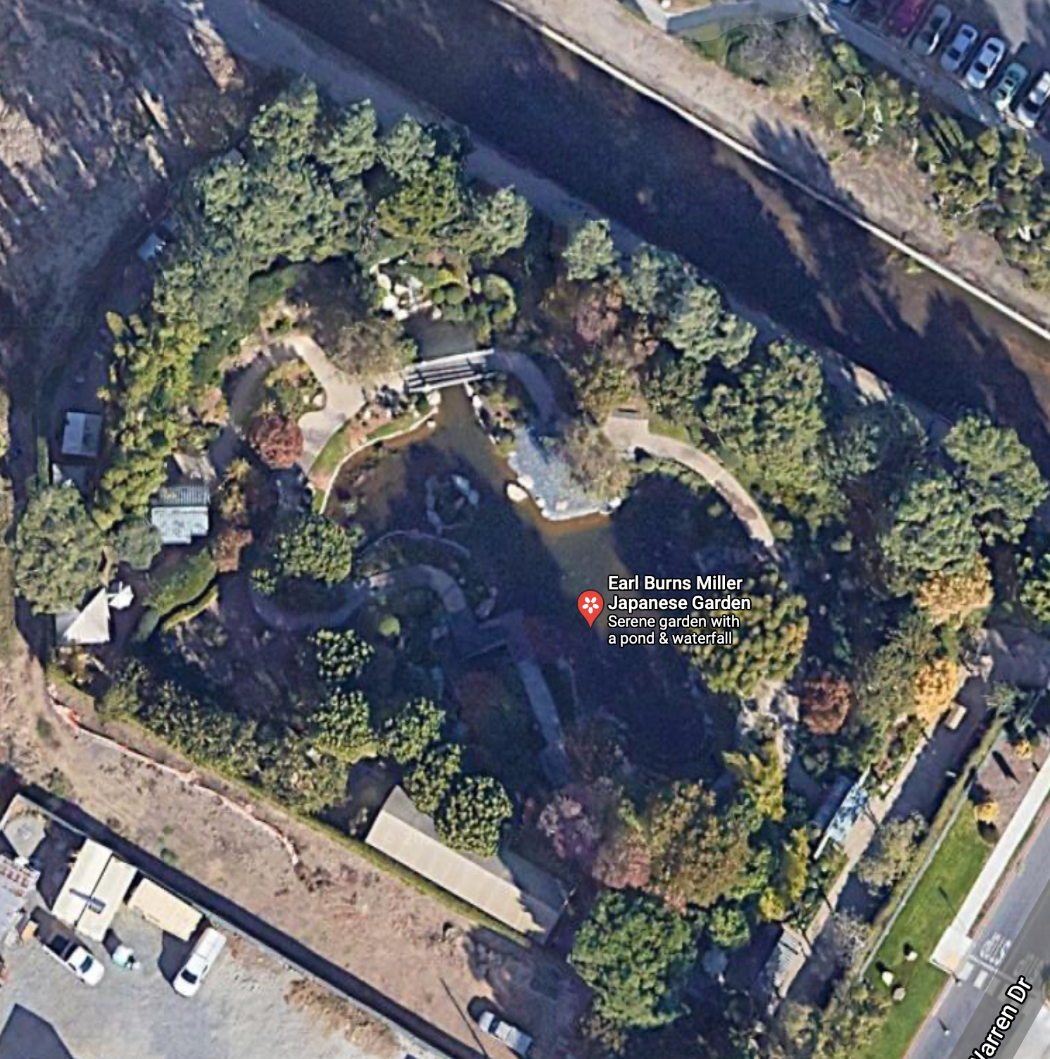
Figure(1). Japanese Garden Path
Project Features
Author/s: Dino Asmar, Joseph Hartman, Domingo Sainz
Verification: Dino Asmar
Approval: Dino Asmar
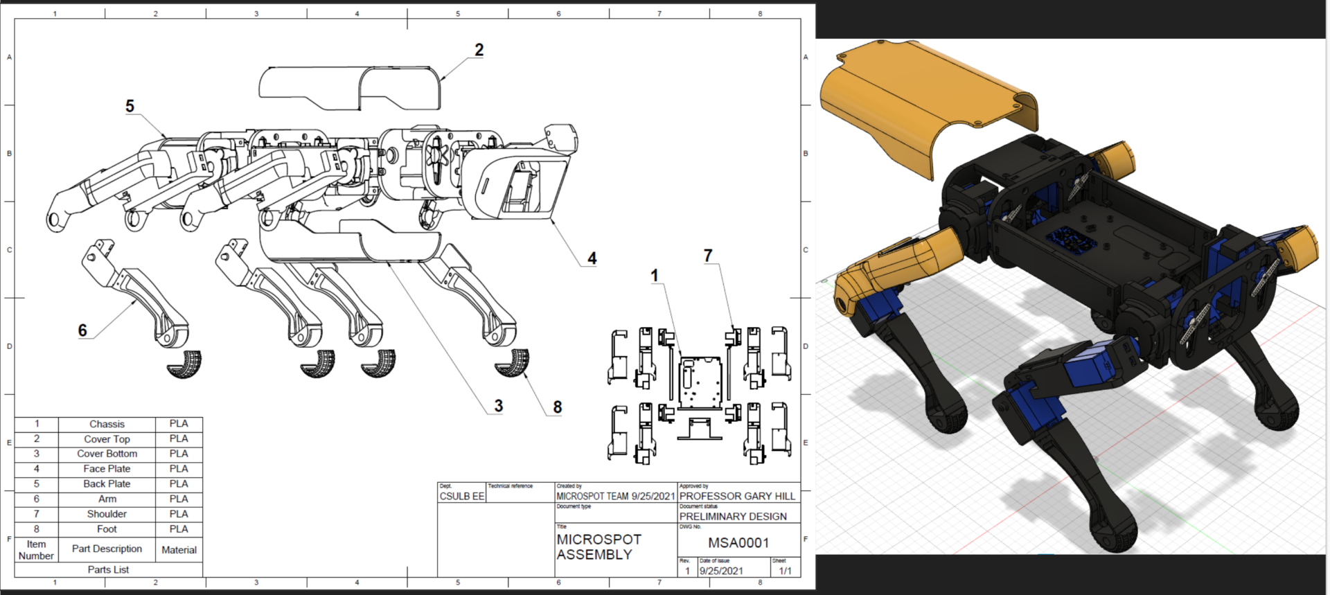
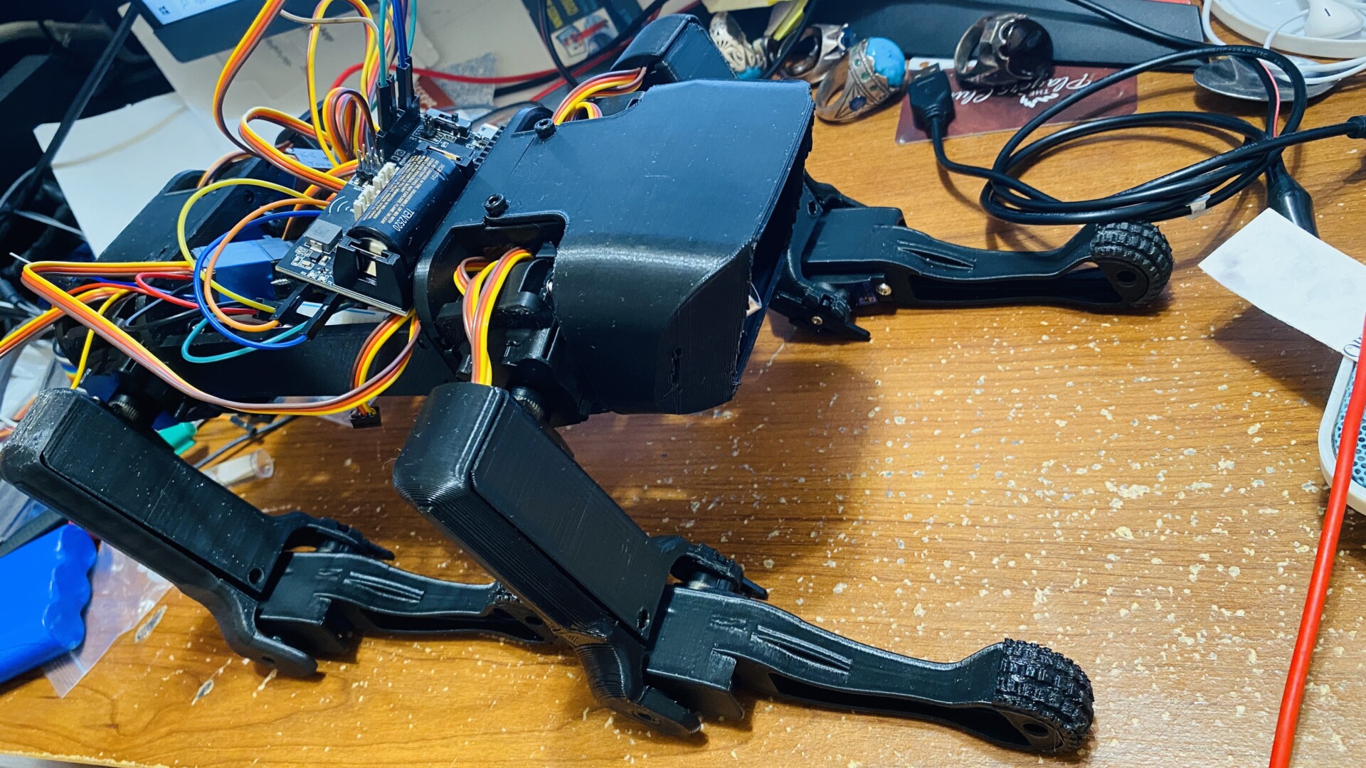
3D Model is a scaled-down of the Nova Spotmicro and it was designed and modeled to be able to be compatible with micro servos MG92B. Fusion 360 was used to 3D model the Microspot’s model.

Figure (2). 3D Model
The system block diagram is like the schematic showing what is connected together except it’s simplified. When making a schematic I think this may be the best way to start. Getting a general idea of what is needed then using this to connect actual components virtually with a fritzing app for a more detailed view. The arrows show the direction of the signal like for example the servos just receive while the ultrasonic sensor not only receives but also sends to the 3dot board. The color isn’t needed for this simple diagram but for larger diagrams color might help group things together into a category that can later be used for the product breakdown structure or for the work breakdown structure. A printed circuit board is where twelve servos get their commands.
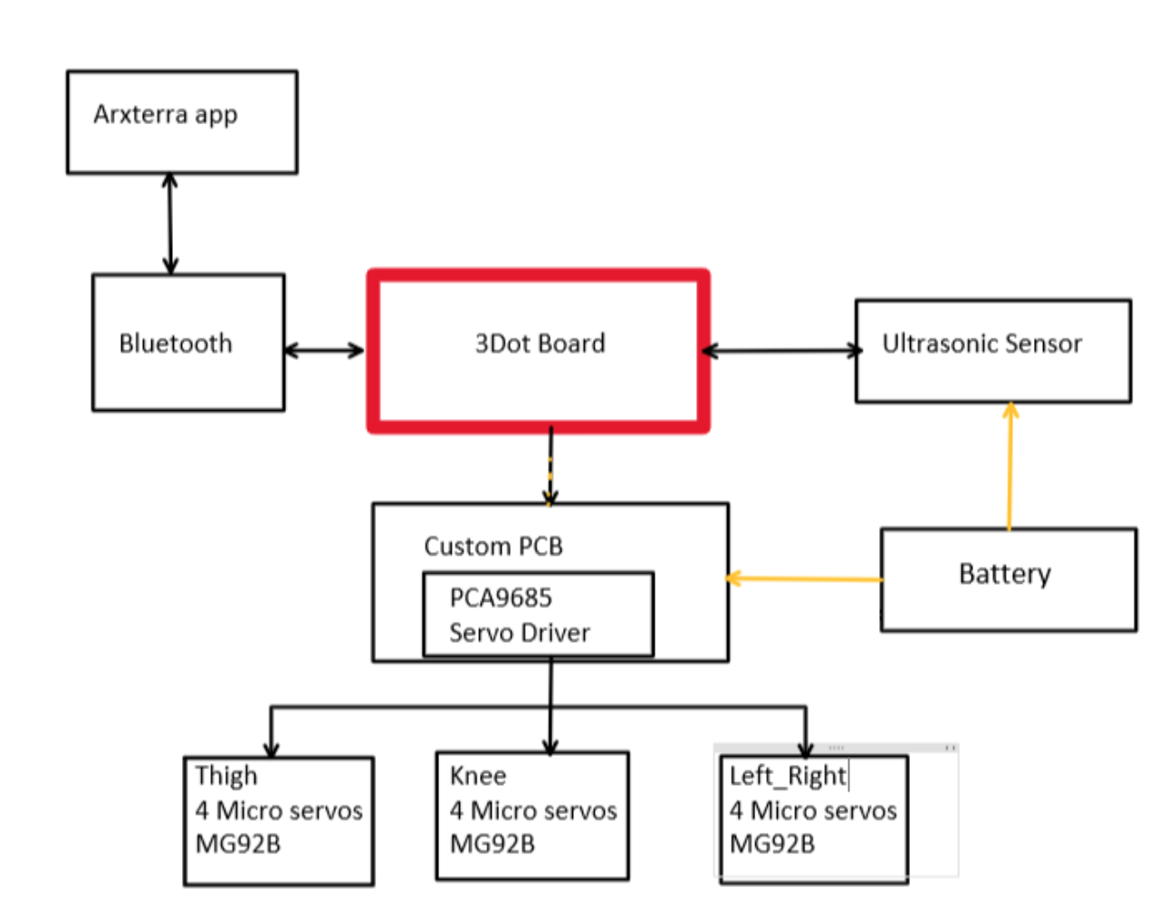
Figure(3). System Block Diagram
Microspot uses three micro servos per leg, which is a total of twelve servos that Microspot uses. Microspot uses those twelve servos to move left and right, back and forward. In addition, the brain of the Microspot is 3Dot Board that features the Bluetooth module.
Requirements
Engineering Standards and Constraints
Author: Dino Asmar
Microspot shall be constrained to a Cost not to exceed $900.
Microspot Schedules shall be constrained to a completion date of Tuesday, December 14, 2021. Project completion includes documentation and materials purchased by or loaned to the project.
Usability of Microspot shall be enhanced use of the Arxterra phone and control panel application as dictated by the assigned mission.
Constructability of Microspot shall be documented at the CDR and approved by the president of the robot company. Constraints imposed by this requirement include the use of bushing or bearings in all moving and rotating parts. Interlocking Hinges with a latching mechanism.
Manufacturability of Microspot shall utilize as few files as possible when 3D Printing the Robot and its parts.
The Size of the electronics enclosure shall be constrained to be no greater than the 3DoT board, 3DoT shield(s), and associated mounting hardware.
Power to Microspot shall be provided by the 3.7V RCR123A battery included with the 3DoT board or use of the external battery 2.0mm PH series JST connector located on the 3DoT board. The RCR123A is a Lithium Polymer LiPo battery. All Safety regulations as defined in Section 4.3 Hazards and Failure Analysis of this document shall apply to the shipping, handling, storage, and disposal of LiPo batteries.
Power to Microspot shall be provided by the 3.7V 750 mA 2.775Wh Li-Ion battery included with the 3DoT board or use of the external battery 2.0mm PH series JST connector located on the 3DoT board. Compliance will be provided in Section 3.5 Power in the Final Blog Post. Measured current shall have a margin of 5%. Contingency shall be based on measured current, plus margins associated with each line item, minus 750 mA with an assumed depth of discharge of 80% grams (i.e., 600 mA).
Back of the envelope calculations and experiments shall be conducted to set the diameter of Power carrying wires. Follow the American Wire Gauge (AWG) standard when defining the diameter of power-carrying wires. This work is to be completed and documented by the CDR.
Robot Interoperability
Microspot shall incorporate the 3DoT v9.05 or later series of boards.
Software shall be written in the Arduino De facto Standard scripting language and/or using the GCC C++ programming language, which is implements the ISO C++ standard (ISO/IEC 14882:1998) published in 1998, and the 2011 and 2014 revisions. Required exceptions to this standard can be found here.
Microspot shall be in compliance with the 3DoT Command and Telemetry Packet specification.
Microspot shall be controlled via Bluetooth 4.0 in compliance with the Bluetooth Special Interest Group (SIG) Standard (supersedes IEEE 802.15.1).
Applicable Engineering Standards
- Microspot shall comply with IEEE 29148-2018 – ISO/IEC/IEEE Approved Draft International Standard – Systems and Software Engineering — Life Cycle Processes –Requirements Engineering.
- Microspot shall comply with NASA/SP-2007-6105 Rev1 – Systems Engineering Handbook
- Microspot shall comply with Bluetooth Special Interest Group (SIG) Standard (supersedes IEEE 802.15.1)
- Microspot shall comply with C++ standard (ISO/IEC 14882:1998)
- Microspot shall comply with Federal Communications Commission (FCC) Relevant standards for a product implementing a 2.4GHz radio, FCC Intentional Radiators (Radio) Part 15C, and Unintentional Radiators FCC Part 15B for CPU, memories, etc.
- Microspot shall comply with NXP Semiconductor, UM10204, I2C-bus specification, and user manual.
- Microspot shall comply with ATmega16U4/ATmega32U4, 8-bit Microcontroller with 16/32K bytes of ISP Flash and USB Controller datasheet section datasheet, Section 18, USART.
- Microspot shall comply with USB 2.0 Specification released on April 27, 2000, usb_20_20180904.zip
Environmental, Health, and Safety (EH&S) Standards
- Microspot shall comply with CSULB COE Lab Safety
- Microspot shall comply with CSULB Environmental Health & Safety
- Microspot shall comply with IEEE National Electrical Safety Code
- Microspot shall comply with NCEES Fundamental Handbook
- Microspot shall comply with ASTM F963-17, compliant for Toy Safety
Program Level 1 Requirements
Author: Dino Asmar
L1.1 MicroSpot shall travel the path (138 meters) through the Earl Burns Miller Japanese Garden in order to complete the Mission Profile. This will be verified by having the MicroSpot Robot Dog start the path at the entrance of the Japanese garden and end back at the same spot.
L1.2 MicroSpot shall walk forwards, backward, and sideways utilizing micro servos in order to complete the path stated in the Program Objectives. This will be verified by having the robot walk forwards, backward 10 steps as well as turn left and right about 90 degrees.
L1.3 MicroSpot shall utilize remote control and telepresence to get through the path without disturbing any sacred elements of the Japanese Garden as stated in the Mission Profile.
L1.4 MicroSpot should implement dynamic walking in order to increase the speed of the robot dog and complete the Japanese garden path within the designated time as stated in the Mission Profile. This will be verified by observing the robot dog’s motion, where opposite legs must be walking simultaneously, which should theoretically increase the speed by half when compared to sequential walking.
L1.5 MicroSpot will be powered by a rechargeable battery built-in to the 3DoT board as defined in the Program Objectives.
L1.6 Robot’s size shall be no larger than 25% of the dimensions of the Boston in inches (10.82 x 4.93 x 6.9) as per the limitations of the 3DoT board and the micro servos as stated in the Program Objectives. This will be verified by measuring the size of the chassis and legs (length, width, and height) whilst the robot is in a static and standing position and compare to the size of the 3DoT board along with the micro servos.
L1.7 Robot shall use a custom-built and designed PCB from each student in order to connect components and have the project functional by the final date (December 14th) as stated in the Program Objectives. Verification will be performed with the connection of the 3DoT board to the custom PCB board and testing the assembly to make sure that the 3DoT interfaces properly with the elements in the PCB board.
L1.8 Robot shall cost no more than $900 as verified in cost analysis as it will be funded by the department. Verification will be demonstrated through the power report or cost analysis.
L1.9 Robot shall be functional by December 14, 2021, as defined by the course outline and validated at 2:45 pm as stated in the Mission Profile. Verification will be done with the demonstration of the robot’s functionality on the day of the final.
L1.10 MicroSpot shall have the proper material in order to have enough traction for the robot dog to be able to walk on inclines and declines as well as through all other sections of the path as stated in the Mission Profile. Verification will be done by having the robot dog go up and down the wooden bridge at the Japanese garden.
System/Subsystem/Specifications Level 2 Requirements
Author/s: Domingo Sainz
Verification: Dino Asmar
Approval: Dino Asmar
L 2-1 -An external 5v power source will be used to power the 12 micro servos and ultrasonic sensors.
L 2-2- A servo driver will be used to help the 3Dot control all 12 servos.
L 2-3 -The user shall be able to control the Microspot’s motions by selecting the relevant option in the app
L 2-4 -MicroSpot’s body parts will be 3d printed with PLA for its durability and low cost.
L 2-5- Microspot will not have wires or electronics sticking out except for the sensors.
L 2-6 -Each leg shall use 3 micro servos in order to be able to move in all directions.
L 2-7 -Microspot shall use ultrasonic sensors to avoid crashing into obstacles by turning in left or right.
L 2-8 -Microspot shall walk uphill on a slope of 2%.
L 2-9 -Microspot shall walk downhill on a slope of 2%.
L 2-10- micro servos will have a torque higher than 3 kg.cm. In order to move the legs
L 2-11 -The custom PCBs should fit in the MicroSpot chassis.
L 2-12 -The custom PCBs should be designed using Eagle CAD.
L 2-13 -MicroSpot shall be able to move all 4 of its legs by the due date of December 15 ,2021.
L 2-14 -MicroSpot shall be able to walk without falling over.
L 2-15 -Terminal blocks should be used instead of splices if needed during wire installation to help prevent any wires from coming loose during MicroSpot’s walking movement.
Allocated Requirements / System Resource Reports
Author/s: Dino Asmar, Domingo Sainz, Joseph Hartman
Verification: Dino Asmar
Approval: Dino Asmar
Back-of-the-Envelope Calculation – Torque Calculation
The torque equation is used to find out if the torque of the motor at each joint location is enough to move the joint based on the load that the joint will need to experience. The equation takes into account the total weight, the weight on each leg, gravity, the length of the different parts of the legs, the stall torque of the MG92B servo, and the angle of the leg joints.
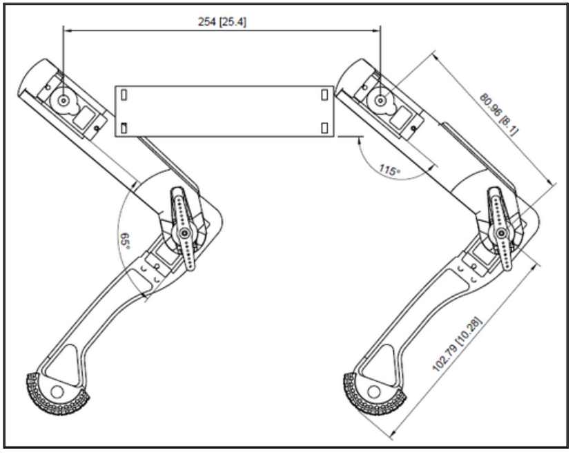
Figure(4). Torque calc
Battery Life Calculation
We are using an 8000 mAh battery to power our MicroSpot. The battery will supply power to the 12 micro servos (780 mA each), power boost (18.9mA), servo driver (25mA), ultrasonic sensor (15mA), and 3DoT board (20mA). In the equation, I added all of the load currents and then divided it by the battery capacity in order to find the duration the battery will last before draining completely.
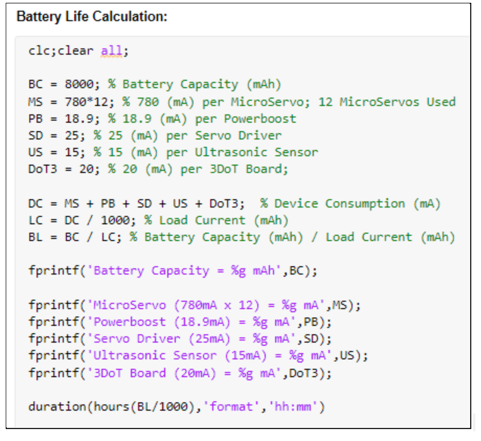
Figure(5). Battery Life Calculation
Battery Life Results
Based on the calculation, the 8000 mAh battery will supply power to the 12 micro servos (780 mA each), power boost (18.9mA), servo driver (25mA), ultrasonic sensor (15mA), and 3DoT board (20mA) for a duration of 50 minutes at full power. This is a model of how the power will work but most likely the duration will vary based on the actual battery capacity, which may be less than stated and based on which components are drawing full power at different durations of time. All values are based on the actual current that we measured from each component.
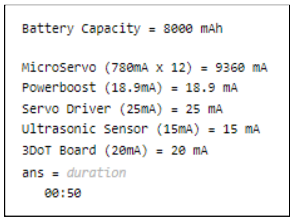
Figure(6). Battery Life Results
Author/s: Joseph Hartman
Verification: Dino Asmar
Approval: Dino Asmar
Mass in the Final Blog Post. Measured mass shall have a margin of 2%. Contingency shall be based on measured mass, plus margins associated with each line item, minus 1295 grams.
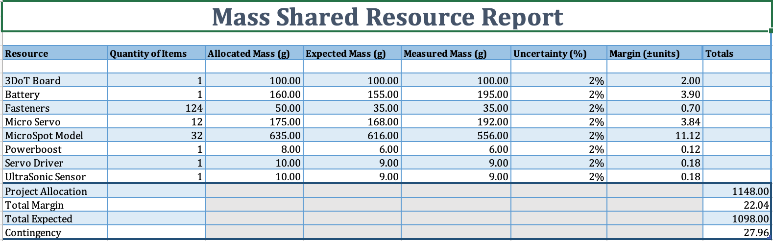
Figure(7). Mass Shared Resource Report
Author/s: Joseph Hartman
Verification: Dino Asmar
Approval: Dino Asmar
Level X Requirement: A 3.7V Li-Ion battery will provide power to the MicroSpot components with an estimated capacity of 8000 mAh, a power rating of 5A and 29.6Wh. The external battery will attach to the power boost by using a JST PH series 2.0mm connector spliced onto the attached battery wires to power the servo driver, micro servos, ultrasonic sensor, and 3DoT board.
Compliance will be provided in Section x Power in the Final Blog Post. Measured current shall have a margin of 5%. Contingency shall be based on measured current, plus margins associated with each line item (e.g., datasheet), minus 12040mA.
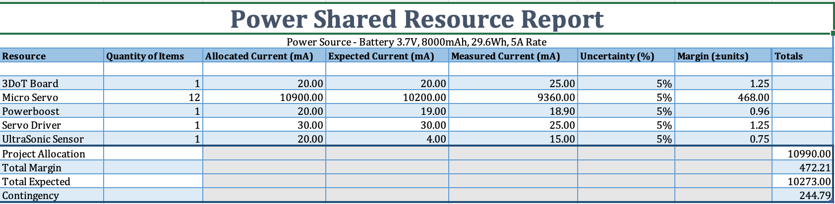
Figure(8). Power Shared Resource Report
Project Report
Author: Dino Asmar
Project WBS and PBS
Author: Dino Asmar
Project Work Breakdown Structure (WBS) and Product Breakdown Structure (PBS)
Project Work Breakdown Structure (WBS):
Microspot mainly was divided into 3 major categories including MST, Electronics and Controls, and Manufacturing Division. Each of the categories is divided into different subcategories. Some of the assigned tasks were designed to be done by one individual. In addition, some tasks overlap and needed to have two team members collapse and finish the assigned task.
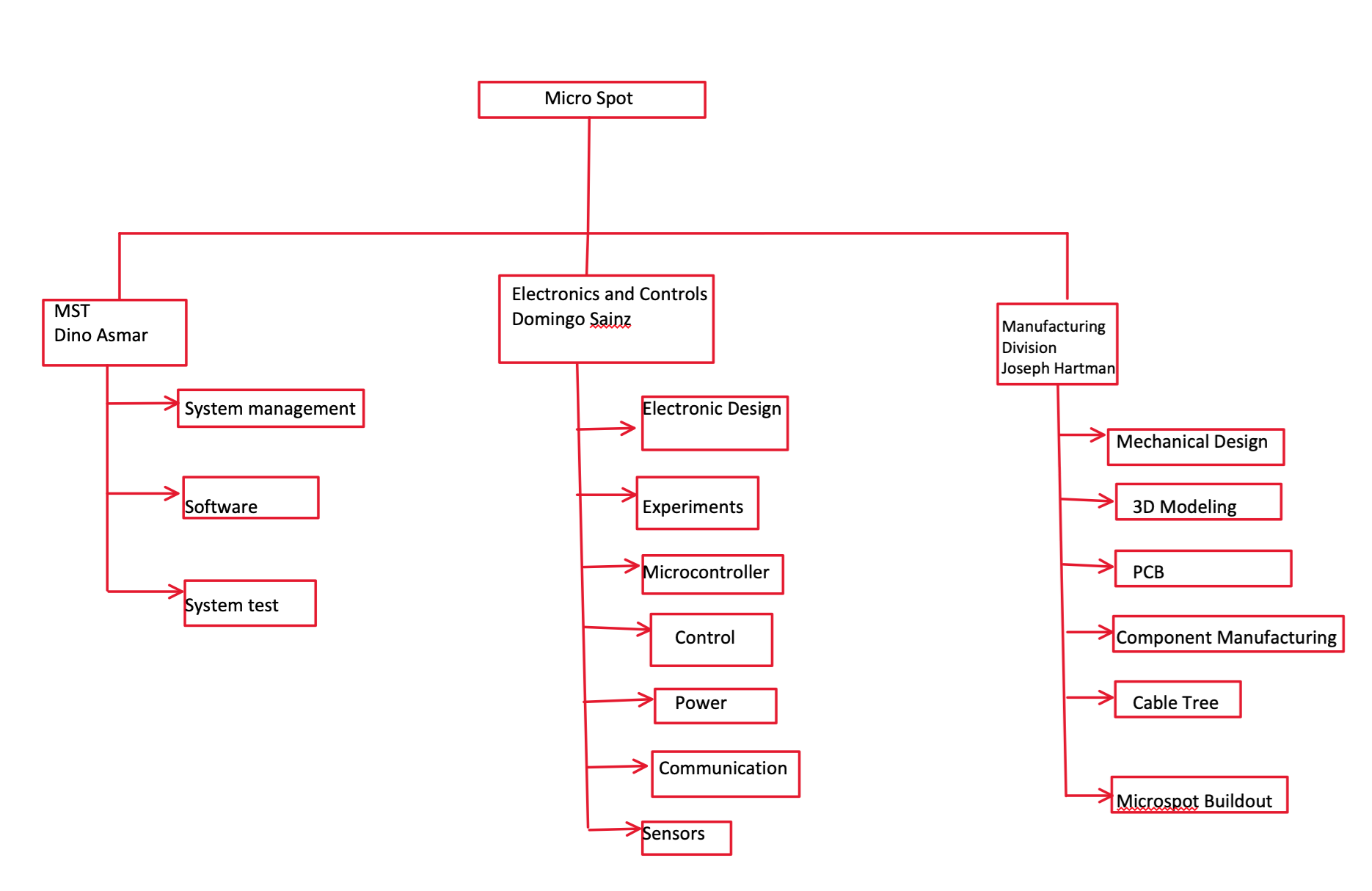
Figure (9). Work Breakdown Structure
This diagram is the Product Breakdown structure which helps show the main parts for the microspot we are making. Each major part is being done by certain group members. These major parts are called Power, Production, Sensors, and Software. Under Power, battery and power booster is included showing what will be used to provide power to the robot. In Production, the words chassis, legs, face cover, and custom PCB are included and will cover anything that needs to be produced that will provide structure to the robot. The next is sensors which cover the ultrasonic sensors that will allow the robot to avoid a collision. The final is software and under it has arxterra app, Bluetooth, and 3dot.
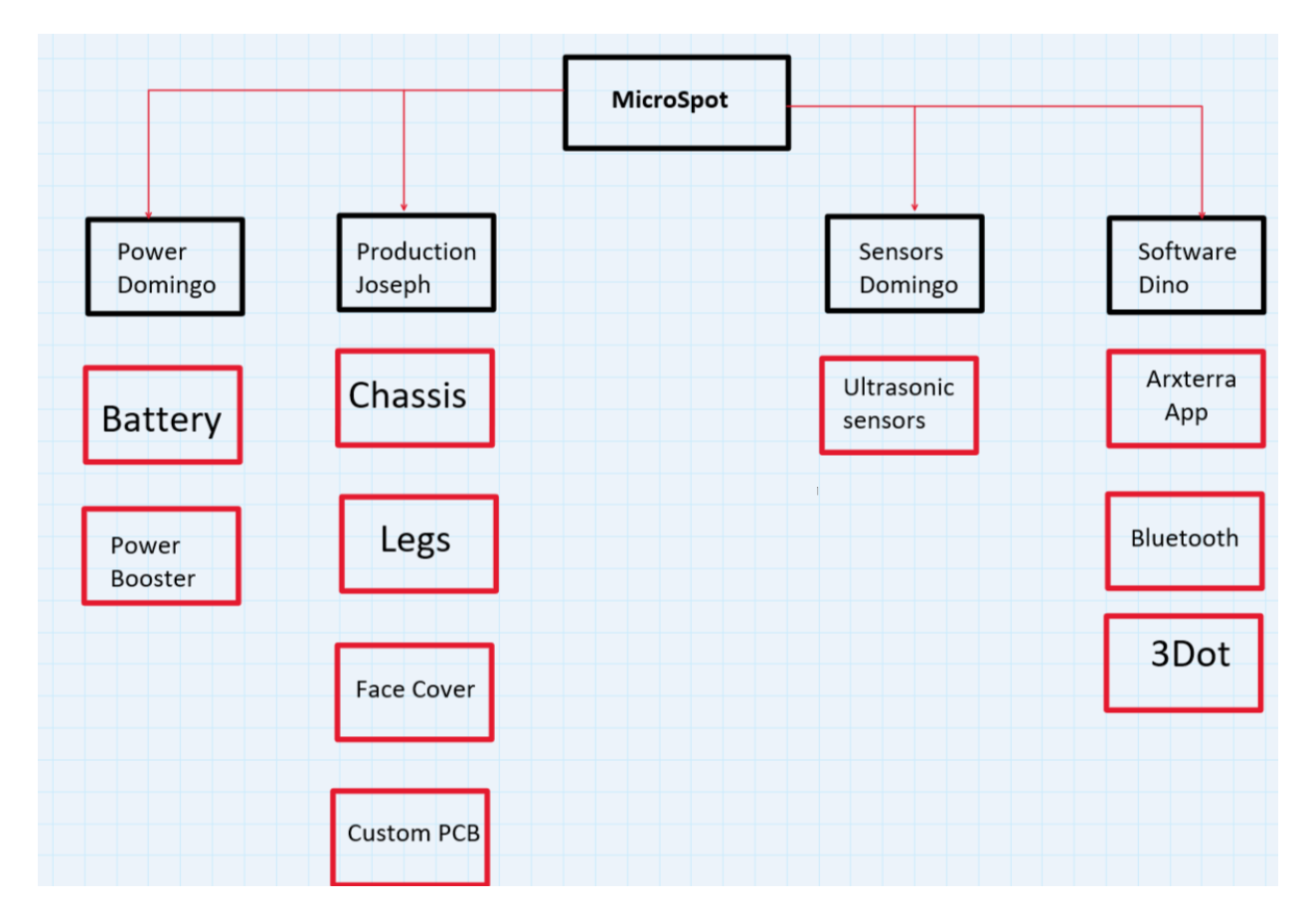
Figure (10). Product Breakdown Structure
Cost
Author: Dino Asmar
The cost for the Microspot breakdown below:
Here is the file to access for the future students
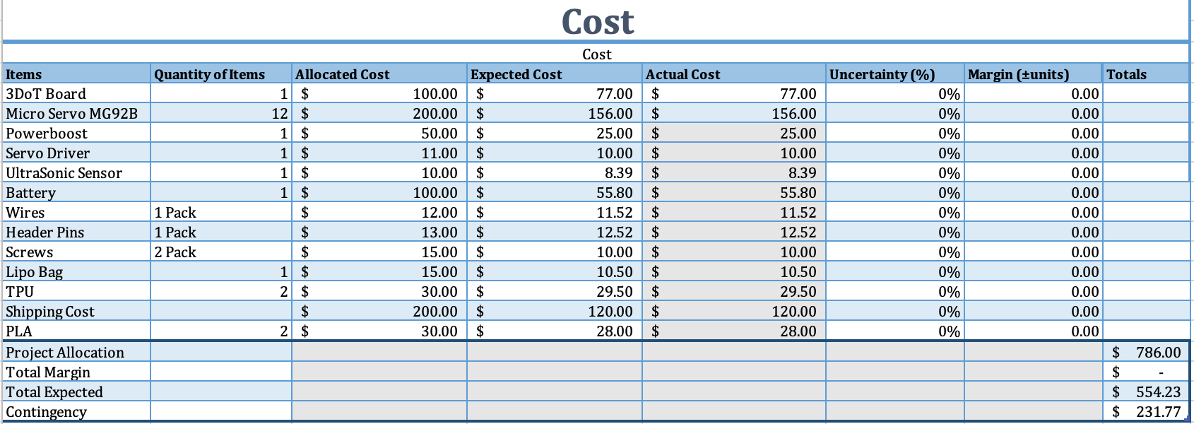
Figure(11). Cost Breakdown of the Microspot
Schedule
Author: Dino Asmar
Here is an updated schedule, generated through programs like ProjectLibre or Microsoft Project, showing the system and subsystem tasks that have been completed or are still in progress
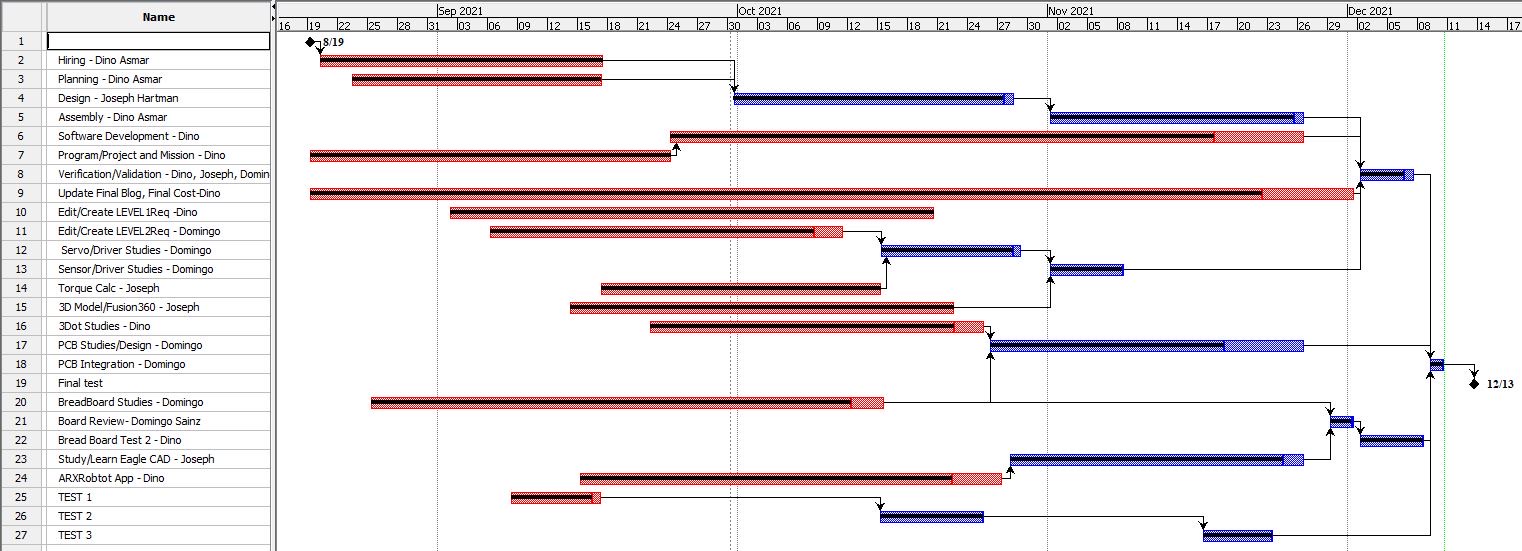
Figure(12)Schedule
Concept and Preliminary Design
Literature Review
Author/s: Dino Asmar, Joseph Harman
Verification: Dino Asmar
Approval: Dino Asmar
Before starting on anything, research was done and looked up as many robot dogs as possible. Afterward, they are put together in a google sheet with specific information labeling each row. Each robot’s information is then added to each row. Then a new column is added for requirements and we use it to find out if the robot meets the needs we have for our robot. This spreadsheet was constantly updated with a new robot over the semester. A software section of requirements was later added too.
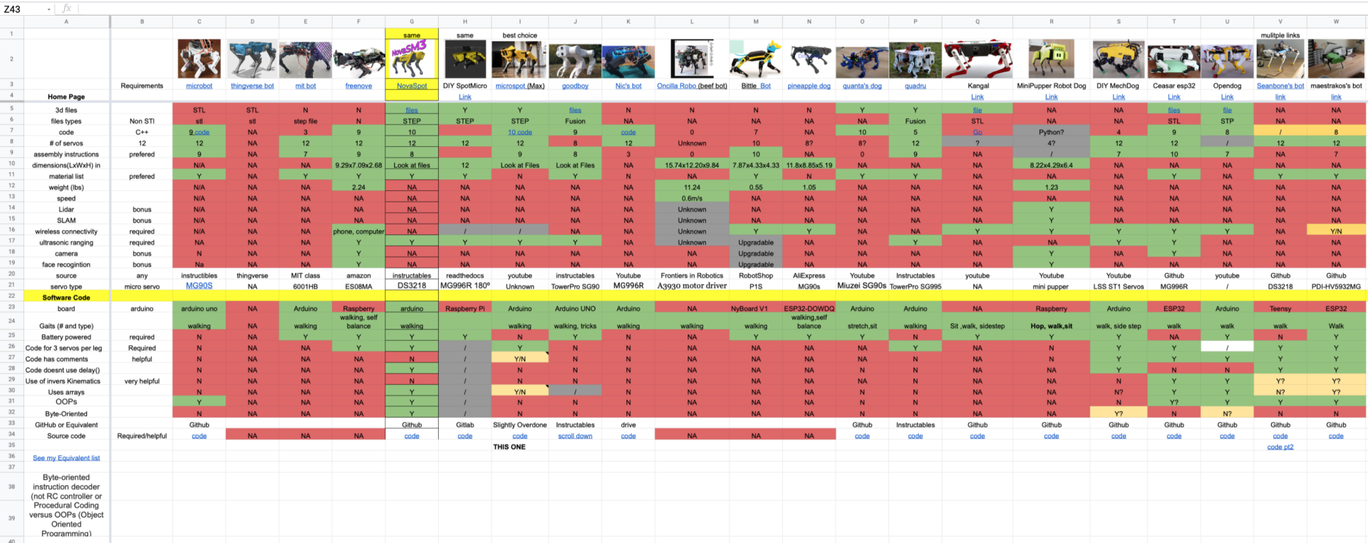
Figure(13). Specifications Table
In the beginning, the Microspot was designed to walk on 8 micro servos, then after trade-off studies and more research on the walking pattern. The design team and PM decided to use 12 micro servos in order to provide more stability and a better walking pattern. Using 12 micro servos on Microspot can provide better turn to the left and right directions and more smooth walking when operating the Microspot
Figure(14). MicroSpot using 12 servos idea
Design Innovation
Author/s: Dino Asmar, Joseph Hartman, Domingo Sainz
Verification: Dino Asmar
Approval: Dino Asmar
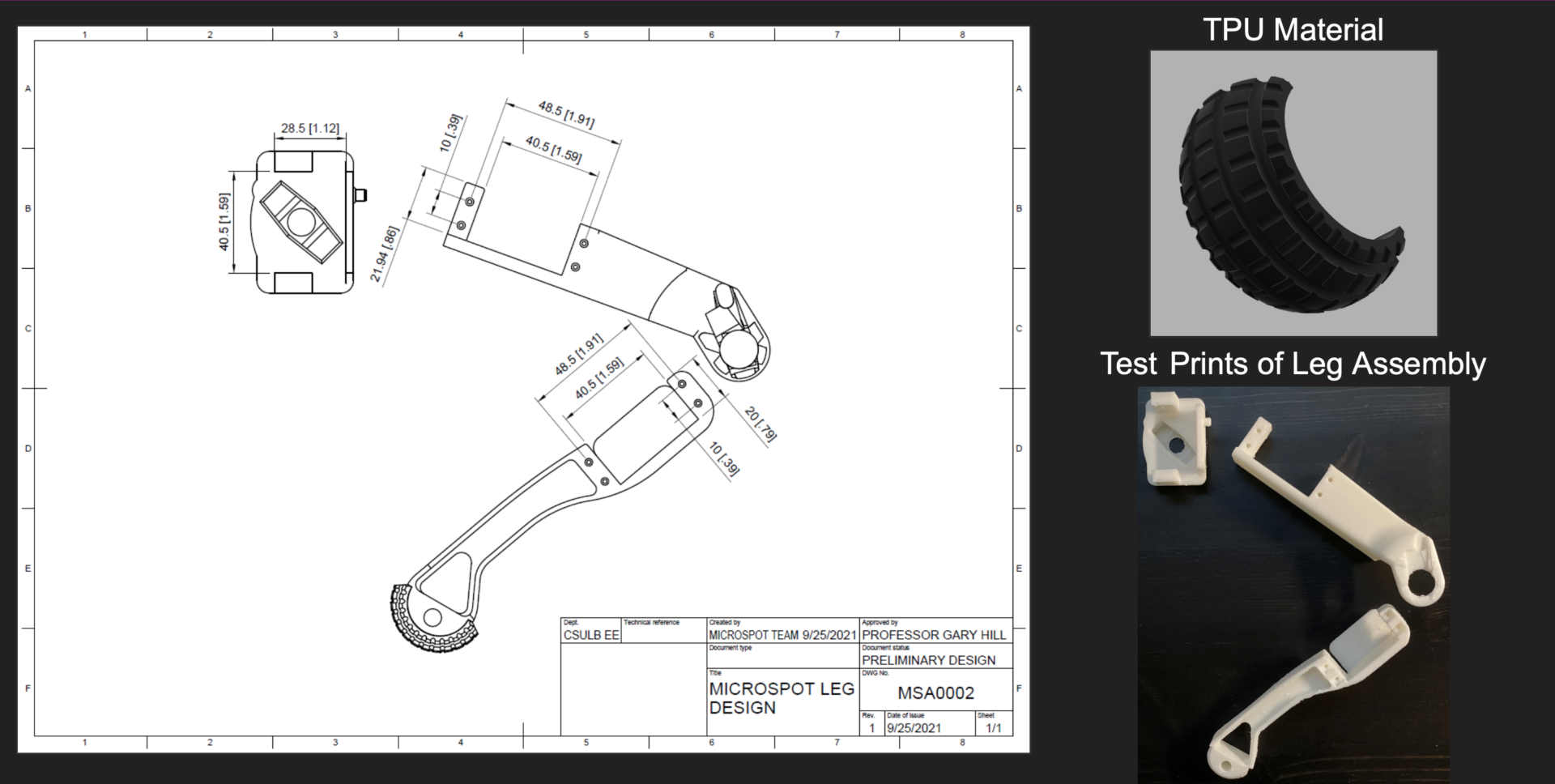
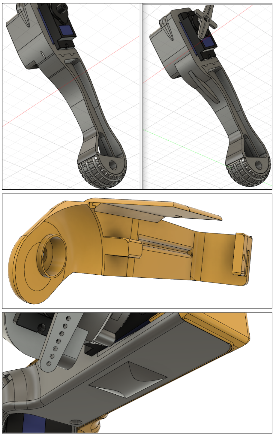
The original SpotMicro foot, when printed, did not fit on the printed leg because the foot cutout that mounts onto the leg was not the correct size. To fix this, I modified the inner walls of the inside of the foot in the model and reprinted the foot in order to make sure that the foot fits on the leg correctly.
The original SpotMicro foot did not have much tread to grip a surface, similar to a bald tire. I modified the foot model in order to give the foot more tread similar to a new tire in hopes that the foot will grip the concrete and other floor materials better, hopefully allowing for a more efficient time when walking around the Japanese Garden.
Figure(15). Using 3 servos
We built a physical model in order to test the joint movements of the different leg parts. We needed to test the interference when the motor would operate and how much of an angle is available for movement of the leg before the leg piece would hit another part during movement.
Figure(16). Physical Models
Conceptual Design / Proposed Solution
Author/s: Domingo Sainz
Verification: Dino Asmar
Approval: Dino Asmar
Before printing the models out we first made a simple prototype from cardboard and popsicle sticks. This prototype was meant to test out the circuit works in moving all the servos if powered correctly. Additionally, we also tested if the wires from the servos would reach the servo driver set in the middle of the robot. This prototype helped us see how the servos slots in the 3d leg models will allow the servos to give the robot the ability to move its legs in almost any direction.
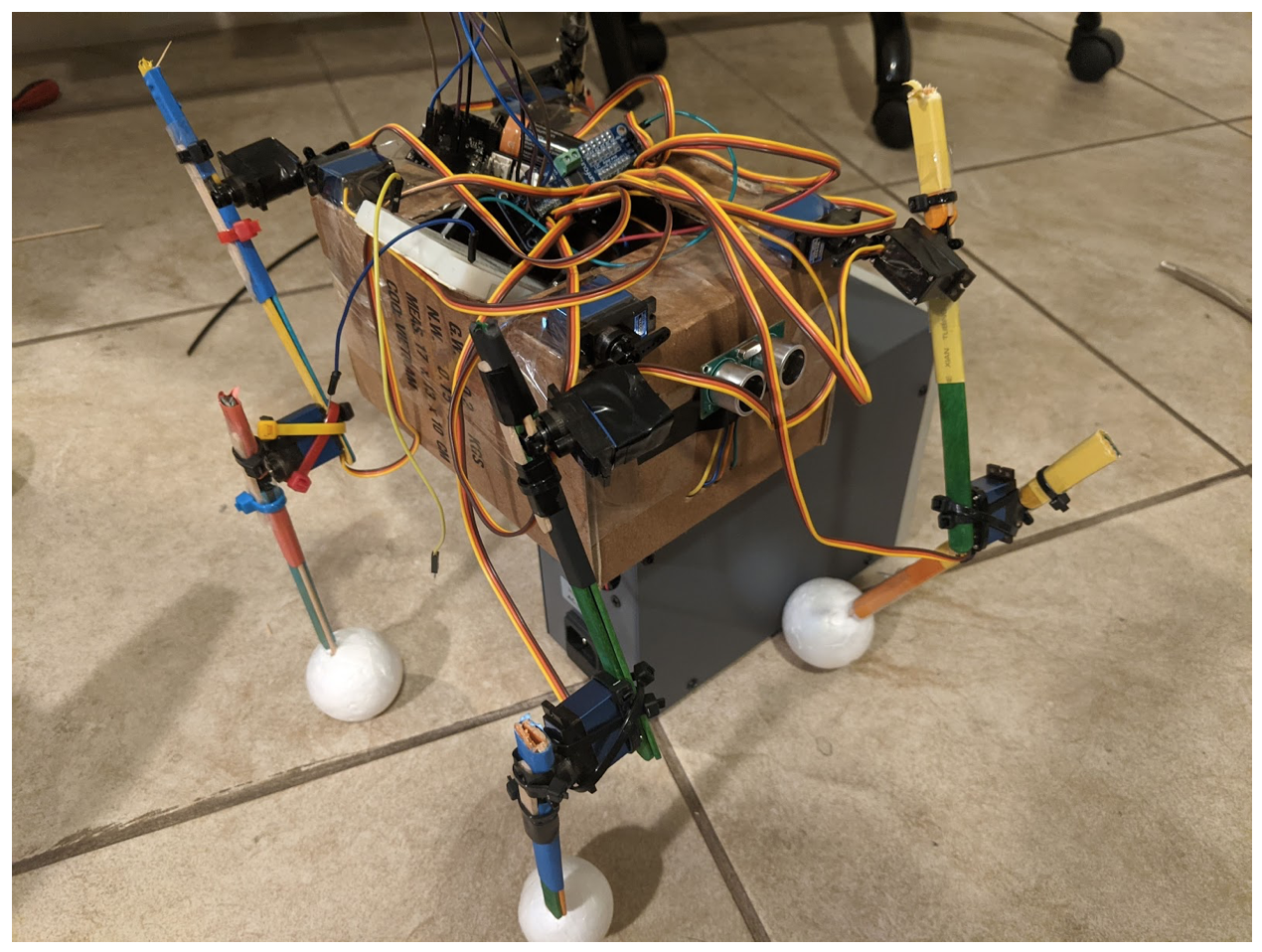
Figure(17). Demo prototype
System Design / Final Design and Results
System Block Diagram
Author/s: Dino Asmar, Domingo Sainz
Verification: Dino Asmar
Approval: Dino Asmar
The system block diagram is like the schematic showing what is connected together except it’s simplified. When making a schematic I think this may be the best way to start. Getting a general idea of what is needed then using this to connect actual components virtually with a fritzing app for a more detailed view. The arrows show the direction of the signal like for example the servos just receive while the ultrasonic sensor not only receives but also sends to the 3dot board. The color isn’t needed for this simple diagram but for larger diagrams color might help group things together into a category that can later be used for the product breakdown structure or for the work breakdown structure.
Figure(18). System Block Diagram
After reviewing what parts were needed, we created a preliminary system design to show how each component will interface with each others. The diagram is based on the datasheets to make sure the pin to pin connections are correct. The preliminary system design includes the 3DoT board, power boost, servo driver, 12 MG92B micro servos, and ultrasonic sensors all powered by the 3.7V battery.
The first iteration of the design also included two ultrasonic sensors that were later reduced to one and an LDR photoresistor that was later removed from the design.
Interface Definition
Author/s: Domingo Sainz
Verification: Dino Asmar
Approval: Dino Asmar
One matrix is made to show how the pins will be connected. The pins in front of the 3dot are grouped together and highlighted to show they are meant for a front shield while the rest of the 3Dot pins are highlighted for a top shield. The top row shows all components that are used while the rows below show what pins are connected together.
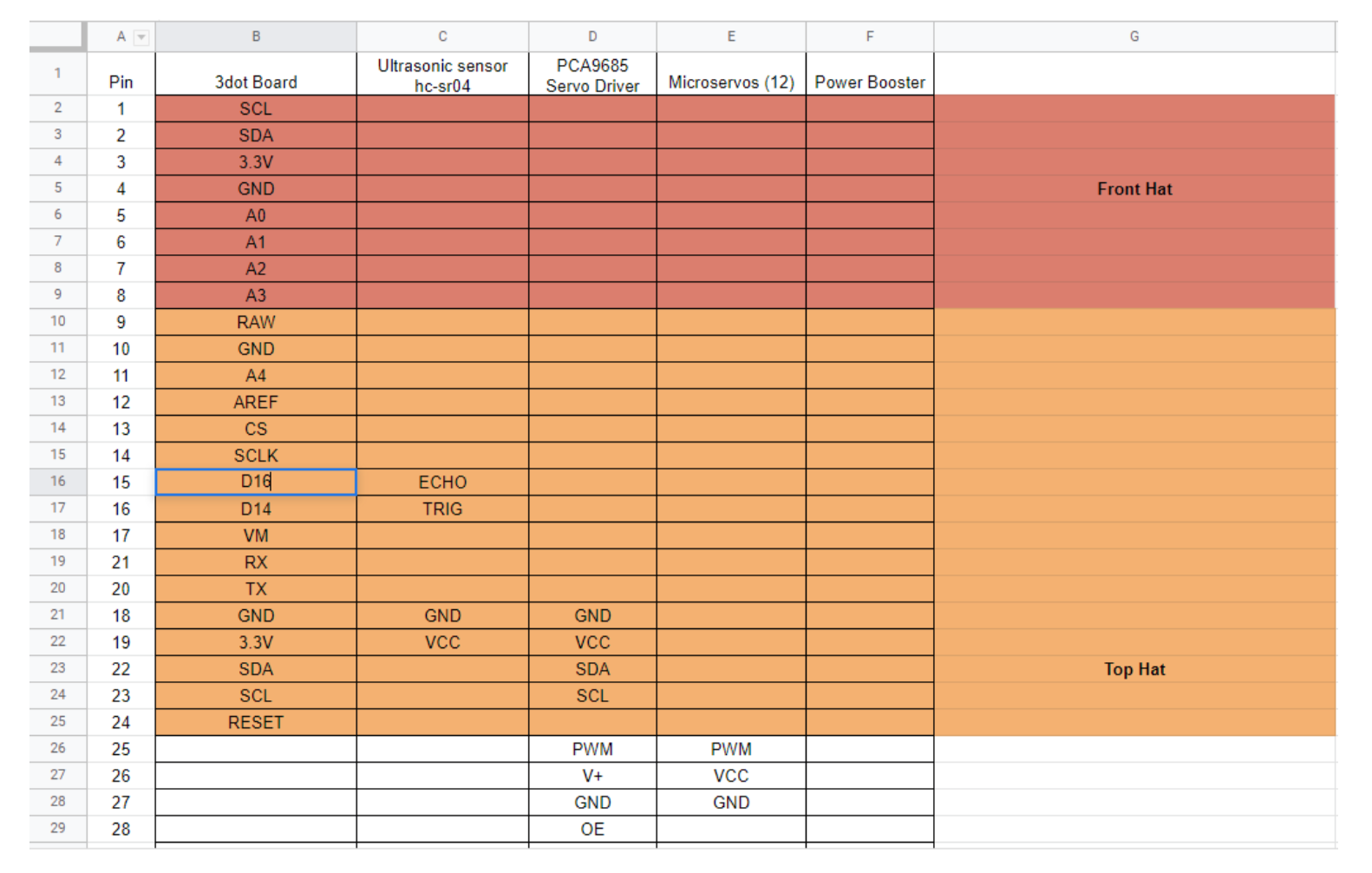
Figure(19). Interface Matrix
Modeling/Experimental Results
Author/s: Joseph Harman, Dino Asmar
Verification: Dino Asmar
Approval: Dino Asmar
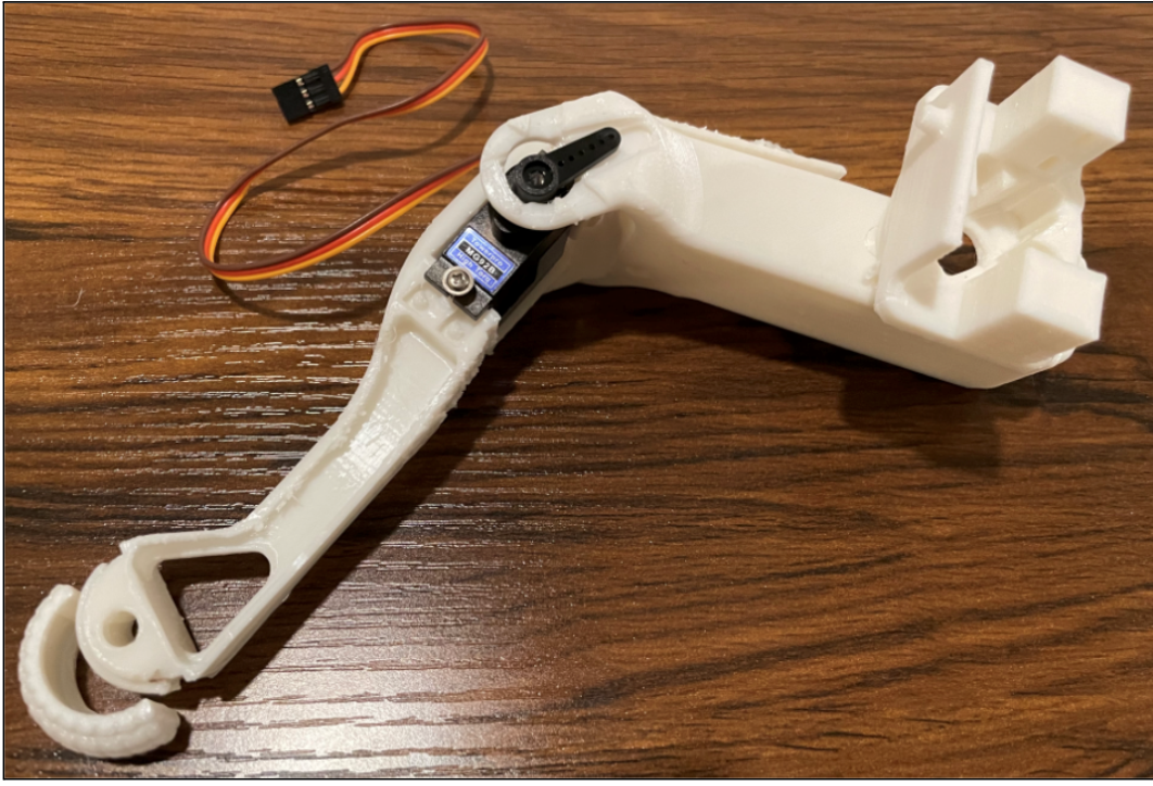
When the prototype of the Microspot was first designed, the legs did not move properly, due to the scaling down of the model. The design team added a plastic bearing in order to help the micro servos to operate more smoothly.
Here is the earlier code, it was done to test the 3 servos and ultrasonic sensor.
uint32_t mydelay;

int trig = 16; //assigned the ultrasonic to the correct pins on Arduino uno
int echo = 15;
Servo servo;
void setup() {
  Serial.begin(9600);
  pinMode(trig, OUTPUT);
  pinMode(echo, INPUT);
  servo.attach(17);
  mydelay = millis + 1000;
}

void loop() {
  ArxRobot.loop();
  digitalWrite(trig, LOW); //Low: No output needed
  delay(0.002);
  digitalWrite(trig, HIGH); //Send Pulse 8 Bytes
  delay(0.01);
  digitalWrite(trig, LOW); //No data send, waiting on the 8 Bits to received.
  int duration = pulseIn(echo, HIGH); //until Echo is high which is in the receiving mode.
  int distances = (duration / 2) * 0.0343; //Pulse goes once and return so we devided by two. So, distance be accurate
  if (distances < 20) {
    servo.write(120);
    if (millis > mydelay){
      mydelay = millis + 1000;
      servo.write(90);
    }

  else if ( distances < 20) { //In this code the main goal is for the micro servo to run until ultrasonic detects an obstacle within 20 cm. Once Ultrasonic detects an obstacle then it will stop the micro servos for an emergency stop.
  loop();
  }
}
The original SpotMicro model was designed to use regular size servos motors. A requirement for our project was to use micro servo motors and a 3DoT board. In order to use the micro servos, we needed to scale our model down so that the model would be small enough for the micro servo to have enough power to move the parts without struggling, and the model needed to be scaled to be proportional to the micro servo motors.
In the Autodesk Fusion 360 program, I used the scale function to resize the model as close as possible to the size that will properly hold the micro servo. From here, I then extruded different walls in the micro servo mounting area to make a more close fit so the micro servo would not move around easily. This needed to be applied to the 12 micro servo mounting area
Figure(20). Leg Assembly Before Scale
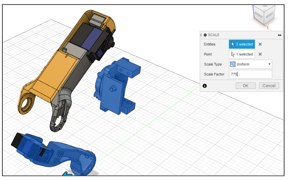
Figure(21). Leg Assembly After Scale
Bolt & Nut Area Modification
The original servo motor uses 4 bolts and 4 nuts to mount into place. The MG92B micro servo that we used needed 2 bolts and 2 nuts to mount into place. Because the original SpotMicro model was designed for the 4 bolt pattern, I had to then modify the mounting pattern to use 2 bolts and 2 nuts centered instead of the 4 bolts and 4 nuts from the original model.
For this process, I needed to fill in the original bolt holes and fill in the original nut area. I then needed to create all-new centered holes on each side and then add new cutouts for the nut to fit into and not move when the bolt is inserted and tightened. This all needed to be applied to the 12 micro servo mounting areas. After, every hole in the model needed to then be downsized from the 4mm that the original SpotMicro model used to fit 2mm bolts and nuts with a small tolerance that our model required.
Micro Servo Arm Mounting Area Modification
After scaling our model down, the MG92B servo arm did not fit in the 12 different mounting locations. The model’s servo arm locations were also designed for servo arms with a different pattern than ours. To fix this, I erased the servo arm mounting pattern from the different locations and started from scratch to mold the mounting locations to the MG92B servo arm size and pattern that we had.
The servo arm locations also did not have much depth when the servo arms were mounted in the arm cutout, which could lead to the servo arm slipping out while the micro servo motor was operating. In order to fix this, I made the micro servo arm cut out deeper in order for the arm to have less of a chance of slipping out of the location. This all needed to be applied to the 12 micro servo arm mounting areas.
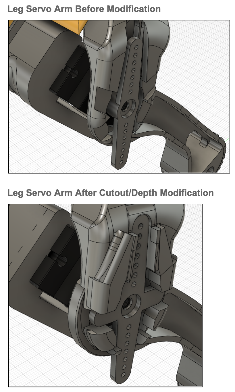
Figure(22). Servo and Arm modifications
There were some experiments regarding the code, the legs, and the angles of the legs. Here is the link to the video . The video provided is an experiment to see the joint of the leg.
Next, the prototype was made for the software team in order to test the code and see the behavior of the leg in the prototype version of the MicroSpot.
After running and testing the prototype the arm came out to be not designed perfectly, as a result, the design team, checked on the issue and fixed it in the following update of the 3D model.
Figure(23).Prototype Model

Figure(24).Arm came out, screw hole issue
Mission Command and Control
Author/s: Dino Asmar, Domingo Sainz
Verification: Dino Asmar
Approval: Dino Asmar
3DoT Robots
| Hardware | Software |
| Personal Computer | Arxterra Control Panel |
| Smartphone | ArxRobot App |
| 3DoT Board | Arduino and Robot3DoT Library |
Software block diagram:
- In the software diagram, we show how commands from the user are sent and used by the Microspot. It starts with the user using the Arxterra app on their phone to send out 1 of five commands to the 3Dot via Bluetooth. Then the 3Dot sends the command to the servo driver IC via the SCL and SDA pins. The servo driver finally sends the actions to each group of servos. The ultrasonic sensor will also send data to the 3Dot board and will override commands from the app to stop the robot from walking and colliding with an object that is in front of it.
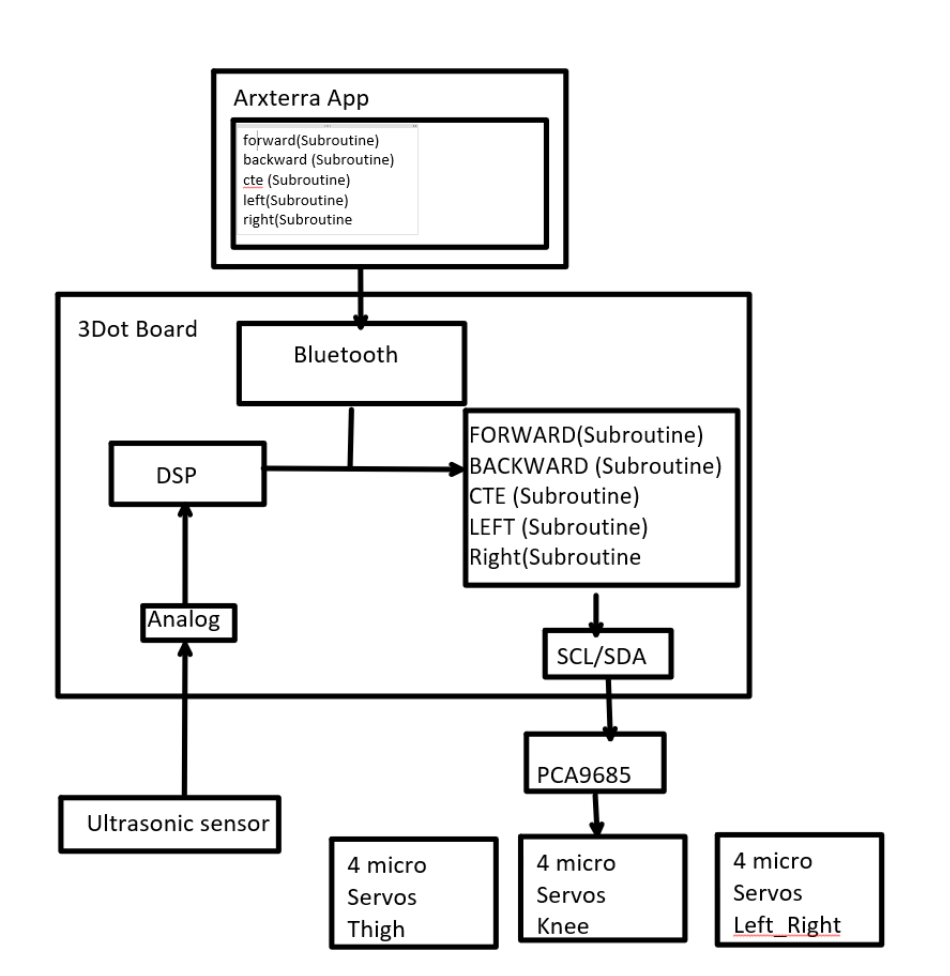
Figure(25). Software Block Diagram
Using an Arxterra App for an IOS devices phone, the custom command was added and designed to control the speed of the micro servos when operating. Here is the costume command using the select options. The second photo is the ID commands that when is sent to the software, the software calls the desired function in order to move in all four directions.
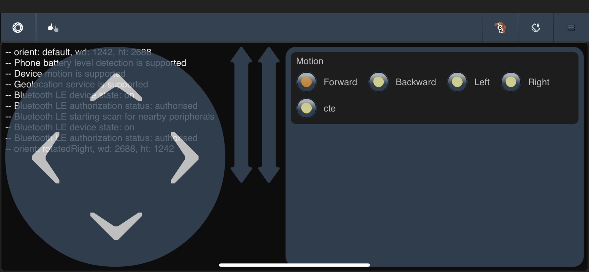
Figure(26). Adding Costume Commands
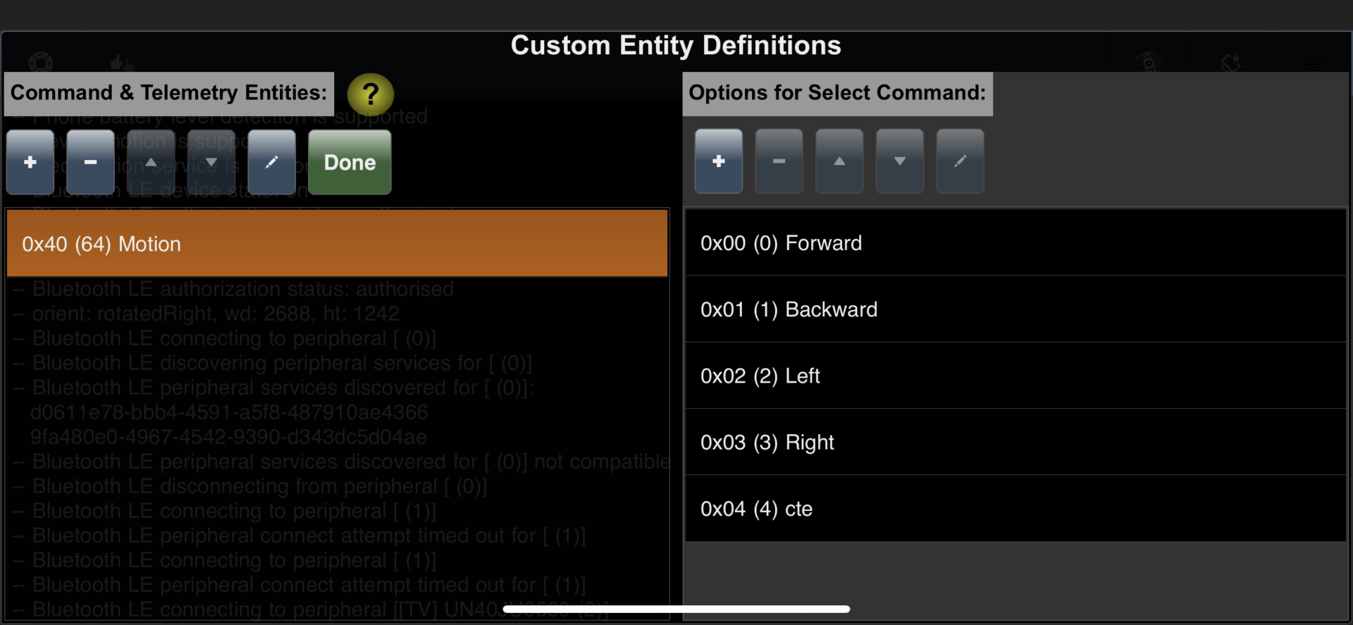
Figure(27). Adding Costume Commands
Electronic Design
Author/s: Dino Asmar, Domingo Sainz
Verification: Dino Asmar
Approval: Dino Asmar
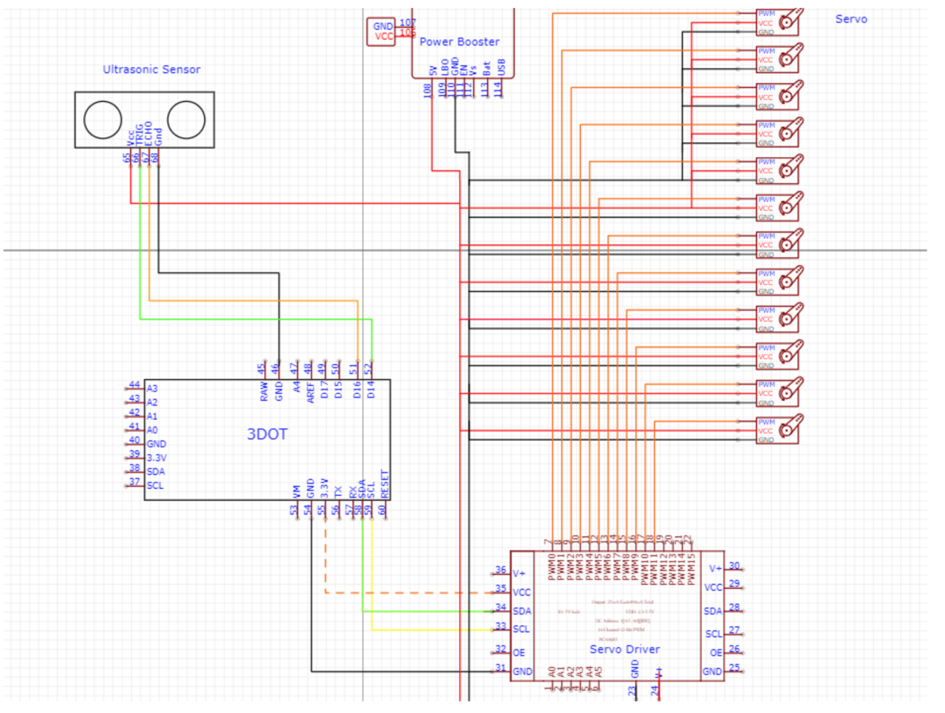
I used an online website called EasyEDA to make the schematic for our microspot. I later learned about Fritzing however it seemed pointless to make the schematic again. I used the actual pins from all the components we planned on using and if I would have tried making this schematic in fritzing I would had to make a 3dot part which would be a waste of time. I could use an Arduino to represent the 3dot but that wouldn’t show the actual pins the 3dot has to offer. The ultrasonic sensors were an issue when I first started making this diagram because I didn’t know where they could go on the 3dot but I managed to find some analog sensors that can use the front analog pins of the 3Dot.
- Level 1 requirements
- Should use a 3Dot Board
- Microspot will use micro servos
- Level 2 requirements
- An external 5v power source will be used to power the 12 micro servos and ultrasonic sensors.
- Microspot will use ultrasonic sensors to avoid crashing into obstacles by turning left or right.
-
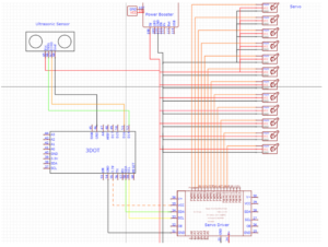
Figure(28). Schematic
PCB Design
Verification: Dino Asmar
Approval: Dino Asmar
PCB Schematic
Introduction: This blog post will cover the custom PCB that will act as the top shield for the 3dot. For this PCB we used adafruit’s servo driver as an example of what we would need for our board. The PCB will use the same IC as adafruit’s servo driver but we used different sized resistors and capacitors so that assembly would be easier. The PCB was designed at first to have the power booster lay on top of it to make connecting even easier except the design was changed to use a terminal block instead of with reverse voltage protection that was copied from adafruit’s board.
Related Requirements:
Level 1 Requirements
- Should use a 3Dot Board
- Microspot will use micro servos
Level 2 Requirements
- An external 5v power source will be used to power the 12 micro servos and ultrasonic sensors.
- The custom PCBs should fit in the MicroSpot chassis.
- PCB Board explanation:
As mentioned in the introduction this PCB was designed to fit on top of the 3Dot board with the PCB going outwards allowing more space to be used without it interfering with the 3Dot’s battery. To meet some of the requirements involving servos, this PCB uses a PCA9685 IC which is the same that Adafruit uses in their servo driver however due to shortages of the specific IC I am now using the PCA9532 which is similar to the PCA9685 however with fewer pins that aren’t really needed. With the PCB redesigned to use the PCA9532 it should meet the requirements of microspot using servos. Another requirement that is met is the servos using an external power source. The PCB has a terminal block to allow an external power source to power the servos, additionally, another set of pins is added opposite of the terminal block for a second option to power the servos. Some capacitors are added as well near the IC to reduce any noise that could affect it.
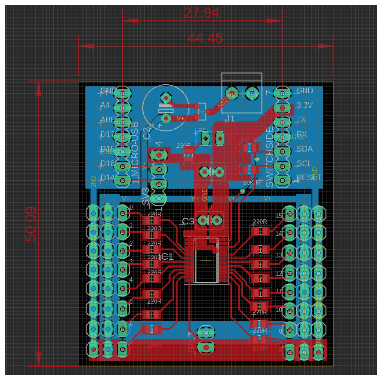
Figure(29). Costume PCB
Firmware
Author/s: Domingo Sainz
Verification: Dino Asmar
Approval: Dino Asmar
In the software diagram, we show how commands from the user are sent and used by the Micro spot. It starts with the user using the Arxterra app on their phone to send out 1 of five commands to the 3Dot via Bluetooth. Then the 3Dot sends the command to the servo driver IC via the SCL and SDA pins. The servo driver finally sends the actions to each group of servos. The ultrasonic sensor will also send data to the 3Dot board and will override commands from the app to stop the robot from walking and colliding with an object that is in front of it.
Figure(30). Software Block Diagram
Author: Dino Asmar
Please use the reference section to see the actual link to the code and firmware
// Dino Asmar
// EE400D
// MicroSpot Firmware
//************************************* library for servos
#include
#include
//******************************************************* setup servos
Adafruit_PWMServoDriver pwm = Adafruit_PWMServoDriver();

#define SERVOPOSMAX 2300
#define SERVOPOSMIN 500
//********************************************** connect to i2c DRIVER
int Servo_Knee[4] = {0, 1, 2, 3}; // -----> BL ,BR ,FL ,FR
int Servo_Thigh[4] = {4, 5, 6, 7}; // -----> BL, BR, FL, FR
int Servo_Left_Right[4] = {8, 9, 10, 11}; // -----> BL, BR, FL, FR
//*********************************** library for set commands
#include
#include

//************************************** setup library arxrobot for add comammds
ArxRobot ArxRobot;
const uint8_t CMD_LIST_SIZE = 1; // we are adding 1 commands coming soon we should added to 1
#define MOTION 0x40
uint8_t Action = 0; //This Global variable will hole the action that user currently selected.
#define FWD 1
#define BWD 2
#define LFT 3
#define RGT 4
#define STND 5
//***************************************************************** set commands
bool motionHandler(uint8_t cmd, uint8_t param[], uint8_t n)
{
PORTD |= 0b00100000; //Turning ON the LED
delay(1000);
PORTD &= 0b11011111; //Making sure that LED is OFF
delay(1000);
if (param[0] == 0x00) { //Here I am assigning the Action to become FWD since select option that moves forward has a 0x00 ID.
Action = FWD;
}
if (param[0] == 0x01) {
Action = BWD;
}
if (param[0] == 0x02) {
Action = LFT;
}
if (param[0] == 0x03) {
Action = RGT;
}
if (param[0] == 0x04) {
Action = STND;
}

return false;
}

ArxRobot::cmdFunc_t onCommand[CMD_LIST_SIZE] = {{MOTION, motionHandler}};
//************************************* ultrasonic connect to 3dot

// Previous variable saves the previous angle and save it, and the new angles startes from the previous angle. For example;
// when micro servo number1 moves to the 40 degrees, next move of the micro servo number1 will be 40 degrees plus another 40 degrees. This method will
// help the micro servo to hold the old angle and apply the new angle to the move.
//int previous = 0;
void setup()
{
Serial.begin(9600);

//************************************************** setup for ArxRbot library and active it
ArxRobot.begin();
ArxRobot.setCurrentLimit(60);
ArxRobot.setOnCommand(onCommand , CMD_LIST_SIZE);
//**************************************************
DDRD |= 0b00100000; //Setting PDF5 to be an output
PORTD &= 0b11011111; //Making sure that LED is OFF
//********************************************* setup function about servos
pwm.begin();
pwm.setOscillatorFrequency(27000000);
pwm.setPWMFreq(60);

delay(10);

}

void loop()
{
ArxRobot.loop();

if (Action == FWD) {
forward();
}
else if (Action == BWD) {
backward();
}
else if (Action == LFT) {
left();
}
else if (Action == RGT) {
right();
}
else if (Action == STND) {
cte();
}

}
void cte()
{
//*************************************************************** Orientation of knees and thigh
Position(Servo_Knee[0], 0, 180 ); // First data represent the angle of the micro servo, and second data value represent which micro servos are going to receive the data.
Position(Servo_Knee[2], 0, 180 );

Position(Servo_Knee[1], 180, 0 );
Position(Servo_Knee[3], 180, 0 );

Position(Servo_Thigh[0], 0, 180 );
Position(Servo_Thigh[2], 0, 180 );

Position(Servo_Thigh[1], 180, 0);
Position(Servo_Thigh[3], 180, 0);

// Position(Servo_Left_Right[0, 1, 2, 3], 0, 90 );
}

void forward()
{
// Those comments out commands are mainly for the debugging porpuses and the way that I can debug the code is by using those commands. Leave it comment out
//previous = 40;
Position(Servo_Knee[0], 40, 60 );
//previous = 140;
Position(Servo_Knee[3], 140, 120 );

// Position(Servo_Knee[1,3],Position (120) );
// delay(500);

//previous = 140;
Position(Servo_Thigh[0], 140, 120 );
//previous = 40;
Position(Servo_Thigh[3], 40, 60 );

// Position(Servo_Thigh[1,3],Position (60) );
// delay(500);

//previous = 60;
Position(Servo_Knee[0], 60, 40 );
//previous = 120;
Position(Servo_Knee[3], 120, 140 );

// Position(Servo_Thigh[1,3],Position (140) );
// delay(500);

//previous = 140;
Position(Servo_Knee[1], 140, 120 );
//previous = 40;
Position(Servo_Knee[2], 40, 60);

// delay(500);

//previous = 120;
Position(Servo_Thigh[0], 120, 140 );
//previous = 60;
Position(Servo_Thigh[3], 60, 40 );

// Position(Servo_Knee[1,3],Position (40) );
// delay(500);

//previous = 140;
Position(Servo_Thigh[1], 140, 120 );
//previous = 40;
Position(Servo_Thigh[2], 40, 60 );

// delay(500);

//previous = 120;
Position(Servo_Knee[1], 120, 140 );
//previous = 60;
Position(Servo_Knee[2], 60, 40 );

// delay(500);

//previous = 40;
Position(Servo_Knee[0], 40, 60 );
//previous = 140;
Position(Servo_Knee[3], 140, 120 );

//previous = 120;
Position(Servo_Thigh[1], 120, 140 );
//previous = 60;
Position(Servo_Thigh[2], 60, 40 );

//previous = 60;
Position(Servo_Knee[0], 60, 40 );
//previous = 120;
Position(Servo_Knee[3], 120, 140);

// delay(500);
}

void backward()
{
//previous = 40;
Position(Servo_Knee[0], 40, 60);
//previous = 140;
Position(Servo_Knee[3], 140, 120 );

// Position(Servo_Knee[1,3],Position (120) );
// delay(500);

//previous = 140;
Position(Servo_Thigh[0], 140, 160 );
//previous = 40;
Position(Servo_Thigh[3], 40, 20 );

// Position(Servo_Thigh[1,3],Position (60) );
// delay(500);

//previous = 60;
Position(Servo_Knee[0], 60, 40 );
//previous = 120;
Position(Servo_Knee[3], 120, 140);

// Position(Servo_Thigh[1,3],Position (140) );
// delay(500);

//previous = 140;
Position(Servo_Knee[1], 140, 120 );
//previous = 40;
Position(Servo_Knee[2], 40, 60 );

// delay(500);

//previous = 160;
Position(Servo_Thigh[0], 160, 140);
//previous = 20;
Position(Servo_Thigh[3], 20, 40 );

// Position(Servo_Knee[1,3],Position (40) );
// delay(500);

//previous = 140;
Position(Servo_Thigh[1], 140, 160 );
//previous = 40;
Position(Servo_Thigh[2], 40, 20 );

// delay(500);

//previous = 120;
Position(Servo_Knee[1], 120, 140 );
//previous = 60;
Position(Servo_Knee[2], 60, 40 );

// delay(500);

//previous = 40;
Position(Servo_Knee[0], 40, 60);
//previous = 140;
Position(Servo_Knee[3], 140, 120 );

//previous = 160;
Position(Servo_Thigh[1], 160, 140 );
//previous = 20;
Position(Servo_Thigh[2], 20, 40);

//previous = 60;
Position(Servo_Knee[0], 60, 40 );
//previous = 120;
Position(Servo_Knee[3], 120, 140);
}

void left()
{
for (int y = 0; y <= 1; y++)
{
int Lefts = 2 * y + 1;
//previous = 40;
Position(Servo_Knee[Lefts], 40, 60 );
//previous = 90;
Position(Servo_Left_Right[Lefts], 90, 100 );

//previous = 60;
Position(Servo_Knee[Lefts], 60, 40 );
//previous = 100;
Position(Servo_Left_Right[Lefts], 100, 90);

int Rights = 2 * y;
//previous = 140;
Position(Servo_Knee[Rights], 140, 120);
//previous = 90;
Position(Servo_Left_Right[Rights], 90, 80);

//previous = 120;
Position(Servo_Knee[Rights], 120, 140);
//previous = 80;
Position(Servo_Left_Right[Rights], 80, 90 );
}
}
void right()
{
for (int y = 0; y <= 1; y++)
{
int Lefts = 2 * y + 1;
//previous = 40;
Position(Servo_Knee[Lefts], 40, 60 );
//previous = 90;
Position(Servo_Left_Right[Lefts], 90, 80 );

//previous = 60;
Position(Servo_Knee[Lefts], 60, 40);
//previous = 80;
Position(Servo_Left_Right[Lefts], 80, 90);

int Rights = 2 * y;
//previous = 140;
Position(Servo_Knee[Rights], 140, 120 );
//previous = 90;
Position(Servo_Left_Right[Rights], 90, 100 );

//previous = 120;
Position(Servo_Knee[Rights], 120, 140 );
//previous = 100;
Position(Servo_Left_Right[Rights], 100, 90 );
}
}

void Position( int leg, int previous , int ang)
{
int pulse = map(ang, 0, 180, SERVOPOSMIN, SERVOPOSMAX);
//Serial.print("Angle :");
//Serial.print(ang);
//Serial.print("pulse :");
//Serial.print(pulse);
//return pulse;

int Previous_F = map(previous, 0, 180, SERVOPOSMIN, SERVOPOSMAX);
//Serial.print("previous :");
//Serial.print(previous);
//Serial.print("Previous_F :");
//Serial.println(Previous_F);

//return Previous_F ; return pulse;

for (Previous_F; Previous_F < pulse; Previous_F++)
{
pwm.writeMicroseconds(leg, Previous_F);
// delay(3);
}

for (Previous_F; Previous_F > pulse; Previous_F--)
{
pwm.writeMicroseconds(leg, Previous_F);
// delay(1);
}
// return Previous_F && pulse;

}
Mechanical/Hardware Design
Author/s: Joseph Hartman
Verification: Dino Asmar
Approval: Dino Asmar
For our project, we were tasked to create a quadruped robot dog with the appearance of the Boston Dynamics Spot dog. We located a model of a robot dog inspired by the Boston Dynamics Spot on the open-source website Thiniverse. The model needed quite a few modifications in order to fit our requirements and the modifications are described below.
List of Parts
To get an understanding of the MicroSpot, we needed to review the assembly file of the model to see what parts the model consists of. Here we could see how the parts attach to each other and where the mounting locations are. Also, we reviewed the quantity of what parts were needed and what parts needed to be designed and added to the model. After reviewing the model, we could see how many micro servos we will need and what other electrical components would be needed to allow the MicroSpot to turn on and walk.
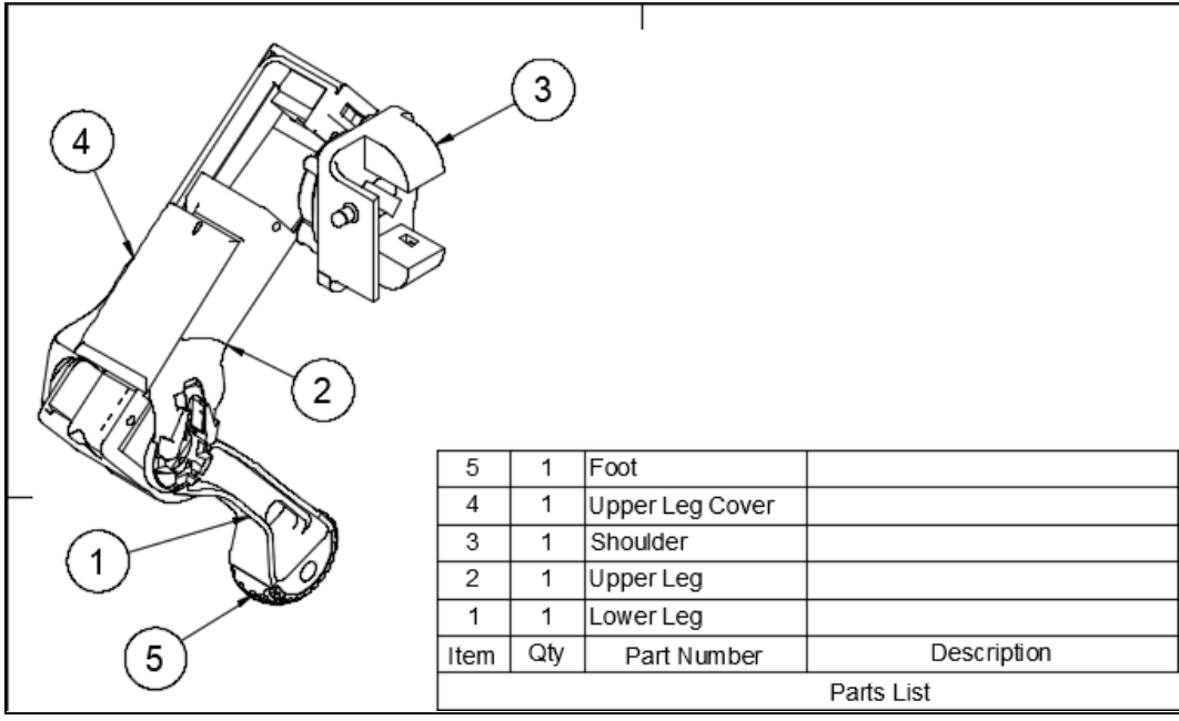
Figure(31). List of Parts 1
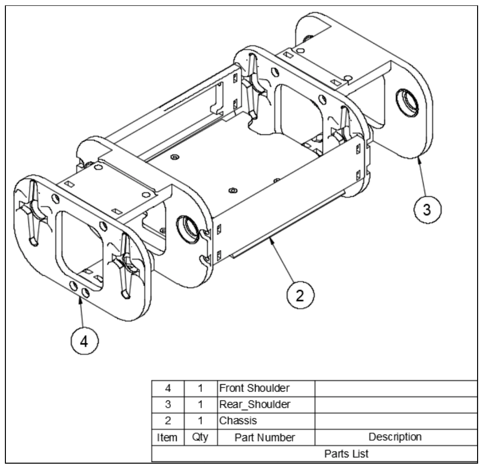
Figure(32). List of Parts 2
Figure(33). List of parts 3
Bolt & Nut Area Modification
The original servo motor uses 4 bolts and 4 nuts to mount into place. The MG92B micro servo that we used needed 2 bolts and 2 nuts to mount into place. Because the original SpotMicro model was designed for the 4 bolt pattern, I had to then modify the mounting pattern to use 2 bolts and 2 nuts centered instead of the 4 bolts and 4 nuts from the original model.
For this process, I needed to fill in the original bolt holes and fill in the original nut area. I then needed to create all-new centered holes on each side and then add new cutouts for the nut to fit into and not move when the bolt is inserted and tightened. This all needed to be applied to the 12 micro servo mounting areas. After, every hole in the model needed to then be downsized from the 4mm that the original SpotMicro model used to fit 2mm bolts and nuts with a small tolerance that our model required.

Figure(34). Bolt & Nut Area Modifications
The original SpotMicro model was designed to use regular metal bearings. After scaling our model down, the original bearing locations needed to be redesigned to use a smaller bearing. To prototype faster and make the design easier, I 3D printed a bearing that could be used on the model in the 8 different bearing locations.
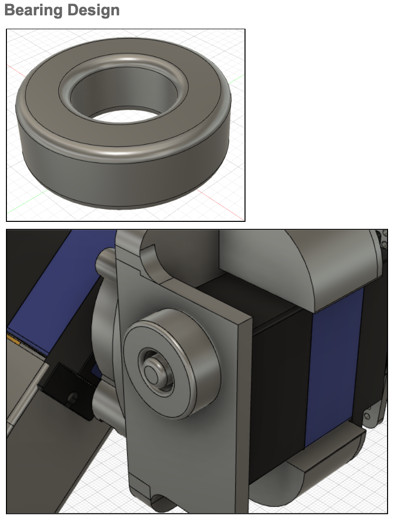
Figure(35). Bearing Design
Structural Support
After 3D printing some parts, it was noticeable that weak points exist within different parts of the model. To prevent parts from breaking when the MicroSpot walks, I added support to the different weak points by strengthening thin pieces with more material or different designs. I then printed out test 3D prints in order to see that the structural support made the part stiffer and less likely to break.
Figure(36). Structural Support
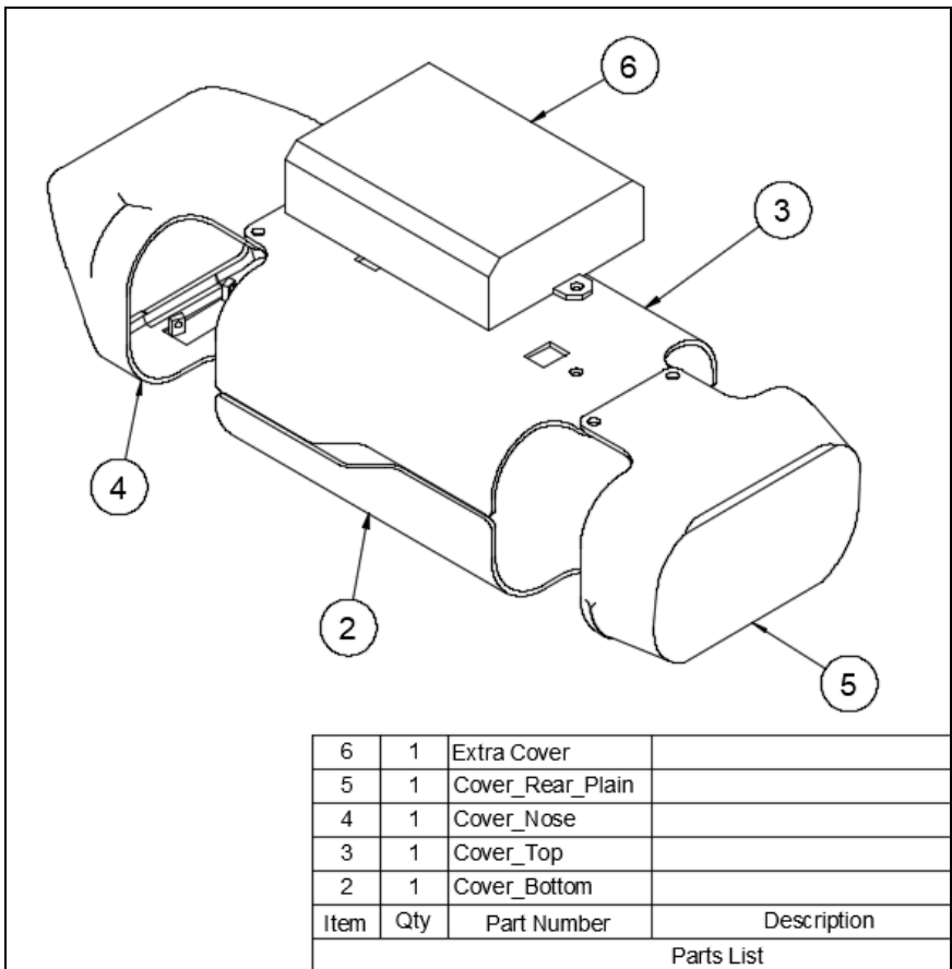
Battery Cover
After scaling the SpotMicro model down, we could see that the area inside of the chassis would not be sufficient enough for the battery, 3DoT, Servo Driver and Powerboost. To help fix the issue, I designed an extra cover to allow for the battery to sit on top of the model and outside of the chassis, freeing up room inside of the chassis for other electronics. I then made holes in the top cover for the battery wires to connect into the chassis.
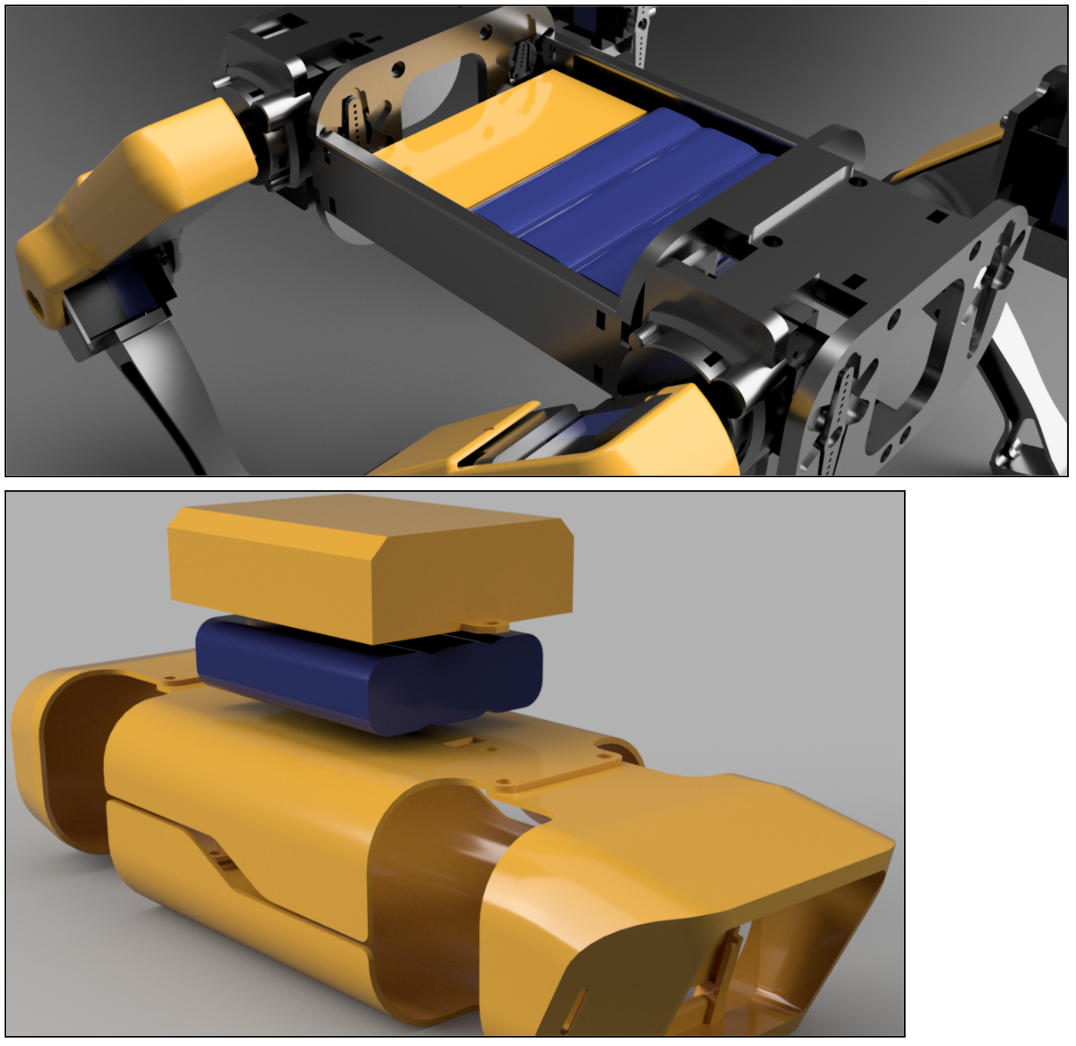
Figure(37). Battery Pack
After 3D printing some parts, it was noticeable that weak points exist within different parts of the model. To prevent parts from breaking when the MicroSpot walks, I added support to the different weak points by strengthening thin pieces with more material or different designs. I then printed out test 3D prints in order to see that the structural support made the part more stiff and less likely to break.
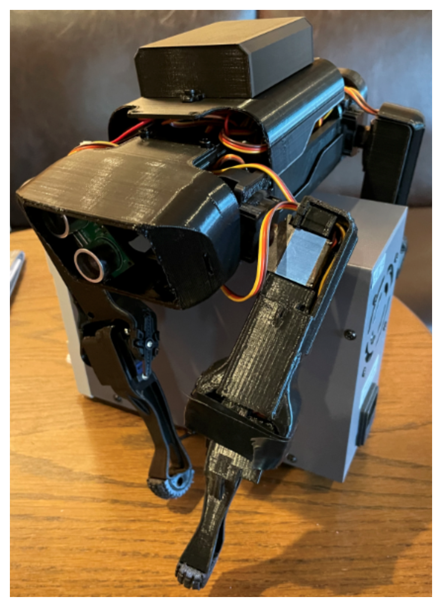
Figure(38). Prototype
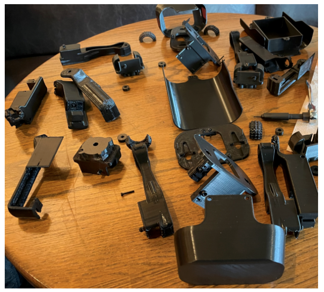
Figure(39). Parts for the Prototype
Verification & Validation Test Plan
Author/s: Dino Asmar, Joseph Hartman, Domingo Sainz
Verification: Dino Asmar
Approval: Dino Asmar
Our plan is to make sure that every single of the level one and level two requirements can meet and is verifiable and then we be able to validate it. The verification test plan is designed for the team to make sure the project that was built is operating correctly and meeting all of those requirements. Our plan is to test and verify if Microspot is going to be able to operate and walk in the real world.
Concluding Thoughts and Future Work
Author/s: Dino Asmar, Joseph Hartman, Domingo Sainz
Verification: Dino Asmar
Approval: Dino Asmar
As a project manager of this project, it is important for the team members and everyone in the team to know and start learning their material in the early weeks. Make sure to do lots of studies at the beginning of the semester and test and modify as much as you can until you achieve your desired result. Being an online class, made my situation difficult especially since not living close to the team member was stressful. Overall, Microspot project was derived from a real-world project and all the tasks and the process that was made in order to achieve our desired goal were simulations of the real-world example. My suggestion for future students is three simple sentences, assign the role to the right team member, respect the deadlines, and test your result multiple times.
Do research on the components you plan on using and make sure everything can connect with each other. If possible test the circuit out as soon as possible to avoid having the issue of redesigning everything at the end. Luckily we didn’t have that issue except with the battery but if it was a different component then we would be in trouble. If you plan on making a custom pcb try finding the files that are similar to what you wish to make so that you have a better idea of where to start. Also start as soon as possible in pcb making because the board goes through many changes. I made many versions of my board and I made sure to save them separately in case I needed to go back to at some point in the boards life cycle and start from there. When designing the pin locations on your board always check it is correct and that it will fit on the 3dot. The battery holder can interfere with the top shield pcb so remember to keep that in mind. Draw pictures of what you wish to make and how it will be used so that you can visually see it. Finally, I would like to say that the pandemic shows how difficult it is to get things done compared to if we would have been working in a school but we did learn how to adapt to our situation and still get things done.
References/Resources
Author/s: Dino Asmar
Verification: Dino Asmar
Approval: Dino Asma
These are the starting resource files for the next generation of robots. All documentation shall be uploaded, linked to, and archived into the Arxterra Google Drive. The “Resource” section includes links to the following material.
- Project Video YouTube
- PDR (PowerPoint, Prezi, or PDF)
- Project Libre Schedule and Tasks
- Cost File
- Mass / Power share resource Files
- Verification and Validation test plan
- Arduino and/or C++ Code
- Complete Bill of Materials (BOM) with vendor names for both mechanical and electrical parts.
- Demo Video Using 3 micro servos and Ultrasonic Sensor to test the code
Resources
- Boston Dynamics Spot
- Microspot Model
- Thingiverse