Executive Summary
The robotic arm will be tasked with picking up objects with its end effector and be able to support a small camera. The robot will be able to complete these tasks with two brushless motors and two stepper motors to accomplish its tasks. The controls for the motor will be wireless so they can be controlled at a distance with Bluetooth technology. The design will incorporate the use of an Arduino mega.
Program and Project Objectives
Program Objectives:
The team has been tasked with the design of a robotic arm that will be mounted on Unitree Go1 Pro robot dog. This arm will be operated while Go1 Pro is traveling in the Japanese Garden at California State University while it is traveling the arm will be assigned with to perform that will aid the dog.
Project Objective:
The arm will be remote operated and given instructions as to move the directions while carrying a sport action camera, and utilize it clamp to pick up items
Mission Profile
The original mission had the robotic arm being mounted on the unitree go 1 pro robotic dog which was abandoned due to the constraints that we faced with the payload of the dog. The updated design of the robotic arm will be able to pick up objects with its end effector while having three degrees of freedom. It will also be able to be controlled at a distance with a Bluetooth module that will be connected to an Arduino microprocessor.
Requirements
Every subsystem shall be tested and verified in tandem with the engineering constraints and standards. The level one requirements only describe the overview of the project while not being design solutions. While the level two requirements are subsystems that are necessary for the design. The level two requirements each have a corresponding level one requirement.
LEVEL 1 REQUIREMENTS
L-1.1 The production cost of the robotic arm shall not exceed $200.
L-1.2 The robotic arm shall have three degrees of motion.
L-1.3 The robotic arm shall be controlled at a distance with a Bluetooth module(HC05).
L-1.4 The robotic arm shall utilize a custom 3d design using Solidworks.
L-1.5 The robotic arm will employ the use of a custom Printed-Circuit Board(PCB) design.
L-1.6 The robotic arm will have an end effector to grip objects.
L-1.7 The robotic arm shall be able to support a small camera.
LEVEL 2 REQUIREMENTS
L-2.1 L-1.1 shall be achieved by utilizing the Innovation space to 3d print the 3d design and using repurposed motors from older projects.
L-2.2 L-1.2 shall be accomplished with the use of two brushless motors and two stepper motors.
L-2.3 L-1.3 shall connect a Bluetooth module HC05 to an Arduino mega board which will be controlled through Arduino ide software in tandem with an app developed with MIT App Inventor.
L-2.4 L-1.4 The parts necessary shall be created and dimensioned through solid works.
L-2.5 L-1.5 The custom PCB design will be on Eagle cad we will design auxiliary to expand the capabilities of the Arduino mega.
L-2.6 L-1.6 An stepper motor will be utilized to operate and is attached to the 3D printed clamp.
L-2.7 L-1.7 The arm shall be able to handle a load of the camera which will be demonstrated by the torque analysis.
Applicable Engineering Standards
Project/Economic
Subcategories: Cost, Extensibility, Interoperability, Maintainability, Quality, Marketability, and Schedule
All 3DoT robots shall be constrained to a a Cost not to exceed $250.
All project Schedules shall be constrained to a completion date of Tuesday December 18, 2018. Project completion includes documentation and materials purchased by or loaned to the project.
One of the Economic Factors affecting our robots are return rates. To demonstrate the durability and child friendliness of our robot a simple drop test from 1.4 meter shall be performed. The height is defined by the average height of an average 11 year old girl.
Extensibility is designed into the 3DoT board by way of one 8-pin 100 mil connector located on the front of the board and two 8-pin 100 mil connectors located on the top of the board. By plugging shields into these connectors, the 3DoT board can support a diverse set of robots. All robots shall contain one or more custom designed 3DoT shields. The 3DoT shield(s) incorporating interface electronics between the 3DoT board and sensors and/or actuators unique to the robot. Surface Mount Technology (SMT) will be employed unless a waiver for through-hole parts is granted.
Maintainability: Disassemble and Reassemble of the robot shall be constrained to less than 20 minutes (10 + 10 minutes). Disassembly: The 3Dot board is clear of all other electronic and mechanical subassemblies. All electronic and mechanical subassemblies and associated connectors, sensors, and actuators including motors are disconnected. A functional test of the robot is conducted after reassembly to confirm its functionality. All project may reference a cable tree as well as an assembly diagram as necessary. This requirement is demonstrated/verified on the last day of the schedule. Projects may request a waiver with justification.
Social and Ethical
Subcategories: Accessibility, Aesthetics, and Usability
Accessibility by the blind and Marketability of the robots shall be implemented/enhanced by a speaker. The speaker shall generate sound effect consistent with the type of the robot. For example, the Goliath tank would make “track” sounds, the AT-ST sound effects would mimic their Star Wars antecedent.
To enhance Aesthetics, the robot shall be designed in such a way that there are no dangling or exposed wires. Compliance with this requirement, includes the use of keyed and clearly labeled connectors between all electronic and electromechanical components. Do not use jumper wires; ribbon cables are preferred but not required. Loose wires should be contained using spaghetti tubing (not shrink tubing). For 3DoT projects consider using terminal blocks, 100 mil contact pins and headers, 2.0mm PH series JST connectors, and barrel connectors. Handling Precaution for Terminal and Connector will be in compliance with JST documentation.
To enhance Aesthetics, the form factor of a robot modeled on a real or fictitious robot shall be constrained by the original. For example, Goliath should be a scale model of the real Goliath 302 tank. Projects may request a waiver with justification.
Usability of the robots shall be enhanced by adding autonomous functions and/or by use of the Arxterra phone and control panel application as dictated by the assigned mission.
Manufacturability
Subcategories: Constructability, Size, Weight, and Power (SWAP)
Constructability of 3DoT robots shall be documented at the CDR and approved by the president of the TRC robot company. Constraints imposed by this requirement include the use of bushing or bearings in all moving and rotating parts. Interlocking Hinges with latching mechanism. No gaps greater than 1 millimeter, and immediate access to all external connectors (USB, switches).
Manufacturability of 3D printed robots shall be demonstrated by compliance with the 3/3/3 rule. Specifically, total print of a robot is constrained to 9 hours, with no single print taking longer than 3 hours. Projects may request a waiver with justification. This requirement is waived for 3D prints provided by the library’s Innovation Space. In its place, all 3D prints provided by the library’s Innovation Space should minimize the number of files to be printed. Justification should be provided if more than one (1) file is required.
The Size of the electronics enclosure, shall be constrained to be no greater than the 3DoT board, 3DoT shield(s), and associated mounting hardware.
Power to all 3D robots shall be provided by the 3.7V RCR123A battery included with the 3DoT board or use of the external battery 2.0mm PH series JST connector located on the 3DoT board. The RCR123A is a Lithium Polymer LiPo battery. All Safety regulations as defined in Section 4.3 Hazards and Failure Analysis of this document shall apply to the shipping, handling, storage, and disposal of LiPo batteries.
Power to all 3DoT robots shall be provided by the 3.7V 750 mA 2.775Wh Li-Ion battery included with the 3DoT board or use of the external battery 2.0mm PH series JST connector located on the 3DoT board. Compliance will be provided in Section 3.5 Power in the Final Blog Post. Measured current shall have a margin of 5%. Contingency shall be based on measured current, plus margins associated with each line item, minus 750 mA with an assumed depth of discharge of 80% grams (i.e., 600 mA).
Back of the envelope calculations and experiments shall be conducted to set the diameter of Power carrying wires. Follow the American Wire Gauge (AWG) standard when defining the diameter of power-carrying wires. This work to be completed and documented by the CDR.
Environmental Health and Safety (EH&S) Standards
Subcategories: Environmental Standards, Sustainability, Toxic waste (Solar panels), Health and Safety, Ergonomics
All standards, codes, and regulations as defined in the “Engineering Standards and Constraints” Section of this document shall apply.
All Lithium (Li-ion, Li-polymer) batteries shall be purchased with and stored, when not in use, in a fire and explosion proof battery bag.
Robot Interoperabilty
All 3DoT robots shall incorporate the 3DoT v9.05 or later series of boards.
Software shall be written in the Arduino De facto Standard scripting language and/or using the GCC C++ programming language, which is implements the ISO C++ standard (ISO/IEC 14882:1998) published in 1998, and the 2011 and 2014 revisions. Required exceptions to this standard can be found here.
All 3DoT robots shall be in compliance with the 3DoT Command and Telemetry Packet specification.
All 3DoT robots shall be controlled via Bluetooth 4.0 in compliance with the Bluetooth Special Interest Group (SIG) Standard (supersedes IEEE 802.15.1)
Applicable Standards
C++ standard (ISO/IEC 14882:1998)
This standard was followed by using the Arduino ide defacto
ANSI (American National Standards Institute)
This standard was followed while designing the parts on Solidworks
Federal Communications Commission (FCC) Relevant standards for a product implementing digital logic between 9kHz and 3000GHz, FCC Intentional Radiators (Radio) Part 15C
The frequency standard was followed when designing the bluetooth controls
Project Report
The work breakdown structure(WBS) describes the hierarchical work for the engineer to achieve the program goals.
The product breakdown structure(PBS) describes each component that engineers are tasked to accomplish while performing their tasks.
Robotic Arm is formed by:
Manolo Cruz, Project lead/Software Engineer.
Juan Martinez, Design & Manufacturing Engineer.
Work Breakdown Structure (WBS)
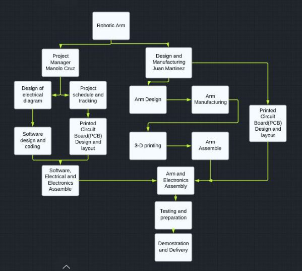
Figure 1. Work Breakdown Structure (WBS)
Product Breakdown Structure (PBS)
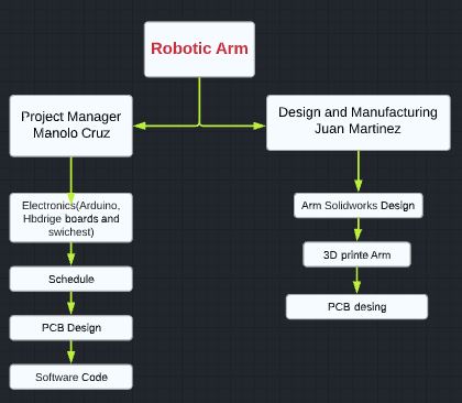
Figure 2. Product Breakdown Structure (PBS)
Cost
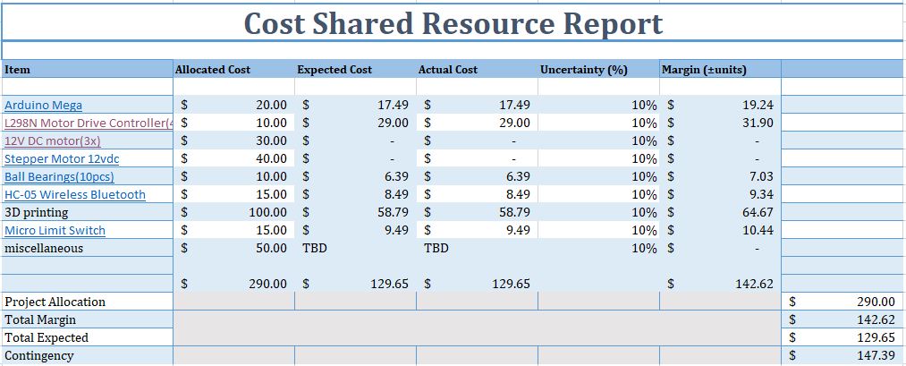
Figure 3. Cost
Schedule
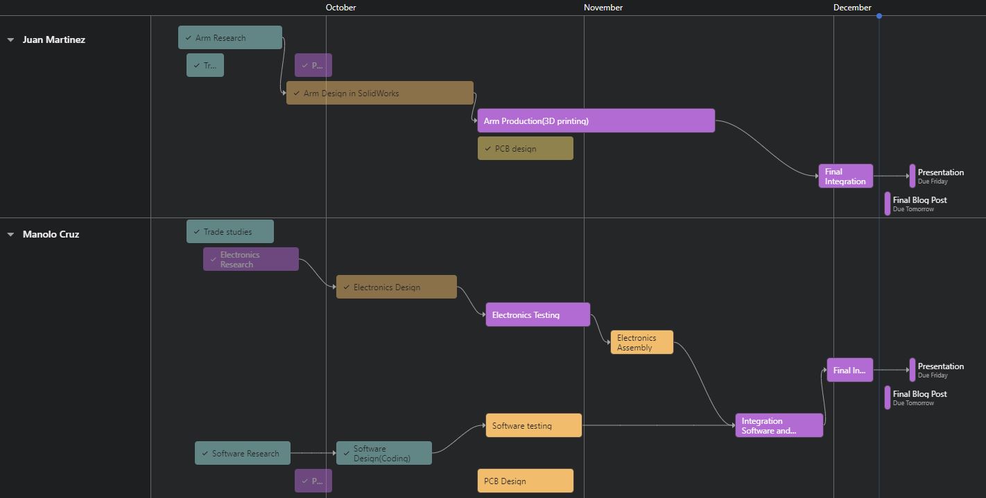
Figure 4. Schedule
Burndown and/or Percent Complete
Figure 5. Burn Down and Progress
Concept and Preliminary Design
The approach was to build a product to be able to grip objects so the team started studying existing robotic arms to learn the layout of the design. After doing a torque analysis the team found the required torque to make the movement of the arm possible after these numbers were verified. The team started looking into which motors could satisfy each set requirement needed.
Literature Review
As the team was researching many different sizes of commercial and DIY projects, most of the DIY projects were built to be relatively small with servo motors. Which would not be viable for the objective, After reviewing more DIY projects we came to more comparable designs that would fit our application while also the amount of customization of the controls were limitless. Commercial robotic arms were more costly due to the amount of precision in their displacements/movements and the requirements of weight and current would not make feasible to build them for our project
Design Innovation
The design was created to accommodate the repurposed motors that were lent to the team provided to our team by the school. The 3D parts were made with the intention to couple the shaft of the motor to the rest of the assembly. We set up a prioritization system to allow only one motor to be activated at any given time, in order to avoid overloading the power supply and comply with the power requirements that were established. This made the design more power efficient.
Conceptual Design / Proposed Solution
The first iteration of our solution was to use two brushless motors and two stepper motors all being controlled by an Arduino Mega. The controls of the system were going to control each motor by the HC05 Bluetooth module which allows us to control the motors through the phone.
The parts for the sections of the robotic arm to be designed on 3D rendering software then printed.
System Design / Final Design and Results
System Block Diagram
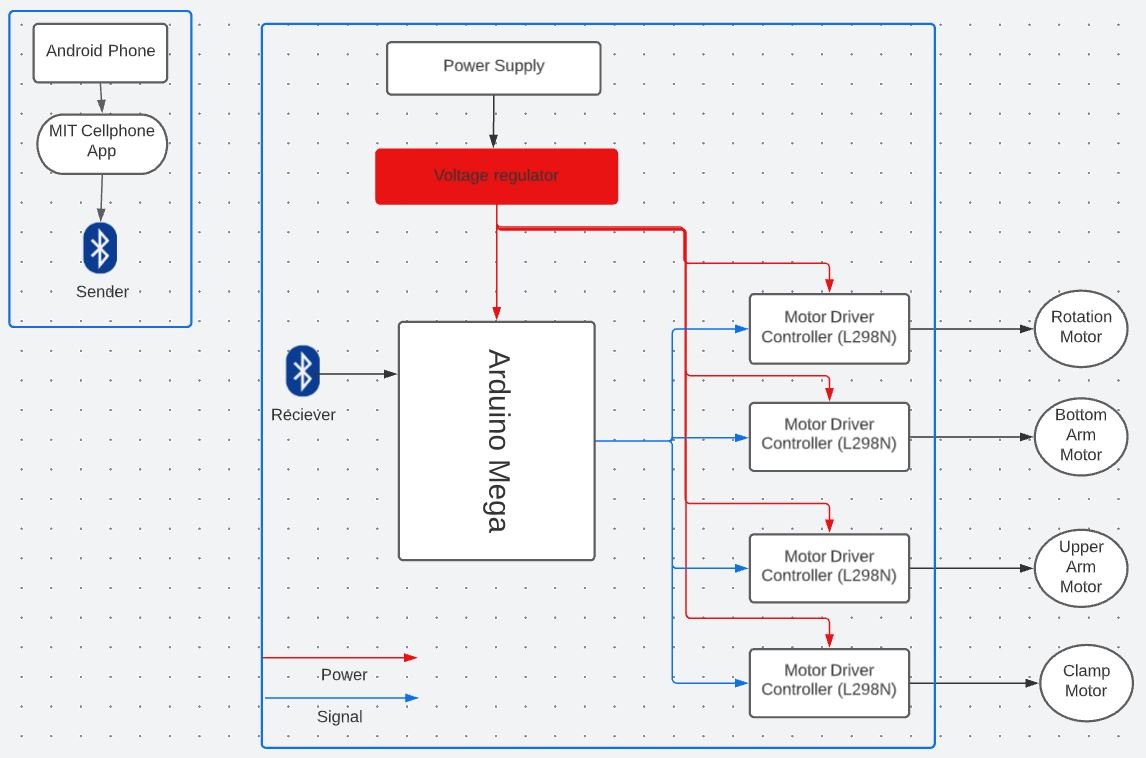
Figure 6. System Diagram Block
Interface Definition
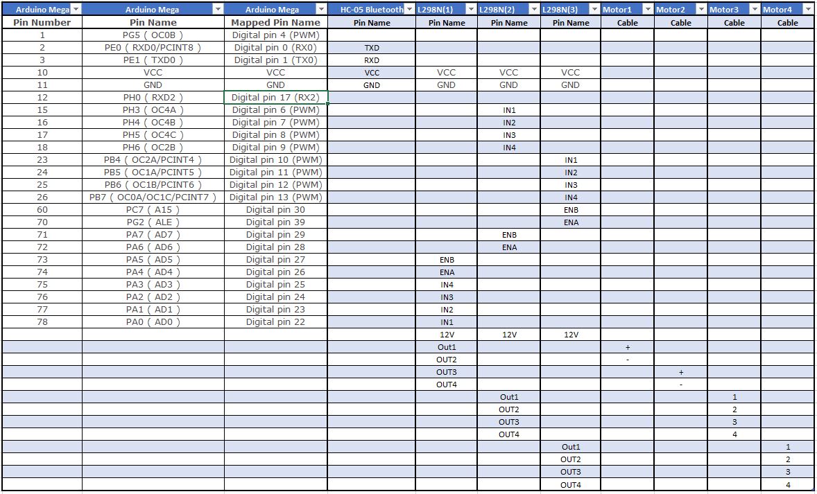
Figure 7. Interface Definition
Our interface matrix was selected to connect an Arduino Mega board to a L298N motor control units to activate and control direction of the motors, by utilizing the digital pins from the Arduino, we are able to send the signal to the controllers that enable parts of the H-bridge and activate the different sections of the bridge and manipulate the direction of the motor. Furthermore, the motor controllers are independently power to supply the corresponding voltage(12V) to the motors, while the controller operate at 5V.
Modeling/Experimental Results
The first task that the team had was to get the dimensions of the output shaft of the motor then integrate this into the design. Which we accomplished by creating gears that would fit onto the shaft while still being able to apply the torque from the shaft of the motor. Since the two brushless motors have the same shaft this just just required a second gear, but the application would be different since a longer distance needed to raise the arm while still connecting the the motor to the link of the arm. The solution that the team found worked in simulation ,but when it was converted to an .stl file created some issues that were pointed out by the Innovation space user interface. It warned that there was a possibility that the piece could break if put under too much stress. The rest of the parts were created following other designs for implementation.
The drwaing paper for the robotic arm are linked below
Mission Command and Control
In order to control the robotic arm, we resource to create an Andriod Cellular Application with the help of MIT App Inventor with the application creator we were able to integrate the application and a Bluetooth module to the Arduino board and being able to control it wirelessly at a distance stablish by the Bluetooth protocols.
The design was indeed simple due the complexity and always it has room to improvement as is shown:
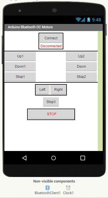
Figure 8 Mission Command and Control
the application was design with the idea of control individual motors with direction and a stop, while having a general stop to pause any movement in the arm.
Electronic Design
PCB Design
Arduino board takes the computing capacity for our program to operate, we create a Printed Circuit Board(PCB) that integrates with Arduino to facilitate the different tasks that the board is being programed to execute. this helping to have a cleaner interaction between all the parts that are integrated in the arm. In particular we design 2 different board due the characteristic of the motors that will be operated.
- Arduino Mega Shield, was created base on the design of the VNH5019 dual motor driver shield for Arduino Uno from Pololu with the exception that our shield can be placed in the Arduino Mega board and with the limitation of space and experience, we only placed one of the VNH5019 compared to the Pololu Shield.
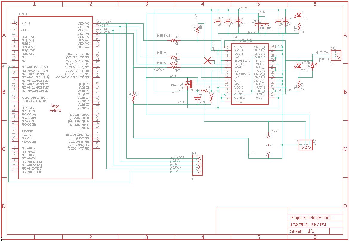 Figure 9 Motor Driver Shield Schematic.
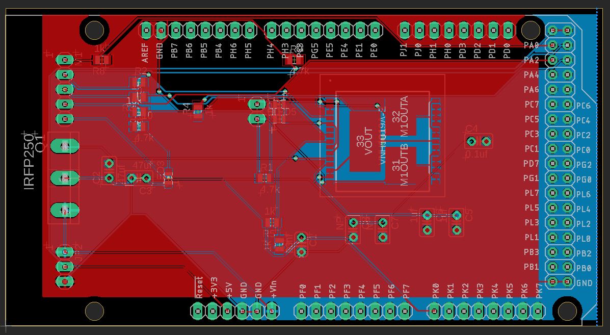
Figure 10 Motor Driver Shield Board.
- L298n H-bridge board was create to complement the necessary motors that will be utilize in robotic arm, this design was obtained from howtomechatronics while the design is simplistic is very important for our project as shown below in the schematic and board.
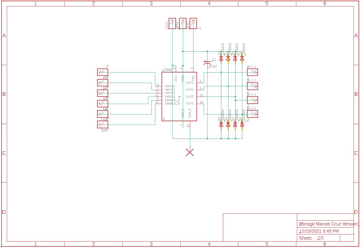
Figure 11 L298n H-bridge Schematic.
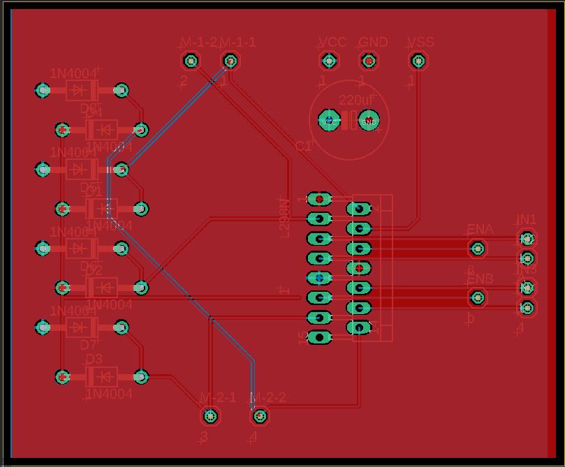
Figure 12 L298n H-bridge Board.
Firmware
Android App
as the interface was stablish, using the MIT app developer tool, we develop the communication within the app to send the proper set of instructions to the Arduino board.
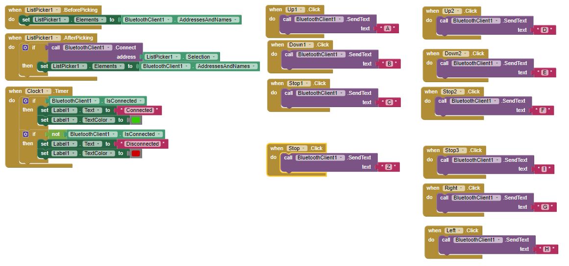
Figure 13. MIT app background code.
The MIT app developer, make it easy for us to stablish communication with the board, since the Bluetooth (BT) protocol is stablish within the app, we just need to stablish the list order that connection is done, as shown in Figure 14. When we select in the application “Connect” the app opens a screen that allow us to select the Bluetooth that we like to communicate with. a list of all possible devices appears, after selecting the proper connection, in our case if HC-05 since that is the BT module. we are able to stablish connection, a green bottom appears that connection was stablish. if connection was not stablish the bottom is red.
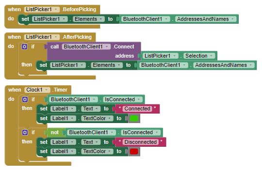
Figure 14. BT connection code.
Once connection is stablish our main bottoms are visible an ready to operate. As show in Figure 15. we have different bottoms that once click they send a letter to the BT and this letter is received in the Arduino board. We have multiple sets of this instructions to control each of the motors in the robotic arm.
Figure 15. Instructional code.
Arduino Code
The code
//CSULB EE400D Class Senior Design Project.//Robotic Arm V1.//Professor: Dr Gary Hill.//Student/Autrhor: Manolo Cruz//We include any library necessary and set up any pin necessary. //this can be changing depending on the complexity of the design and needs.#include//set up motor1 pins int motor1Pin1 = 30; // Pin IN1 on L298N int motor1Pin2 = 31; // Pin IN2 on L298N int enable1Pin = 32; // Pin ENA on L298N //set up motor2 pins int motor2Pin1 = 22; // Pin IN3 on L298N int motor2Pin2 = 23; // Pin IN4 on L298N int enable2Pin = 24; // Pin ENB on L298N int state; int flag=0; //makes sure that the serial only prints once the state int stateStop=0; //set up motor1 pins const int stepsPerRevolution = 20; // steps per revolution // initialize the stepper library on pins 50 through 53: Stepper myStepper(stepsPerRevolution, 50, 51, 52, 53);void setup() {// put your setup code here, to run once:// sets the pins as outputs motor1pinMode(motor1Pin1, OUTPUT);pinMode(motor1Pin2, OUTPUT);pinMode(enable1Pin, OUTPUT);// sets the pins as outputs motor1pinMode(motor2Pin1, OUTPUT);pinMode(motor2Pin2, OUTPUT);pinMode(enable2Pin, OUTPUT);// sets enable1Pin and enable2Pin high so that motor can turn on:digitalWrite(enable1Pin, HIGH);digitalWrite(enable2Pin, HIGH);// set the speed at 60 rpm:myStepper.setSpeed(60);// sets enable1Pin and enable2Pin high so that motor can turn on:digitalWrite(limit1, INPUT);// initialize serial communication at 9600 bits per second:Serial.begin(9600);}void loop(){// put your main code here, to run repeatedly://if some data is sent, reads it and saves in stateif(Serial.available() > 0){state = Serial.read();flag=0;}// if the state is 'A' the DC motor will go UPif (state == 'A') {digitalWrite(motor1Pin1, HIGH);digitalWrite(motor1Pin2, LOW);if(flag == 0){Serial.println("Turn Up");flag=1;}}// if the state is 'B' the motor will Downelse if (state == 'B') {digitalWrite(motor1Pin1, LOW);digitalWrite(motor1Pin2, HIGH);if(flag == 0){Serial.println("Turn Down");flag=1;}}// if the state is 'C' the motor will stopelse if (state == 'C') {digitalWrite(motor1Pin1, LOW);digitalWrite(motor1Pin2, LOW);if(flag == 0){Serial.println("Stop");flag=1;}delay(1500);state=3;stateStop=1;}// if the state is 'D' the DC motor will go UPif (state == 'D') {digitalWrite(motor2Pin1, HIGH);digitalWrite(motor2Pin2, LOW);if(flag == 0){Serial.println("Turn Up");flag=1;}}// if the state is 'E' the motor will Downelse if (state == 'E') {digitalWrite(motor2Pin1, LOW);digitalWrite(motor2Pin2, HIGH);if(flag == 0){Serial.println("Turn Down");flag=1;}}// if the state is 'F' the motor will stopelse if (state == 'F') {digitalWrite(motor2Pin1, LOW);digitalWrite(motor2Pin2, LOW);if(flag == 0){Serial.println("Stop");flag=1;}delay(1500);state=3;stateStop=1;}if (state == 'G'){// step one revolution in one direction:Serial.println("clockwise");myStepper.step(stepsPerRevolution);}else if (state == 'H'){// step one revolution in one direction:Serial.println("counterclockwise");myStepper.step(stepsPerRevolution);}}