Top Shield PCB Debugging
Introduction
The Top Shield for MarioBot provides 3.7V to 12V boost, load switching, and IR receiver capabilities. Unfortunately, the Top Shield did not work and ended up shorting and melting the wires. This post will outline the problems encountered and some potential solutions.
Debugging:
Before powering on the TopShield, I tested continuity using a multimeter on every trace and component. This is where I encountered the following problems:
Problem 1: MOSFET
The first problem I encountered while debugging the Top Shield is that I noticed the MOSFET (CSD17308Q3) had continuity between source and drain. As the package of the MOSFET did not have exposed pads, my first thought was that it was solder bridged underneath. After reflowing and checking the datasheet, I observed that the drain was connected to the wrong pad.
I blindly trusted the PCB Footprint of the MOSFET that I downloaded from SnapEDA. This footprint was not physically wrong, but it labeled the pins differently than our schematic symbol for the MOSFET.
I labeled the schematic symbol of the MOSFET as 1: Gate 2: Drain 3: Source.

CDS17308Q3 MOSFET Schematic Symbol
But the PCB Footprint had 1 as Gate, 2-4 as Source, and 5-8 as Drain.
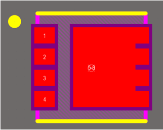
CDS17308Q3 MOSFET PCB Footprint
Because this was a labeling mistake, Altium did not catch it during the ERC/DRC. So, I fixed this on the PCB, but it still had a short somewhere else.
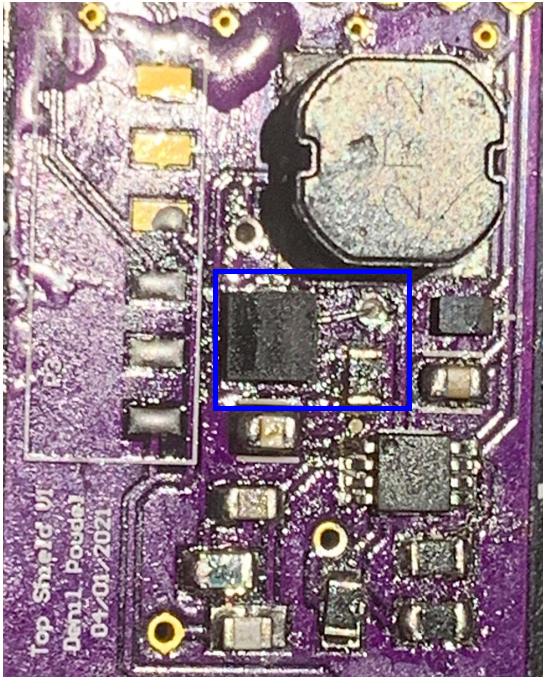
Top Shield PCB w/ Blue Box Around MOSFET
Problem 2: 5mOhm Resistor
The second problem I encountered was similar to the first problem. While checking continuity I noticed that both sides of the 5mOhm Sense Resistor were continuous. Again, thinking it was a solder bridge, I reflowed it. While I was checking the pads on the resistor, I noticed that the pad shapes are different from the PCB footprint. The resistors’ physical pad layout does not match the footprint, it actually ends up bridging the pads together, so I fixed it by soldering wires to it.
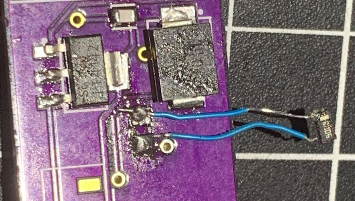 Top Shield Back Side w/ jumper wires for 5mOhm resistor
Problem 3: Short Between +RAW & GND
After fixing the 5mOhm resistor short, I checked continuity on all components and traces again. I especially checked the +RAW and GND connections and vias. I used jumper cables to connect the 3DoT +RAW and +GND to the top shield. The wires started smoking. I unplugged it and tested continuity again and it was fine, and then I tried it again with different wires, but then the same thing happened, and the wires melted. I tried debugging more, but I could not find out the problem and I did not risk turning it on again.
Potential Issues/Solutions:
I went through the Top Shield Altium Schematic and it matches the TI WEBench Power Supply design schematic that the team based our boost converter on. Although, I did some part substitutions from the TI design because they were using 0402 and 0603 and I wanted it to be all 0805s. These substitutions could potentially have contributed to the short. Furthermore, I reflowed a lot of components, the long heat exposure may have internally damaged some components.
Another thing I did not try was feeling for which component got hot. For the future, I would use a variable power supply, set the voltage low, and observe if any components are warmer than the rest. This would give a good indication of the area of the short.
Conclusion
In conclusion, I’m not sure of the root cause of the problem for the meltdown. There were some silly mistakes with the PCB footprints that were fixed, but they could have contributed to the problem. One of the most valuable lessons from this is to always double-check 3rd party schematic symbols and PCB footprints against the datasheet and against the physical part itself.