Fall 2021 Com Bot Generation 1 Final Blog Post
By: Andres Barboza (Project Manager), Sam Kisaka (Mission, Systems, and Test Engineer), Harrison Sanin (Electronics and Control Engineer)
Table of Contents
Executive Summary
The goal of the project is to design a Companion or Communication Robot (Com Bot) that will lead the robot dog along its journey and be controlled wirelessly. Inspired by battery-powered vehicles known as Power Wheels, the vehicle has been further developed to utilize a telemetry module and provide and receive power from subsystems such as a Solar Tracker and Camera Stabilizers. Com Bot is designed to include an Arduino Leonardo to manage all of Com Bot’s features. Com Bot includes two 18V 4Ah batteries, two 12V gear motors, two BTS7960 motor drivers to control the motors of the Com Bot, an actuator for steering, and an HM-10 Bluetooth Module to communicate with the Com Bot. The proof of concept will be verified by traversing Com Bot through the Japanese Garden.
Program and Project Objectives
Program/Project Objectives
The Robot Company has tasked our team to design a Communication Robot (Com Bot) that will be a guide for the Go1 Pro robot dog to follow. A series of tasks and challenges will be faced during the expedition that will be done at the Japanese Garden. The Com Bot will have a designated starting position and will be operated by a controller to navigate through sidewalks, streets, and offroad. The Com Bot will support the use of camera stabilizers to allow for a live view and solar trackers for a backup battery supply.
Mission Profile
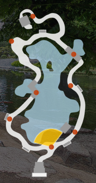
Figure 1.1 Japanese Garden Path
Com Bot will be controlled remotely to navigate through the Japanese Garden consisting of sidewalks, streets, and dirt paths with tree roots. The Com Bot team will work with the solar tracker and camera stabilization teams to ensure that their projects are compatible with and can be connected to the Com Bot. Com Bot will be tested and mounted with stabilized cameras and a solar tracker throughout the duration of the test.
Project Features
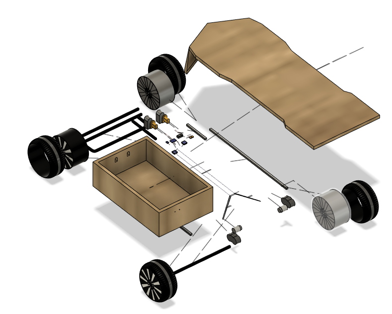
Figure 1.2 Com Bot Exploded View
Com Bot will feature a wooden chassis with an aluminum frame mounted on top of the front and rear axles of four wheels with two 12V gear motors attached to the rear wheels. The inside of the compartment box will contain the electronics such as the two drill batteries, Arduino Leonardo, two BTS7960 motor drivers, and an HM-10 Bluetooth Module along with wires and connectors. The connectors are two XT30U female connectors to provide and receive power from the Solar Panel and Camera Stabilization groups who will provide the male connectors and be able to place their electronics inside the compartment box as well after having placed their mounts on top of the Com Bot.
Requirements
The system and subsystems of Com Bot will be designed, built, and tested in compliance with the engineering standards and constraints as well as the Level 1 and Level 2 requirements tailored to Com Bot.
Engineering Standards and Constraints
Com Bot shall be constrained to a Cost to not exceed $500.
Com Bot’s schedule shall be constrained to a completion date of Tuesday, December 14, 2021. Project completion includes documentation and materials purchased by or loaned to the project.
Com Bot’s wiring Aesthetics shall be nice and clean with the usage of terminal blocks, 100 mil contact pins, and headers, 2.0mm PH series JST connectors, and barrel connectors. Handling Precaution for Terminal and Connector will be in compliance with JST documentation.
Com Bot shall be designed in such a way that there are no dangling or exposed wires. Connectors will be used between all electronic and electromechanical components. Jumper wires will not be used, ribbon cables are preferred;
Back of the envelope calculations and experiments shall be conducted to set the diameter of power-carrying wires. Follow the American Wire Gauge (AWG) standard when defining the diameter of power-carrying wires. This work is to be completed and documented by the CDR. All Safety regulations as defined in Section 4.3 Hazards and Failure Analysis of this document shall apply.
Com Bot software will be written in the Arduino De facto Standard scripting language and/or using the GCC C++ programming language, which is implements the ISO C++ standard (ISO/IEC 14882:1998) published in 1998, and the 2011 and 2014 revisions. Required exceptions to this standard can be found here.
Maintainability: Disassemble and Reassemble of Com Bot shall be constrained to less than 20 minutes (10 + 10 minutes).
Usability of the Com Bot shall be enhanced by adding autonomous functions and/or by use of the Arxterra phone application as dictated by the assigned mission.
Applicable Engineering Standards
- Com Bot shall comply with IEEE 29148-2018 – ISO/IEC/IEEE Approved Draft International Standard – Systems and Software Engineering — Life Cycle Processes –Requirements Engineering.
- Com Bot shall comply with NASA/SP-2007-6105 Rev1 – Systems Engineering Handbook.
- Com Bot shall comply with Bluetooth Special Interest Group (SIG) Standard (supersedes IEEE 802.15.1)
- Com Bot shall comply with C++ standards (ISO/IEC 14882:1998).
- Com Bot shall comply with Federal Communications Commission (FCC) Relevant standards for a product implementing a 2.4GHz radio, FCC Intentional Radiators (Radio) Part 15C, and Unintentional Radiators FCC Part 15B for CPU, memories, etc.
- Com Bot shall comply with NXP Semiconductor, UM10204, I2C-bus specification, and user manual.
- Com Bot shall comply with ATmega16U4/ATmega32U4, 8-bit Microcontroller with 16/32K bytes of ISP Flash and USB Controller datasheet section datasheet, Section 18, USART.
- Com Bot shall comply with USB 2.0 Specification released on April 27, 2000, usb_20_20180904.zip.
Environmental, Health, and Safety (EH&S) Standards
- Com Bot shall comply with CSULB College of Engineering (COE) Safety Resources.
- Com Bot shall comply with CSULB Environmental Health & Safety (EH&S).
- Com Bot shall comply with IEEE National Electrical Safety Code (NESC).
- Com Bot shall comply with NCEES Fundamental Handbook (FE) Reference Handbook.
- Com Bot shall comply with ASTM F963-17, The Standard Consumer Safety Specification for Toy Safety.
Standards Development Organizations
A standard is a document that defines the characteristics of a product, process, or service, such as dimensions, safety aspects, and performance requirements.
- ASTM (American Society for Testing and Materials)
- IEEE (Institute of Electrical and Electronics Engineers)
- ASME (The American Society of Mechanical Engineers)
- ANSI (American National Standards Institute)
- NASA Standards
- ISO (International Organization for Standardization)
- NIOSH (National Institute for Occupational Safety and Health)
Program/Project Level 1 Requirements
L1.1 Com Bot shall act as a companion for the Go1 Pro Robot Dog to follow beside or behind.
- Criteria: ComBot will have reflector strips to assist the robot dog in recognizing and following ComBot.
L1.2 Com Bot shall match or exceed the speed of the Robot Dog of 1.85 m/s.
- This requirement will be verified by using a speedometer app to verify that Com Bot reaches 1.85 m/s (4.14 mph).
L1.3 Com Bot shall support a payload mass of greater than 5.26 kg.
- Criteria: The Com Bot will carry a payload weight exceeding 5.26kg while moving at a speed at or greater than 1.85 m/s.
L1.4 Com Bot shall be easily configurable based on Internet sources.
- Criteria: There will be no wires from the controlling device to the Com Bot.
L1.5 Com Bot will be a vehicle.
- Criteria: The Com Bot will move along the designated path described in the mission profile without needing any external force to help it along said path.
L1.6 Com Bot shall be able to go on sidewalks, streets, and offroad.
- This requirement will be verified by successfully navigating the Com Bot over and through the types of terrain listed above.
L1.7 Com Bot will carry a solar tracker and one stabilized camera.
- Criteria: This requirement will be verified by mounting a solar tracker and one stabilized camera on top of Com Bot
L1.8 Com Bot batteries will be rechargeable.
- This requirement will be verified by demonstrating one charging cycle on the day of the final.
L1.9 Com Bot power shall be compatible with the solar panel and camera team systems.
- Criteria: Once requirement L1.7 is successfully completed, this requirement will be verified by connecting the other systems to Com Bot’s power and communication interfaces.
L1.10 Com Bot should have a runtime of 1 hour.
- This requirement will be verified by measuring the current draw of each of the components on the day of the final and calculating the total runtime based on the amps used and our 8 Ah supply.
L1.11 Each team member of Com Bot other than the Project Manager shall design a custom PCB.
- Criteria: This requirement will be verified by presenting custom PCBs.
System/Subsystem/Specifications Level 2 Requirements
L2.1 – To fulfill requirement L1.1, Com Bot should guide Robot Dog around the Japanese Garden.
L2.2 – To fulfill requirement L1.2, Com Bot will have 11-inch wheels.
L2.3 – To fulfill requirements L1.2 and L1.5, Com Bot will have 2 gear motors for the two back wheels.
L2.4 – To fulfill requirement L1.3, Com Bot will have a wooden chassis with an aluminum frame.
L2.5 – To fulfill requirement L1.4, Com Bot wheel motors and communications shall be controlled by an Arduino Uno microcontroller.
L2.6 – To fulfill requirement L1.4, the Com Bot microcontroller will be controlled wirelessly via communication between an HM-10 Bluetooth module and the iPhone application “Dabble”
L2.7 – To fulfill requirements L1.5, Com Bot will have size dimensions that do not exceed a length of 44.25 inches, a width of 30 inches, and a height of 13.625 inches.
L2.8 – To fulfill requirement L1.5, Com Bot will use an actuator to steer the vehicle.
L2.9 – To fulfill requirements L1.6, Com Bot’s wheels will have plastic tires mounted with gear motors on the rear axles.
L2.10 – To fulfill requirement L1.7, Com Bot shall provide mounting space to carry a solar panel and two camera stabilizers.
L2.11 To fulfill requirements L1.8, Com Bot should have a kill switch located outside the compartment box in the case of a power mishap and a kill switch for the microcontroller and battery.
L2.12 – To fulfill requirements L1.8, Com Bot should be able to provide power to the stabilized cameras and receive power from the solar panel.
L2.13 – To fulfill requirements L1.9, Com Bot will use two XT30U connectors to provide and receive power.
L2.14 – To fulfill requirement L1.10, Com Bot will have two 18V and 4Ah batteries.
L2.15 – To fulfill requirement L1.11, the PCB designs will be a motor speed controller and a motor driver.
Allocated Requirements / System Resource Reports
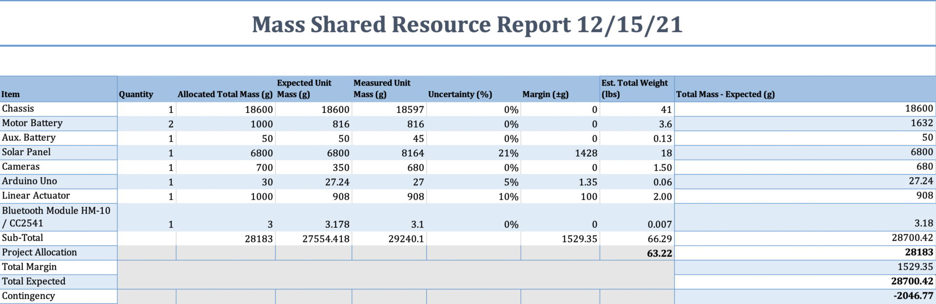
Figure 2.1 Mass Report
The mass allocation report consists of each component that involves Com Bot without Solar Tracker and Camera Stabilization projects being mounted. A sub-total weight of 66.29 lbs will allow for a greater center of gravity and support the weight of Solar Tracker and Camera Stabilization projects.
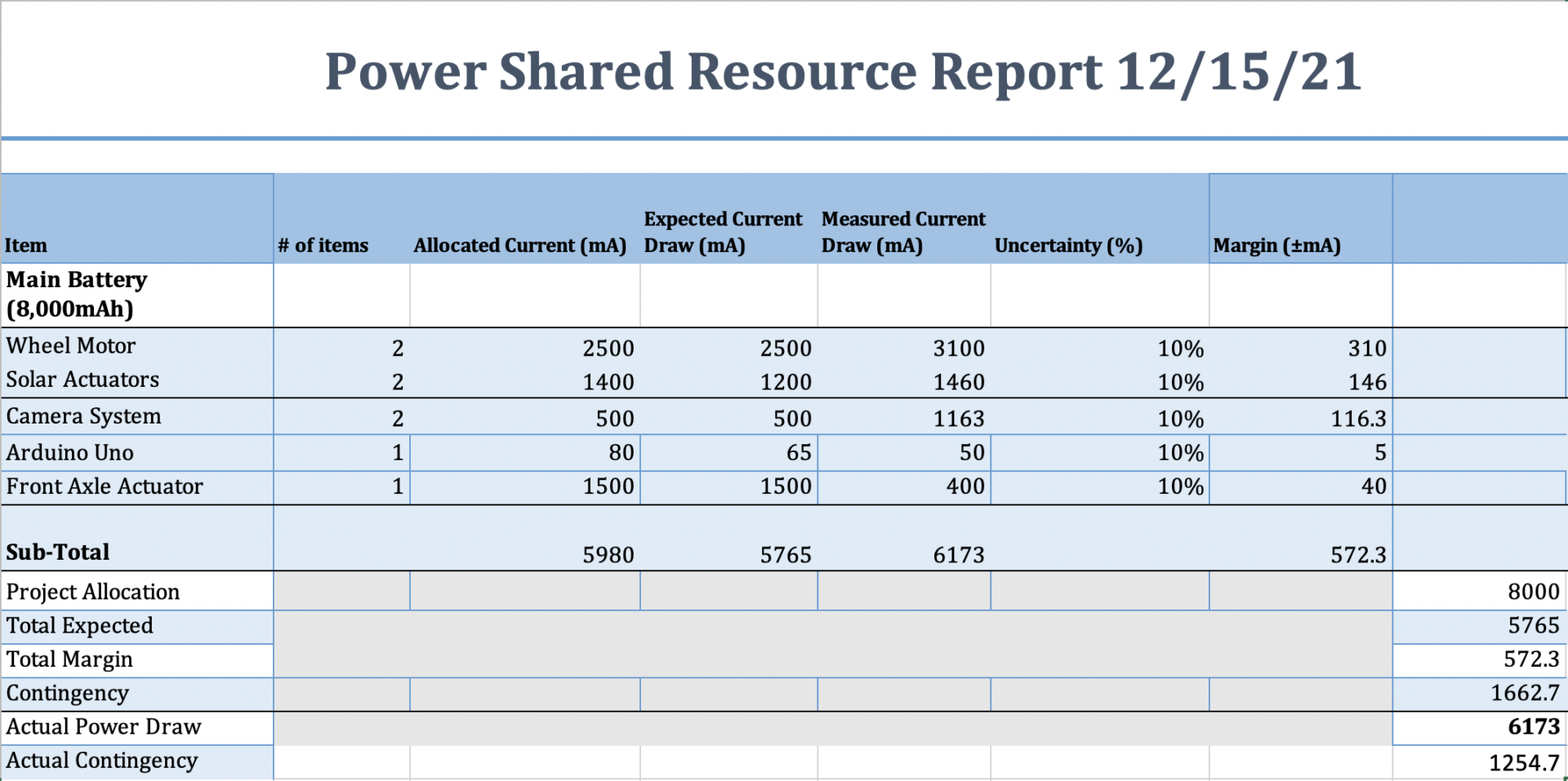
Figure 2.2 Power Report
The power allocation report consists of the current draw from each source that requires power. Placing two 18V 4Ah drill batteries in parallel will allow a maximum of 8Ah which is plentiful to supply the expected allocated current of 5,980 mA or 5.98 A.
Project Report
The following section contains the layout of the Work Breakdown Structure and the Product Breakdown Structure. In addition, the cost and schedule of distributed tasks for the Com Bot team that the project manager planned out are included.
Project WBS and PBS
Work Breakdown Structure
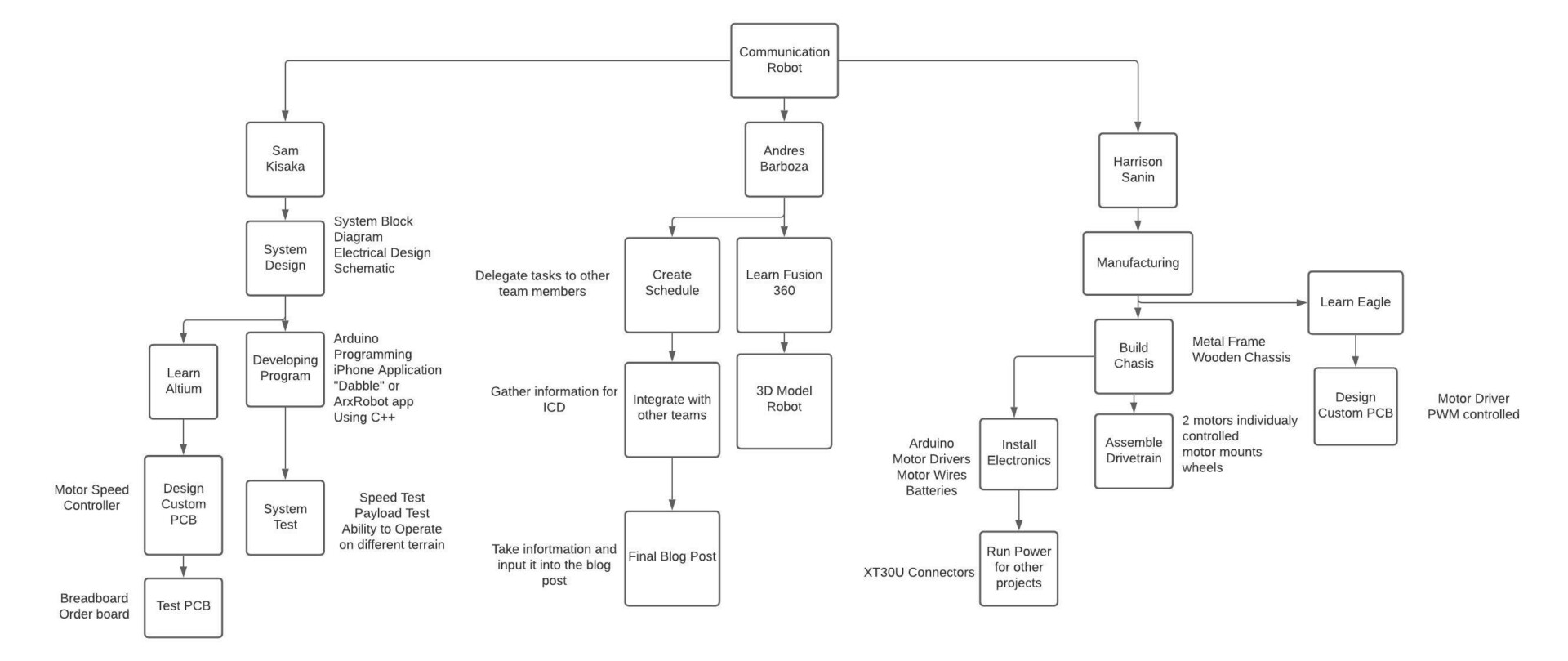
Figure 3.1 Work Breakdown Structure (WBS)
Shown above in Figure 3.1 is the Work Breakdown Structure. Each team member was responsible for a group of different tasks. As a whole, the project was split into manufacturing, system design, and overall project integration. In order to complete the given objective team members often worked together to complete some tasks on different branches of the product as a team.
Product Breakdown Structure
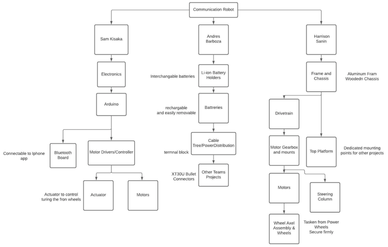
Figure 3.2 Product Breakdown Structure (PBS)
Depicted above in Figure 3.2 is the Product Breakdown Structure. The product may be sectioned off into electronics, power distribution, and the overall chassis. The product was broken down in such a way that the process of developing and building a working Com Bot could be achieved by completing the parts of the product in the sequence above.
Cost
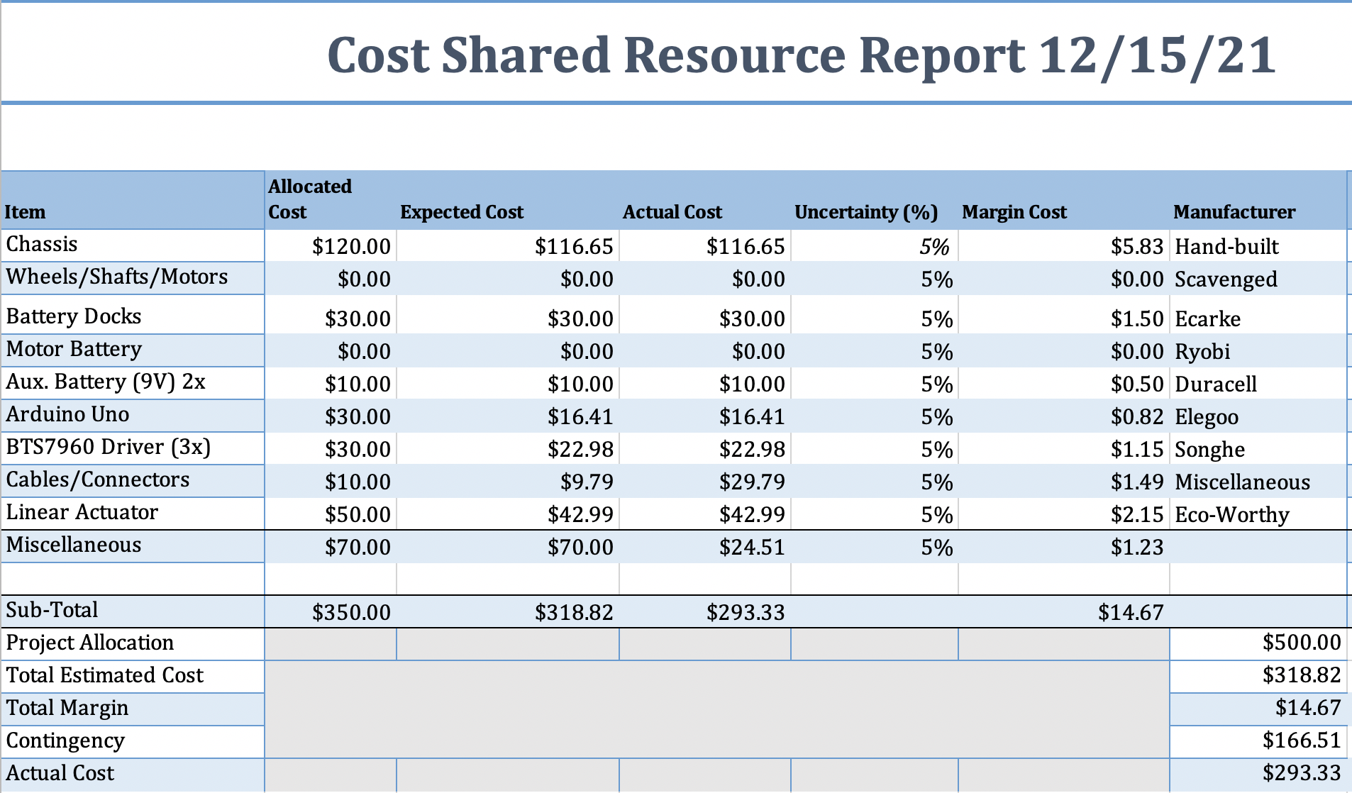
Figure 3.3 Cost Report
With a project allocation budget of $500, the Com Bot team was able to minimize costs to an allocated cost of $300 as we were able to strip down a used power vehicle for its wheels, gear motors, and axles. After having purchased all components to create Com Bot, the Com Bot team was left with a large surplus to make further improvements if needed.
Schedule

Figure 3.4 Com Bot Schedule
Com Bot’s Schedule consists of three critical paths which include the main Com Bot Build, Commutator Noise Sensorless Encoding, and the Back EMF Sensorless Encoding. A few tasks were delayed in the later stages of Com Bot due to some communication issues with the Arduino and Com Bot.
Burndown and/or Percent Complete

Figure 3.5 Com Bot Burndown and/or Percent Complete
Com Bot is on track to be completed by December 14, 2021, despite the software portion taking longer for us to complete causing delays in testing for Com Bot. Although insufficient testing may result in issues beyond our demonstration date.
Concept and Preliminary Design
The following section displays how the research we have performed has developed the proposed designs of Com Bot ultimately agreeing to the final adaptation of the first generation of Com Bot.
Literature Review
Each engineer on the Com Bot team performed research to find the best solutions for our mechanical design such as the chassis and frame and the electrical and power design to receive and provide power to other projects. Additional research was performed to determine the best method of receiving and transmitting information to the Com Bot. With the research performed, the Com Bot team mutually decided on the components that would essentially convert a power-wheeled vehicle into a wirelessly controlled Com Bot.
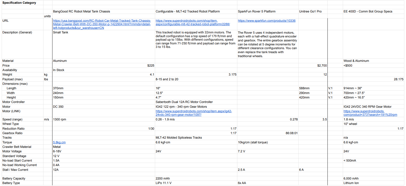
Figure 4.1 Com Bot Spreadsheet
With the information found, we found it difficult to create a Com Bot from scratch within our budget, therefore causing the Com Bot team to look for cheaper yet capable alternatives to meet the requirements of the Com Bot. Thus making the Com Bot team look for DIY projects that would allow us to achieve our goals.
Design Innovation
The Com Bot design was inspired by an individual who converts and upgrades power wheels into radio-controlled vehicles. From the research performed on the individual’s work, the Com Bot team analyzed what was needed to be done to create a successful Com Bot. By taking the wheels and axles of a power wheeled vehicle, we were able to design our own frame and chassis that would allow Com Bot to support the payload of additional projects that will function with Com Bot.
Conceptual Design / Proposed Solution
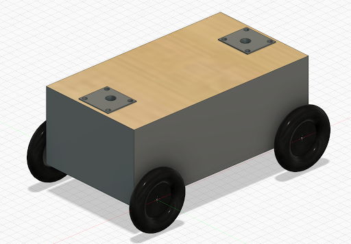
Figure 4.2 Initial Com Bot Design
After having created an initial design as seen in Figure 4.2, the Com Bot team needed to reduce costs as creating a Com Bot from scratch was out of budget. After multiple designs and solutions were proposed and the Com Bot team mutually agreed on the solution of stripping a power wheeled vehicle for its wheels, motors, and axles. After having designed the chassis and frame for Com Bot the solution proposed was to incorporate an Arduino Leonardo using an HM-10 with two BTS7960 motor drivers which are H-bridges thus allowing for a motor driver to go each motor allowing for easier control for steering our Com Bot.
System Design / Final Design and Results
System Block Diagram

Figure 5.1 System Block Diagram
Our system design is simple, yet it takes a lot of subsystems and integrates them into one cohesive unit. At its core, our system is controlled by the Arduino Uno. This microcontroller is able to receive inputs wirelessly courtesy of our HM-10 Bluetooth module. Those inputs get sent out of the Arduino to our three motor drivers, each of which is controlled by a pair of BTS7960B integrated circuits. Two of the drivers are controlling the back wheels, while the third driver is responsible for turning the front wheels left and right. The motors themselves are powered by 2 18V 4Ah drill batteries, but the BTS7960B IC’s are being powered by the Arduino’s onboard 5V supply. We have the two 18V batteries connected to a terminal block in parallel, which provides us with a total of 18V and 8Ah to the Com Bot and its subsystems. From the battery’s terminal block, we are running power to the back wheel motors, the camera team’s stabilization system, the solar panel team’s actuators, and a buck converter that takes the voltage down to 12V for the front axle’s actuator. Our Arduino Uno and Solar Tracking’s Arduino Micro are powered from a separate 9V power supply that will not blow their circuitry. The final part of the design is the control interface. For this final iteration of Com Bot generation 1, we have chosen to stick with the iPhone application ‘Dabble’. We made this decision after many hours spent trying, unsuccessfully, to get the ArxRobot application to work with our iPhones.
Interface Definition
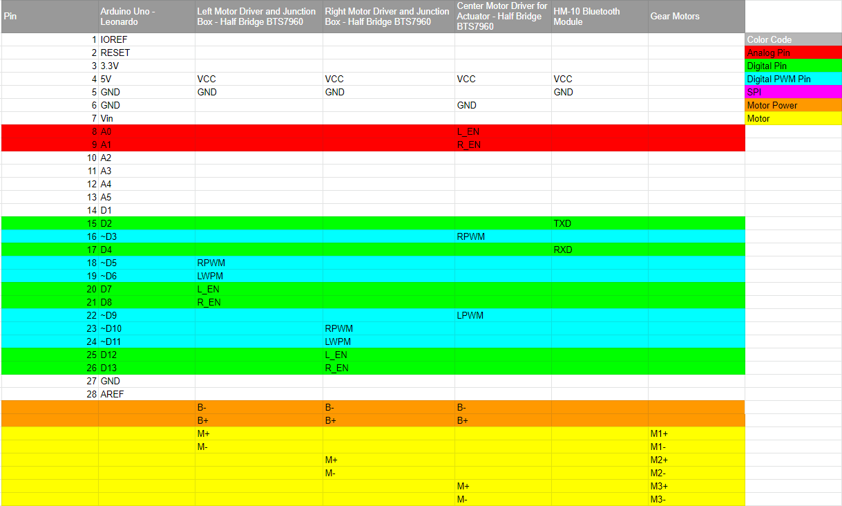
Figure 5.2 Interface Matrix
As shown in Figure 5.2, the Arduino Uno communicates with the BTS7960 Motor Drivers and HM-10 Bluetooth Module. Meanwhile, the Motor Drivers junction boxes communicate with their respective gear motors. The Arduino Uno uses pin D2 to connect to pin TXD for a serial connection to the HM-10 Bluetooth Module while the Arduino pin D4 connects to pin RXD to link logically to the BLE service and connection of the HM-10 Bluetooth Module. The center motor drive will utilize an actuator with Arduino pins A0 & A1 going to L_EN & R_EN while pins ~D3 & ~D9 go to RWPM and LWPM. The Arduino Uno is utilizing four Digital PWM pins, where pins ~D5 and ~D6 will go to the left motor driver and pins ~D10 and ~D11 will go to the right motor driver. An additional four Digital pins will be utilized to activate the RWPM and LWPM of each motor driver by having Arduino pins D7 & D8 go to L_EN & R_EN of the Left Motor Driver while Arduino pins D12 & D13 go to L_EN & R_EN of the Right Motor Driver. Both motor drivers have linked pins B- together and B+ together to power their batteries. Pins M- and M+ of the left motor driver will go to pins of M1- and M1+ to power the gear motor while pins M- and M+ of the right motor driver will go to pins of M2- and M2+ to power the other gear motor.
Modeling/Experimental Results
Full-Scale Prototype
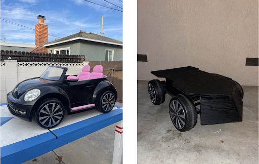
Figure 6.1 Com Bot Assembly
The overall design of the Com Bot went through multiple design changes, based on time and available parts. As opposed to building an entire chassis and frame from scratch, parts were scrapped from Power Wheels which included wheels, wheel axles, gearboxes, and motors. The way they were attached and configured was altered until the final design was agreed upon and could be built as the final iteration.
Scale Model
When trying to figure out how to best write the code for controlling the motor drivers, a physical breadboard model was constructed of a similar motor driver to fully understand how the drivers worked. This breadboard was also used to create the custom motor driver PCB that uses a 555 timer and PWM to control the speed of the motor. The experimental results were successful, but for the finished ComBot, we ended up going with a different, off-the-shelf driver because we needed a driver that could handle the high current draw from ComBot.
Physical Model

Figure 6.2 Miniature Com Bot
A scaled-down 4 motor “robot” was used as a smaller version of the com bot in order to test if the code was functioning correctly before the full-scale model was completed. This was made easy with an onboard Arduino and motors already connected to a PWM motor controller.
Analytical Model/Back of the Envelope Calculations
Torque Needed to Move at a Speed of 1.85m/s
Back-of-the-envelope calculations were done with an online robot speed calculator. It was determined that the motor needed to spin at a speed of 340 rpm in order to reach the desired output speed.
Trade-off Study
Reviewing the cost of the two batteries the li-ion batteries are generally more expensive, however, they are much lighter in comparison. When comparing the weight of the 10lb 12v 12Ah lead-acid battery to the 3.6lb 18v 8Ah li-ion batteries chosen, the li-ion delivered the same amount of power at just shy of a third of the weight. An added benefit of the Li-ion is faster charging and interchangeability.
Mission Command and Control
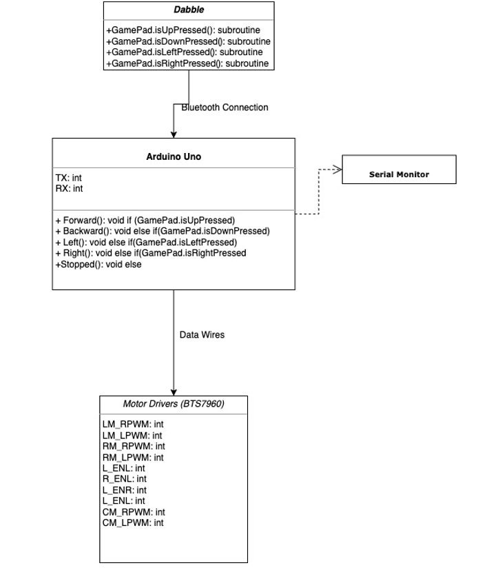
Figure 7.1 UML Diagram
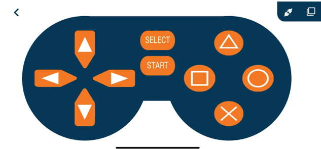
Figure 7.2 View of Dabble UI
For mission command and control, the user of ComBot currently has access to four D-pad buttons with which to control the direction in which the robot moves. When the user presses up on the D-pad, it sends a signal to the onboard HM-10 Bluetooth module which enables the GamePad.isUpPressed function to execute. This function enables the two back wheel motors to maneuver the ComBot in a forward direction at a speed predetermined by our code. If the left D-pad button is triggered by the user, the GamePad.isLeftPressed function executes, which causes the back motors to slow their forward speed while the front actuator retracts to turn the wheels to the left. For each data input from the Dabble application, the code will print out the command that has been pressed to the Serial Monitor in the Arduino IDE software. Time permitting, we may add other functionality to the other buttons available to us in Dabble.
Electronic Design
PCB Design
PCB Schematic
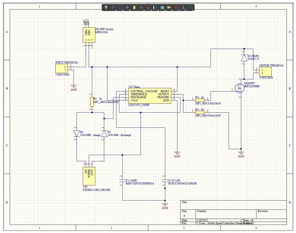
Figure 8.1 Schematic of Motor Speed Controller Circuit
For the custom PCB design requirement of this course, Sam chose to design a Motor Speed Controller. For this design, he chose to go with a 555 Timer IC and MOSFET for the heart of the speed controller. The voltage applied to the gate pin of the MOSFET is controlled using Pulse Width Modulation (PWM) from the 555 timer. PWM is simply a square wave signal sent from the 555 timer. The voltage is on when the pulse is high, and the voltage is off when the pulse is low. The MOSFET receiving this signal will only “see” the average value of the voltage, so the longer the pulse is high, the higher the average voltage experienced by the FET at the gate pin. Adjusting the average voltage going to the gate pin allows us to control the voltage being applied to the motor, and thus, its speed.
Physical Breadboard
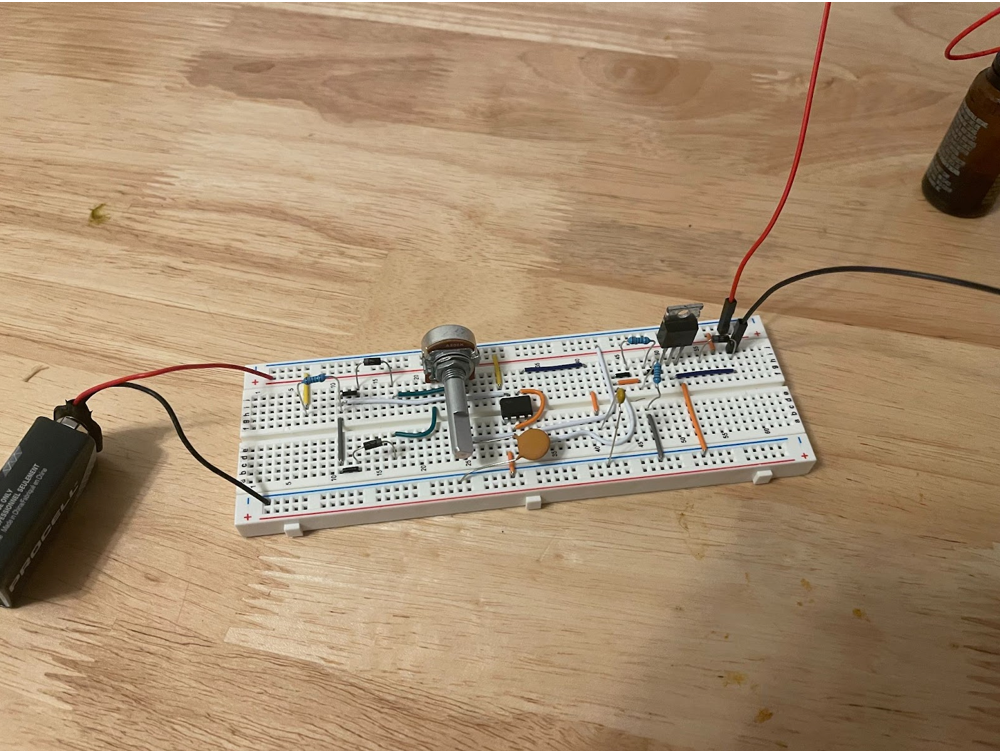
Figure 8.2 Physical Breadboard of Motor Speed Controller Circuit
Copying the schematic in Figure 8.1, a working version of the motor speed controller was successfully tested with the components used in the schematic design. The circuit works as designed, and the motor speed increased as the potentiometer is turned clockwise, and decreases as the pot is turned counterclockwise.
Motor Speed Controller PCB (2D)
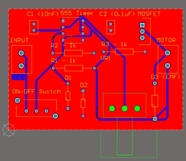
Figure 8.3 Motor Speed Controller PCB Top Layer
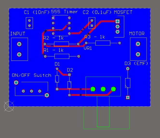
Figure 8.4 Motor Speed Controller PCB Bottom Layer
As shown in Figures 8.3 and 8.4, this is the finished PCB design layout made with Altium Designer. There is a poured layer for ground in between the top and bottom layers of the PCB, and all routing was done such that the wires do not cross one another on the same layer.
Motor Speed Controller PCB
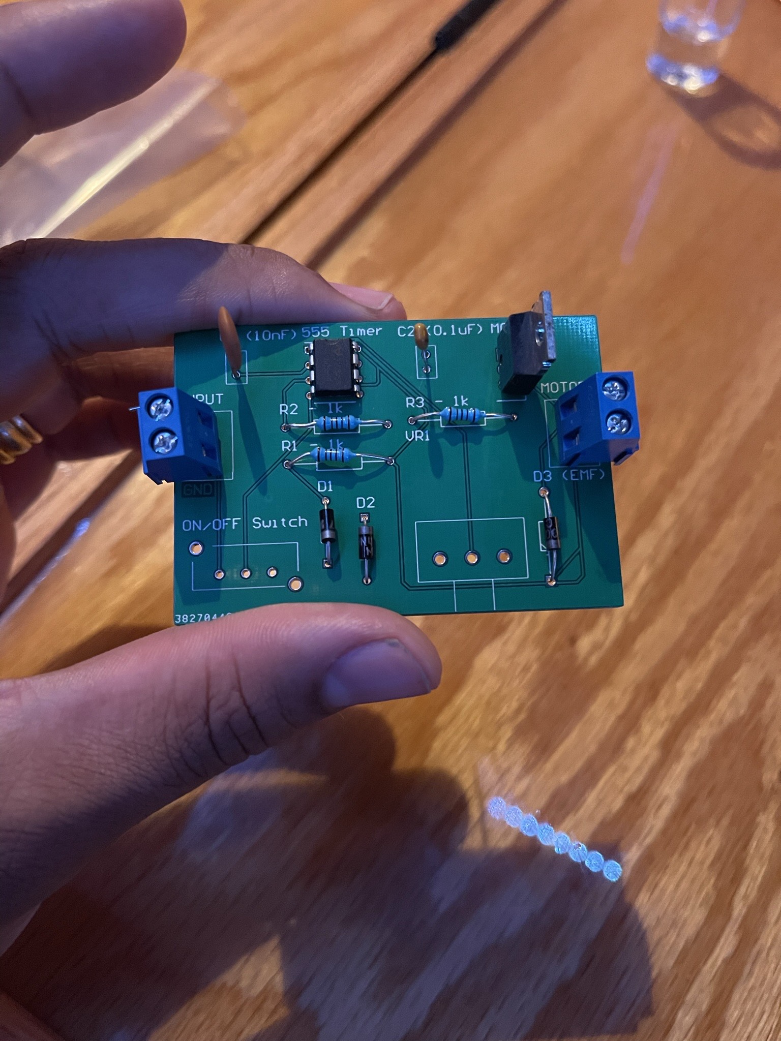
Figure 8.5 Motor Speed Controller PCB
For ComBot, our speed is controlled via PWM in the Arduino code, but we thought it might be a cool idea to have an external speed controller as shown in Figure 8.5, that would control the voltage going to the motors via a physical potentiometer. This way, we could limit ComBot’s speed from the outside of the chassis instead of uploading new code every time we wanted a different speed setting. We did not end up using this on the day of the final as we came up with a way to control ComBot sufficiently using two speeds.
Firmware
For our firmware, we had a lot of trouble trying to get the iPhone app ArxRobot and its corresponding libraries to work with our Leonardo, so we moved on to our plan B of using Dabble to remotely control ComBot. Using the included library, we were successful in sending a signal from an iPhone with a gamepad UI to an Arduino Uno that has been outfitted with an HM-10 Bluetooth module.
C++ Code
/* ComBot Movement Code - Dabble Edition
 *  Author: Sam Kisaka
 *  CSULB EE400D - Fall 2021
 */
#define CUSTOM_SETTINGS
#define INCLUDE_GAMEPAD_MODULE
We are still working out the kinks in the code that controls the turning of the Com bot and the movement of the linear actuator, but what we have so far can be seen in the code below. The comments in the code clearly explain what the code is doing, but one thing to note is that the BTS7960 drivers must have both enable pins (L_ENL, R_ENL) pulled high in order for any movement to occur in the motor. The direction and speed are controlled from the left and right PWM pins.
int TX = 2;       // Transmit pin for HM-10
int RX = 4;       // Receive pin for HM-10
int LM_RPWM = 5;  // Left Motor Forward PWM pin
int LM_LPWM = 6;  // Left Motor Reverse PWM pin
int L_ENL = 7;    // Left Motor Reverse Enable pin
int R_ENL = 8;    // Left Motor Forward Enable pin
int RM_RPWM = 10; // Right Motor Forard PWM pin
int RM_LPWM = 11; // Right Motor Reverse PWM pin
int L_ENR = 12;   // Right Motor Reverse Enable pin
int R_ENR = 13;   // Right Motor Forward Enable pin

int Speed = 0;    // Initialize variable for the speed of the motor (0-255);
int CM_RPWM = 3;  // Retract Actuator Pin
int CM_LPWM = 9;  // Extend Actuator Pin
int L_ENC = A0;   // Left enable
int R_ENC = A1;   // Right enable

void setup()
{
  pinMode(LM_RPWM, OUTPUT);
  pinMode(LM_LPWM, OUTPUT);
  pinMode(L_ENL, OUTPUT);
  pinMode(R_ENL, OUTPUT);
  pinMode(RM_RPWM, OUTPUT);
  pinMode(RM_LPWM, OUTPUT);
  pinMode(L_ENR, OUTPUT);
  pinMode(R_ENR, OUTPUT);

  pinMode(CM_RPWM, OUTPUT);
  pinMode(CM_LPWM, OUTPUT);
  pinMode(L_ENC, OUTPUT);
  pinMode(R_ENC, OUTPUT);

  Serial.begin(250000);    // Serial Monitor is set at 250000
  Dabble.begin(9600);      // aude rate of the HM-10
}

void loop() {
Dabble.processInput();          // Grabs data from app

  if (GamePad.isUpPressed())    // Library function that translates data sent from phone app
  {
    Serial.println("Forward");
    analogWrite(LM_RPWM, 0);    // Sets the reverse speed of the left motor. 255 = max speed
    analogWrite(LM_LPWM, 150);  // Sets the forward speed of the left motor
    digitalWrite(L_ENL, HIGH);  // Both enable pins must be set HIGH to engage either forward or backwards motion
    digitalWrite(R_ENL, HIGH);
    analogWrite(RM_RPWM, 150);  // Sets the forward speed of the right motor
    analogWrite(RM_LPWM, 0);    // Sets the reverse speed of the right motor
    digitalWrite(L_ENR, HIGH);
    digitalWrite(R_ENR, HIGH);
  }

  else if (GamePad.isDownPressed())
  {
    Serial.println("Backward");
    analogWrite(LM_RPWM, 100);
    analogWrite(LM_LPWM, 0);
    digitalWrite(L_ENL, HIGH);
    digitalWrite(R_ENL, HIGH);
    analogWrite(RM_RPWM, 0);
    analogWrite(RM_LPWM, 100);
    digitalWrite(L_ENR, HIGH);
    digitalWrite(R_ENR, HIGH);
  }

  else if (GamePad.isLeftPressed())
  {
    Serial.println("Left");
    Speed = 255;                // Sets speed of actuator to max
    analogWrite(CM_RPWM, 255);  // Activates the right PWM pin of the actuator driver to retract
    analogWrite(CM_LPWM, 0);    // Deactivates left PWM pin
    digitalWrite(L_ENC, HIGH);
    digitalWrite(R_ENC, HIGH);
  }

  else if (GamePad.isRightPressed())
  {
    Serial.println("Right");
    Speed = 255;                // Sets speed of actuator to max
    analogWrite(CM_RPWM, 0);    // Deactivates the right PWM pin
    analogWrite(CM_LPWM, 255);  // Activates the left PWM pin of the actuator driver to extend
    digitalWrite(L_ENC, HIGH);
    digitalWrite(R_ENC, HIGH);
  }

  else if (GamePad.isSquarePressed())
  {
    Serial.println("Left");
    Speed = 255;                // Sets speed of actuator to max
    analogWrite(CM_RPWM, 255);  // Deactivates the left PWM pin
    analogWrite(CM_LPWM, 0);    // Activates the left PWM pin of the actuator driver to extend
    digitalWrite(L_ENC, HIGH);
    digitalWrite(R_ENC, HIGH);
  }

    else if (GamePad.isCirclePressed())
  {
    Serial.println("Right");
    Speed = 255;                // Sets speed of actuator to max
    analogWrite(CM_RPWM, 0);    // Deactivates the right PWM pin
    analogWrite(CM_LPWM, 255);  // Activates the left PWM pin of the actuator driver to extend
    digitalWrite(L_ENC, HIGH);
    digitalWrite(R_ENC, HIGH);
  }
   else if (GamePad.isTrianglePressed())
  {
    Serial.println("Forward");  // This block is to enable a slower forward speed
    analogWrite(LM_RPWM, 0);
    analogWrite(LM_LPWM, 100);
    digitalWrite(L_ENL, HIGH);
    digitalWrite(R_ENL, HIGH);
    analogWrite(RM_RPWM, 100);
    analogWrite(RM_LPWM, 0);
    digitalWrite(L_ENR, HIGH);
    digitalWrite(R_ENR, HIGH);
  }
   else if (GamePad.isCrossPressed())
  {
    Serial.println("Backward"); // This block enabled us to have a slower backward speed
    analogWrite(LM_RPWM, 50);
    analogWrite(LM_LPWM, 0);
    digitalWrite(L_ENL, HIGH);
    digitalWrite(R_ENL, HIGH);
    analogWrite(RM_RPWM, 0);
    analogWrite(RM_LPWM, 50);
    digitalWrite(L_ENR, HIGH);
    digitalWrite(R_ENR, HIGH);
  }
  else
  {
    Serial.println("Stopped");
    analogWrite(CM_RPWM, 0);    // Stops all motion of actuator
    analogWrite(CM_LPWM, 0);    // All motion of actuator is stopped
    analogWrite(LM_RPWM, 0);    // All motion of back left wheel motor is stopped
    analogWrite(LM_LPWM, 0);    // All motion of back left wheel motor is stopped
    digitalWrite(L_ENL, LOW);   // Both enable pins set LOW will turn off all rotation and coast
    digitalWrite(R_ENL, LOW);
    analogWrite(RM_RPWM, 0);    // All motion of back right wheel motor is stopped
    analogWrite(RM_LPWM, 0);    // All motion of back right wheel motor is stopped
    digitalWrite(L_ENR, LOW);
    digitalWrite(R_ENR, LOW);
  }
}
Mechanical/Hardware Design
Mechanical Design
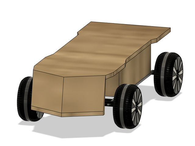
Figure 9.1 Com Bot 3D Model
As seen in Figure 9.1, the design of Com Bot implemented two gear motors found near the rear wheels, a compartment box to securely place electronics, and a wooden chassis with an aluminum frame that comes with a front “nose” like a train to allow for the Com Bot to easily travel through long grass and other obstacles. For the sake of visual purposes, we kept the wooden chassis in the 3D model as an oak color rather than the stained black chassis for visual clarity of the 3D model.
Figure 9.2 Com Bot Exploded 3D View
As seen in Figure 5.2 and the Exploded 3D Animation Video found in the link above, the design of Com Bot implements an aluminum square tubing for its rigidity as opposed to a flat bar to spam the distance needed. The aluminum chassis secures the front and rear axles to ensure that it is sturdy and rigid. Additionally, a compartment was created for the electronics to be safely placed into.
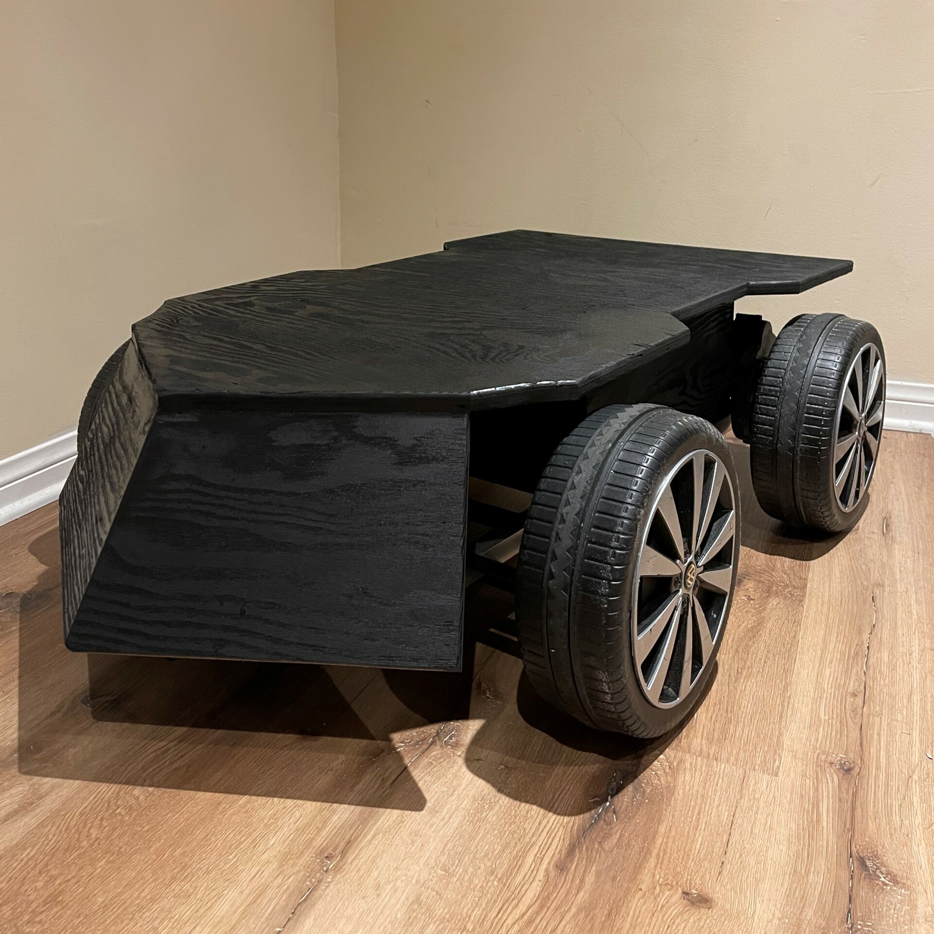
Figure 9.3 Physical Com Bot
After having created the physical Com Bot, one would take note of how the added curves and angles allow for a more aggressive look that is very much appealing to the eye while not losing very much of the top surface area for mounting projects.
Hardware Design
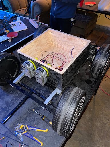
Figure 9.4 Com Bot Hardware Frontside
As seen in figure 9.4 the two 18V 4Ah batteries are attached to the chassis using battery holders seen in power tools. This was done with the idea that batteries can be easily removed and replaced when they run out of power. From the batteries, a switch is wired in to serve as an on/off switch but also a safety kill switch in case the connection was lost. From the switch, a terminal block distributes the power to the electronics inside which include the Arduino, motor drivers, and Bluetooth board. It can be noted that a buck converter steps down the voltage to 5V was added to decrease the voltage for the Arduino.
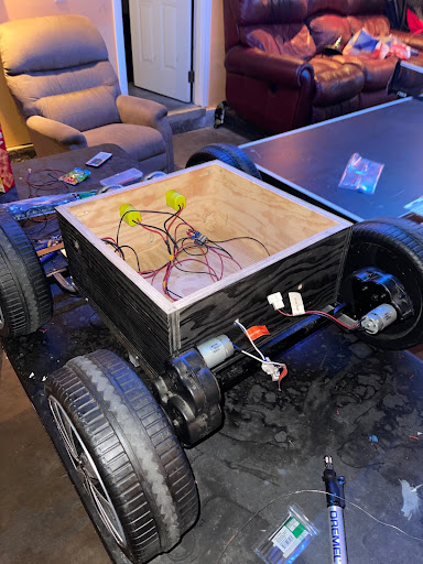
Figure 9.5 Com Bot Hardware Backside
As seen in figure 9.5, the motors are wired directly through the compartment box. It can be noted that an in-line connector was added to easily be able to disconnect the motors from the motor driver boards inside, without having to unscrew anything. All of the connections inside the box are done in a similar fashion. They use XT30U connectors that can be easily taken apart without any tools, to pull out and work on the electronics separate from the Com Bot.
Verification & Validation Test Plan
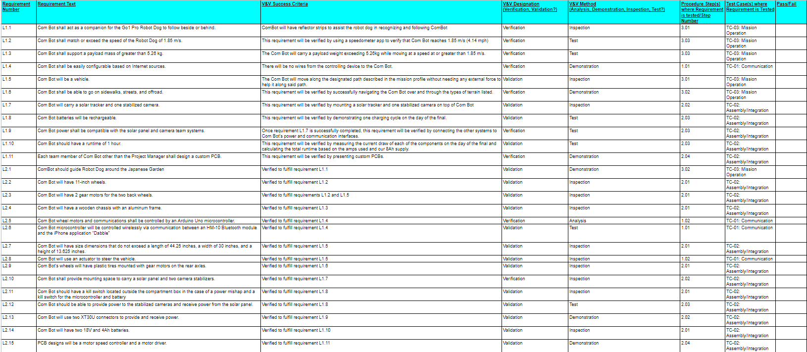
Figure 10.1 V&V Matrix
The V&V Test Plan and the V&V Matrix found above in Figure 10.1, allowed Com Bot to verify what requirements were being met as they go through a series of tests to pass or fail these requirements.
Concluding Thoughts and Future Work
The design of the Com Bot is what we had trouble with the most due to having a reasonable budget for our project. The number of designs we went through only pushed back our time on working on the actual project itself which caused us to be very limited on time. Another major issue that we encountered and wish we had discovered earlier was that the ArxRobot App functions with specific Arduinos such as an Arduino Leonardo which is based on the ATmega32u4 and at the time the Arxterra library has some issues working with Arduino which causes communication errors between the ArxRobot App and the Com Bot meaning we couldn’t confirm our results in telemetry as early as we would have liked to. Although our project was the first generation of Com Bot, the Com Bot team did very well in researching and analyzing resourceful ways to design the Com Bot. Future Com Bot projects should look to improve on the software as most of our time was lost due to waiting for the Arxterra libraries to be fixed but future Com Bot teams should also look into incorporating more motors and/or wheels for greater torque output.
References/Resources
References
R.1 How to Build a Robot – SDR Wiki
R.2 Preliminary Design Review Outline – Arxterra
R.3 How to Calculate Wheel Speed
R.4 Wheels vs Continuous Tracks: Advantages and Disadvantage
R.8 Battery Upgrade and Arduino Speed Control
Resources