Fall Biped 2016- Design Document

By: Hector Martinez
Approved By: Ijya Karki (Project Manager)

Table of Contents

Introduction

Requirement

The Biped design correlates to all level 1 and level 2 requirements because the body will house all components.

This design document reviews the design process for Biped starting at week 9 of the semester. Up until week 9, the manufacturing engineer for Biped was Ijya Karki and I was co-engineer for manufacturing of Prosthetic Arm. Having done my research on prosthetics and robotic arms, I had zero knowledge of biped robotics. With two weeks until CDR, I had a steep learning curve. In order to be an effective addition to Biped, I had to understand the current design, model it on SolidWorks, and build a prototype. There was no time for me to research biped technology or come up with a new design so we had to move forward with the group’s current design.

Version 1

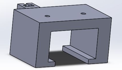
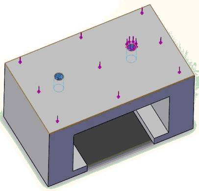
The Biped design at week 9 featured a weight shifting body, dual dc motor gearbox, shaft encoders, and servos. Weight shifting would be controlled by the servos, one servo would shift weight left and right to  aid in walking while the other servo would shift weight front and back to assist with incline walking. Shaft encoders would help track the position of each foot which would aid in coding. Everything would be housed in a multi layered body. This current design was under review by the current group and there were changes they wanted to make, I was asked to review the design and make changes necessary to ensure walking. I was also tasked with developing a turning mechanism because the current design did not have a way to turn.

13

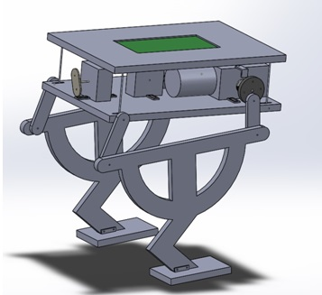
Fig. 1 – Design of the Biped at week 9 of the semester.

While simulating on SolidWorks, I discovered the walking mechanism was unstable and a more robust system was necessary. Based on the above design, the group wanted two motors that powered the legs connected at the front and the back of the legs, opposed to one at the front, we believed this would solve the stability issues while walking. I came up with the idea of adding servos at the bottom of the feet to assist with turning. Adding servos to the bottom of the feet would create ankles, we would then attach new feet to the servo to complete a turn.

Version 2

14

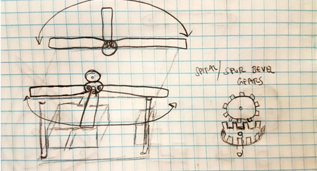
Fig. 2 – Preliminary drawing of how arms could be used to balance Biped.

Before I start modeling on SolidWorks I always put ideas on paper, by doing this, I can start to think about what aspects of my ideas are feasible. For example, figure 2 is a drawing of an initial idea I had for arms that could be rotated forward or backwards with servos to help when walking on inclines. Seeing it on paper, I realized that this design would not help with level waking because there wasn’t a way to extend the arms out to the side to shift center of mass left or right. By putting my ideas on paper first, I was able to quickly realize that this idea was not useful for Biped. Had I decided to simulate on SolidWorks only, I would have spent considerable time designing before coming to the same conclusion.

15

Fig. 3 – Ver. 2 of Biped design, featuring a servo at the ankle that will assist with turning.

The group believed that instead of having a body capable of shifting weight, a simpler approach was to have weighted arms capable of rotating 180 degrees on the horizontal plane. This would accomplish level walking as well as walking at an incline. Figure 3 features the servo housed in the leg with a foot attached with a servo gear. While the Biped is mid step, it has to balance on one foot, if the servo is turned in this position the whole Biped can turn and complete the step in a new direction.

16

Fig. 4 – Ver. 2 of Biped, featuring two motors to power the legs and the servos inside the body to power each of the arms.

By rotating the arms forward or back, the Biped would be able to shift its weight forward or back while walking on inclines. While taking a step on level ground, one of the arms would extend out while the other arm is rotated forward. This will shift the center of mass of the biped to one of the feet so the free leg can take a step. Figure 4 features the two servos inside the body which would control each arm. Below the body are the two motors that will be used to control the legs. One motor is connected at the front link of the leg while the other motor is connected to the rear link. The legs would have to be 180 degrees out of phase with each other to produce walking.

One week before CDR, the customer was asked to review the progress of the current design and to our surprise he was not pleased with any part of it. The customer had concerns that the feet were too far apart and weight shifting would not be accomplished. He liked the idea of having arms to shift weight, but did not like that the arms were extended out at all times. Apparently there was some miscommunication as to the number of motors the customer wanted to use for walking, he wanted the Biped to accomplish walking using only one motor. The only thing the customer liked about version 2 was the servos at the ankle to accomplish turning.

Version 3

With a clearer vision of what the customer wanted, I needed a crash course on robotic walking. I sought the help of Aaron Choi the manufacturing engineer for Velociraptor and he pointed me in the direction of the Theo Jansen Biped (TJB) toy. The TJB featured a single crank shaft to produce walking and ball bearings which acted as weights to shift weight while walking.

17

Fig. 5 – Theo Jansen Biped toy that would become the inspiration for the final Biped design.

By incorporating a single shaft to produce walking, we would be able to use a single motor. The customer insisted on using arms to control weight shifting, therefore, we did not look into incorporating ball bearings as a mechanism in version 3 of our design. At this point, I was extremely overwhelmed and I was seriously questioning my new found abilities on SolidWorks. Luckily, Aaron had 8 weeks of research on Theo Jansen walking technology and helped me, a lot. With his help, I was able to produce version 3 of Biped.

18a18b

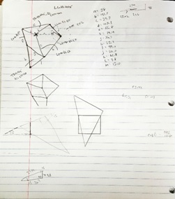
Fig. 6 – Preliminary sketch/design of Ver. 3 of Biped, featuring Theo Jansen linkages and a single motor.

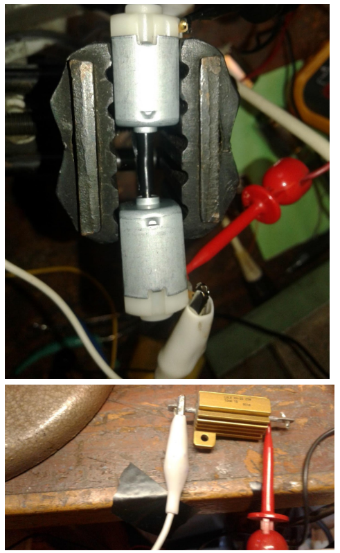
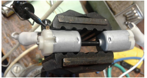
For version 3 of Biped I decided to get really creative in the way I would incorporate the servo into the Theo Jansen linkages. As can be seen above, I decided to house the servo in between the bottom triangle of the Theo Jansen mechanism. I believed that adding a servo to the bottom of the triangle would cause Biped to be too tall and possibly unstable. Brandon Perez, our mission systems and test (MST) engineer, provided me with a motor that featured a single shaft which extruded from both sides of the motor. I could use this motor to attach the legs to the shaft at 180 degrees out of phase to produce walking. Additionally, the width of the motor and single shaft gave the Biped a total width of 5cm, versus 9cm from previous versions.

yello

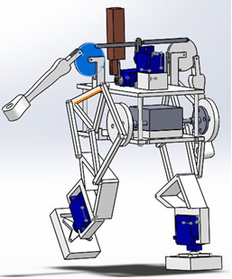
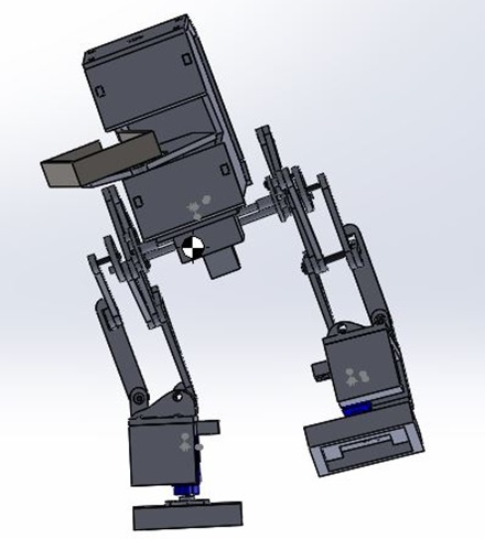
Fig. 7 – Ver. 3 of Biped. Additional features include servo controlled arms that hang to the side, TJB legs, servo controlled weight at the top to control incline walking.

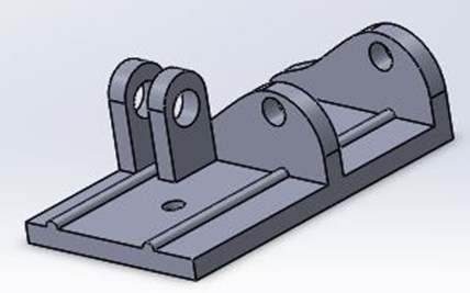
I continued designing taking into consideration our requirements. One requirement was to have color sensors that would be able to sense color pads on the floor. The figure above doesn’t show the sensor housing, but the reason for the boxy feet is because the sensors would be housed under the feet. We concluded that the best place for the color sensor would be as close to the floor since that’s where the color pads would be located. The figure below shows how these feet were designed as well as how the servos would attach to the feet.

19

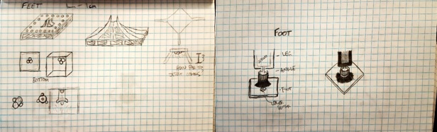
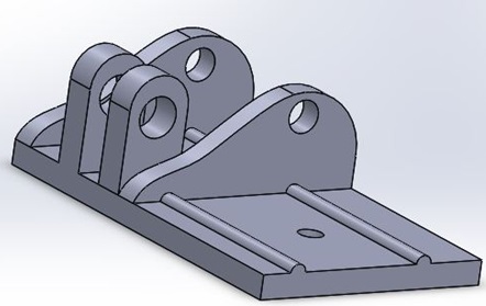
Fig. 8 – Design sketches of color sensor housing as well as servo/foot mate.

For CDR, we featured a Biped which we expected to look much like the final product. I added weights to the arms and top rear servo to simulate weight shifting for level walking and walking on inclines. The motor, servos, PCB, and 3Dot were all at their final locations. The faint outline of a body can be seen in the figure below. We were very pleased with this latest design and were confident the customer would be as well.

20

Fig. 9 – Design presented at CDR featuring attached weights, PCB, and simulated walking.

Unexpectedly, we were received a lot of criticism for our design. Once again, the customer complained about the width of the feet. The customer raised concerns that the Biped was too wide and would like the legs to be much closer together. The customer did like how the arms could move, but did not like how the design was implemented. The customer also liked the body design but did not like the body length, he thought the body was too long and would prefer something shorter. The criticism only grew when we presented our prototype because the prototype only validated the concerns of the customer.

21

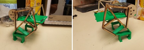
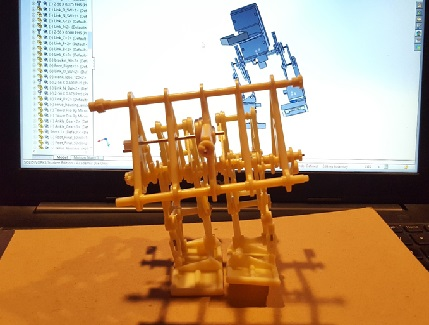
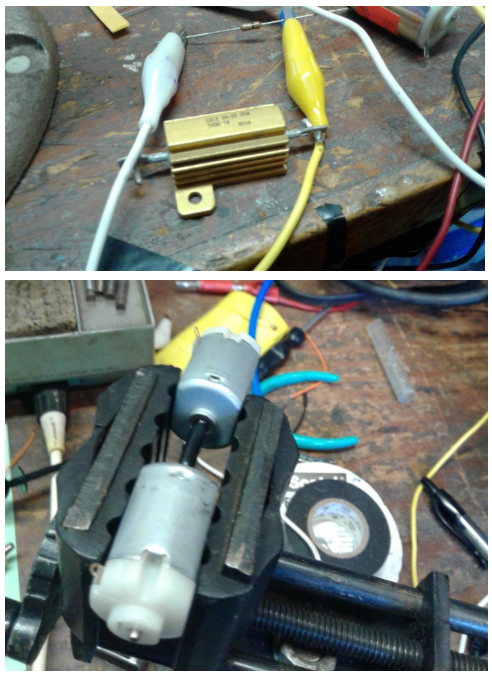
Fig. 10 – First prototype presented at CDR, the goal was to demonstrate static walking only.

The customer was not at all happy with our first prototype and gave us another week to present a second prototype. During the initial tests of this first prototype, we realized that the customer concerns were in fact right, the width of the Biped was too wide to be able to shift weight. We decided to scrap this design and work on something narrower. Figure 4 features the TJB toy with very narrow legs, the linkage design also incorporates weight shifting. Once again, I was under the gun to produce a new design in less than a week. Luckily we had in our possession, a TJB toy, and I was able to make all the measurements to create a design.

Version 4

22

Fig. 11 – Initial drawings of TJB crankshaft, lobe design, and spacing.

23

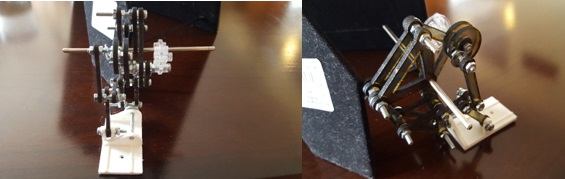
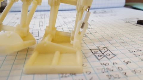
Fig. 12 – Leg design for Version 4/prototype 2 based on TJB toy.

24

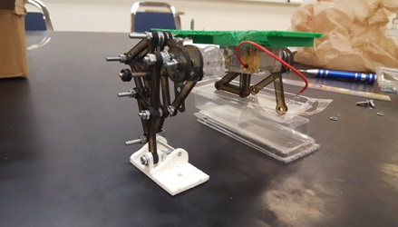
Fig. 13 – Incomplete prototype 2 with TJB toy inspired legs.

For version 4 I decided to copy the TJB toy, literally. I measured all the linkages, created them on SolidWorks, and laser cut them on acrylic. Laser cutting turned out to be considerably faster than 3D printing and was ideal for prototyping. Although prototype 2 was still somewhat wide it was a start in the right direction because the Biped actually demonstrated balancing and something that resembled walking. To fix the width issue, we needed to source a shorter motor shaft. The current shaft was 6cm and we were able to find one that was 3cm. This new shorter shaft would allow the Biped legs to be closer together. We also had issues with the gear that was provided with the motor, because Theo Jansen linkages are specific dimensions, we needed to scale our linkages to match the size of that motor gear. We realized after the prototype was built and during prototype 2 demonstration the motor would stall because the gear would hit the leg linkages. Additionally, the servo in the ankle had to be scraped because the TJB toy has a very specific foot linkages that help shift weight, the servo between these linkages obstructed the motion necessary to shift weight.

Version 5

With the issues of version 4 resolved, I was able to move onto the body design. After doing extensive work with laser cutting, I figured it would be much faster to laser cut a body rather than 3D print. By laser cutting joints into the body pieces, I would be able to fit these together with little effort.

25

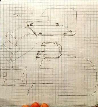
Fig. 14 – Sketches of what the body could look like. Featured are notches for easy assembly.

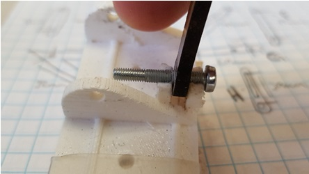
Based on CDR feedback, we knew the customer liked the body design which was inspired by the Star Wars ATST walker. We were not able to design arms that extended from the side of the Biped, the need for a narrow body restricted the amount of space available for additional servos. Instead I decided to house our external battery on a tray being held out by “arms”. These arms are laser cut on acrylic and the battery tray is screwed on to them.

26

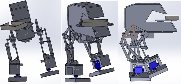
Fig. 15 – Final SolidWorks design of Biped featuring TJB legs, servo at the ankles, ATST body, and arms holding a battery tray.

Manufacturing went right up to the day of the final. Along with Alan Valles from E&C, we worked through the night to produce a walking Biped. While Alan uploaded and tested code, I routed, soldered, and managed wires. During the final presentation we played in Save the Human game in which Velociraptor Bipeds from other groups were to attack our human biped. Unfortunately, our Biped did not perform as expected. We did not have enough time to test the walking code with the balance code to produce stable walking.

27

Fig. 16 – Final Biped project as presented on the day of the final.

We were able to test the turning code which did produce turning. I believe if we had managed our time better we would have definitely produced a walking Biped.

28

Fig. 17 – Final design balancing on one foot to produce turning.

Conclusion

The design of this project was a long and grueling endeavor. Looking back, there are some things I would do differently. First, I would make sure to have clear expectations from the customer. When the customer is unsure of what he wants, the manufacturing engineer is expected to come up with a design that will wow the customer. This is a lose-lose situation because if such a design is reached then you are now on the hook for delivering every aspect of that design, and designs that wow are usually very intricate and complex. If such a design is not reached, then the customer is able to reject all designs, wasting value time in the process. This is even more important in a case like mine, where I had 8 weeks to do 16 weeks’ worth of work. Secondly, don’t allow others to influence your design unless you want them to. By allowing other people to influence your design you lose track of the wants of the customer. This doesn’t mean you shouldn’t seek for help, by getting someone else’s input you are able to attack a challenge in a different way. Although this was a tough project, it was very rewarding. Our leg design was by far the most complicated design out of all biped projects. The legs actually moved in a motion very similar to the TJB toy and when placed on a surface to walk, the Biped was able to walk with some human help for balance. If this group was together from the beginning of the semester, Biped would have walked and turned successfully on the day of the final.

Resources

[1] Solidworks 


Fall Biped 2016- Foot Design

By: Hector Martinez (Manufacturing Engineer)
Approved by: Ijya Karki (Project Manager)

Table of Contents

Introduction

Requirement

“Shall be able to walk a minimum speed of 0.32 mm/sec.”

After CDR, we discovered that our foot design was inhibiting the weight shifting that the Theo Jansen Biped (TJB) toy provides. After careful inspection, it was noted that a simple design oversight resulted in a failed CDR demonstration.

Foot Testing and Design Methods

8

Fig. 1 – TJB toy foot with weight shifted on left foot.

The image above shows the TJB toy with its weight shifted to the left foot. Notice the link on the right with the metal cylinder, this ankle link is what causes the TJB to lean to the left and shift its weight. In this position, the right foot is able to take a step. Also notice that the ankle link is not perpendicular to the foot, instead, the angle between the ankle link and foot is necessary to allow the biped to lean. Without this clearance the biped would not be able to shift its weight and take a step.

9

Fig. 2 – CDR foot with changed orientation of mounting bracket for ankle link.

While designing our biped, I ran into an issue which I believed to have a simple solution. The links for our TJB inspired legs are being laser cut, all the links are oriented the same direction except the ankle link. I decided to change the orientation of the ankle link to match the rest of the links because this would make laser cutting easier. I failed to realize that by changing the orientation of the ankle link I also changed the orientation of the pivot angle.

10

Fig. 3 – Close-up of 3D printed foot for CDR.

Notice in the picture above that the pivot angle of the ankle link is now parallel to the foot and not perpendicular as shown in figure 1. This change caused the mounting bracket to collide with the ankle link, restricting the angle necessary to make the biped lean. There was not enough time to 3D print a new foot with the proper mounting bracket orientation, thus, a quick solution was to break the top of the mounting brackets and super glue a machine screw to hold the ankle link in place. This was by no means an ideal solution and in order to make the foot work properly and redesign is necessary.

Conclusion

11

Fig. 4 – Redesigned foot which will be used on final product.

In order to make the foot work properly the orientation of the mounting bracket for the ankle link had to be changed to match that of the TJB toy. Additionally, the ankle link will have to be 3D printed to accommodate the orientation of the mounting bracket as well as the orientation of the rest of the leg links, which are offset by 90 degrees.

References

[1] http://www.rubberbug.com/walking.htm

Resources

[1] Solidworks 

Fall Biped 2016- Ankle Stress Test

By: Hector Martinez  (Manufacturing Engineer)
Approved by: Ijya Karki (Project Manager)

Table of Contents

Introduction

Requirement

“Shall be able to turn up to 180 degrees on each of its sides.”

In the COM Blog Post , I discussed the leg design inspired by the Theo Jansen Biped (TJB) which uses cleverly designed linkages and shafts to shift center of mass (COM) and facilitate walking. One of our requirements is that the biped is able to turn but the TJB does not allow for turning, to overcome this issue, we are adding servos to the bottom of the TJB foot which will allow our biped to turn. In order to attach a servo to the TJB foot, I designed a custom servo housing that will act as an ankle.

1

Fig. 1 – Custom servo housing that will screw directly to the TJB foot.

Once the servo is mounted, a new custom foot will be attached to the servo that will act as our new foot. This new foot will also serve as a housing for our color sensor which will go on the bottom of the foot. This color sensor is due to requirement that we must detect color pads that will be scattered on the playing field. In order to attach a new foot to the servo, a servo horn will be used that will be screwed to the foot.

Ankle Design

2

Fig. 2 – TJB foot with ankle (servo housing), servo, and new foot attached.

One concern for the ankle and the reason for this blog post is the structural integrity of the ankle while the weight of the biped rests on it. When the biped takes a step, all the weight of the biped will rest on the housing and we are worried that the ankle may fracture or break. One of our requirements is that the biped should weigh no more than 750 grams. An easy and efficient way to test the ankle at this weight is to use SolidWorks. By simulating on SolidWorks we can get a good idea of the type of stress the ankle will handle. In order to perform a proper stress test, a material, load, load direction and fixture must be set on the part.

3

Fig. 3 – Fixtures and load direction specified on the ankle.

The image above shows the direction of the load (purper arrows). Obvisously, the weight of the biped will only cause a vertical load on the ankle, which is set to our maximum possible weight of 750 grams. The material specified is ABS plastic. A fixture is specified at places that cannot or should not move, in the case of the ankle, fixtures are set at the mounting holes to the foot (blue arrows). When the simulation is run, these fixtures will act as rigid bodies which may be subject to break or fracture.

Conclusion

ok1ok2

Fig. 4 – Different angles of stress analysis of ankle.

The image above shows the results of the stress analysis. The results show where and how a part may fail. The blue color indicates the ankle undergoing limited stress while red indicates heavy stress and possible failure. In the case of the ankle, there is more stress at the fixture points, but based on the color scale, the ankle is able to support this load. The simulation also shows how the ankle may warp due to the load, but this does not mean this is how the ankle will warp. Additionally, the simulation assumes that the inside of the ankle is empty. Obviously with a servo sitting inside the ankle, this kind of warping will not be possible. Based on the results of the simulation we are confident that this ankle will be able to support the maximum allowed weight of 750 grams.

References

[1] https://www.arxterra.com/fall-biped-2016-shifting-center-of-mass-to-achieve-walking/

Fall Biped 2016- Shifting Center of Mass to Achieve Walking

By: Hector Martinez  (Manufacturing Engineer)
Approved by: Ijya Karki (Project Manager)

Introduction

Requirement

“Shall be able to walk a minimum speed of 0.32 mm/sec.”

A proper biped design must implement a weight shifting mechanism that allows for walking. This is because walking requires the weight of the object to be shifted to one foot so the free foot can be swung forward and repeat the process(1). The group responsible for the Velociraptor found a Theo Jansen inspired biped toy which implements a unique walking mechanism that integrates a swinging leg with a weight shifting ankle.

Process of Design

4

Fig. 1 – Packaging of Theo Jansen inspired biped, one propeller and ball bearings create walking.

The biped toy uses on motor, ball bearings, and a cleverly designed shaft to control both weight shifting and walking. We believe we can benefit from this design because one of our requirements states that our walking must be done with one motor. Other bipeds have implemented walking and weight shifting with two different mechanisms, some of the mechanisms to shift weight includes motorized hips, motorized knees, or weighted motorized arms, but these designs require multiple motors and servos. The simplicity of the Theo Jansen Biped (TJB) allows us to kill two birds with one stone.

5

Fig. 2 – Assembled biped toy with fan removed, shaft and links provide mechanism to walk/shift weight.

The design that we presented for CDR implemented Theo Jansen legs and used weighted motorized arms to shift weight. Through simulation on SolidWorks, we discovered that the width of our feet required an absurd amount of weight (1.5 kg) at the arms to shift the Center of Mass (COM) to allow for walking. It was after CDR that we realized that two things had to change with our design: 1) our legs needed to be much closer together, like the picture above, and 2) the biped needed something more than arms to assist with weight shifting.

6

Fig. 3 – CDR design. Checkered circle shows where COM is located when arm is extended.

After realizing that the TJB toy implements weight shifting and walking in one mechanism, we decided to implement it to our design. Our design features a scaled version of the TJB along with “arms” which hold a battery tray. This battery tray is attached to a servo which will turn left and right on the horizontal plane, this will help us mimic the ball bearings the TJB uses to assist with weight shifting.

Conclusion

7

Fig. 4 – Final design. Linkages and battery tray allow the COM to be centered over the foot.

Additionally, the smaller gearbox allowed us to shorten the width of our chassis from 60 mm to 40 mm which directly shortened the width of our feet. As the picture above shows, the linkages allow the biped to use its feet as anchors, with a proper motor shaft design, these allow the entire biped to lean. Thus, this allows its COM to shift over the foot and allows the other foot to take a step. By turning the arms and battery tray, we mimic the ball bearings the TJB uses to allow for extra stability while taking a step.

References

(1) http://www.rubberbug.com/walking.htm

Fall Biped 2016- Schedule and Burndown

By: Ijya Karki (Project Manager)

Table of Contents

Introduction

One of the most important documents that the Project manager produces is the schedule. The schedule will pace how your project will progress. The hardest part about preparing the schedule is to know which tasks to give each member and when to have these tasks completed.

Requirement

Creating the schedule correlates to Biped’s requirement: “Shall be ready to participate in the game ‘Save the Human’ on December 14th, 2016.”

Determining Tasks

Tasks should be determined based on the generic year schedule that Professor Hill provides and the work break down schedule that is presented at the beginning of the school year.

sch

Figure 1 Generic Schedule [1]

I determined the various tasks that should be completed by reading the job descriptions [2] and keeping track of the different expectations of each division. Then, I went through what I wrote down and highlighted the tasks that related to what Biped had to accomplish.

sch1

Figure 2 Work Break Down

Project Libre

Download project libre (http://www.projectlibre.com ) to create the schedule based on the work breakdown structure you come up with. Once project libre is opened up, create a name for your project and input the start date of your schedule (the beginning of the semester). Then proceed to fill out the tasks determined above and include due dates based on the generic class schedule.

sch2

Figure 3 Project Libre Open Screen

sch3

Figure 4 Project Libre Task Input

*Note:  various tasks can take longer than the ideal time. To compensate for this, make sure to add extra time to each task*

Once a task is completed click the column to the immediate right of the number column to mark the task as finished. This can be accomplished by marking a 100% for completion.

sch4

Figure 5 Completed Task on Project Libre

Biped’s Schedule

sch5

sch6

sch7

Figure 6-8 Biped’s Project Libre [3]

Burndown

            Once the schedule is complete, the next step is to create the burndown. The purpose of the burndown is to represent the progress of the group in a graphical form.

The burndown can be created on excel by listing a column of all the tasks mentioned in the schedule. Then make a row listing the number of the weeks in the semester. After that, fill out the boxes with the percent amount left to accomplish per task each week. This means that the left most column is 1 (representing 100% of the task left to fill in). As the project progresses each week, decrement 1 to represent the amount of work left to complete the task. The last two rows consist of the ideal row (total tasks spanned out with total weeks) and reality done (sum of task percent completed).

sch8

Figure 9 Burndown Excel Example

Biped’s Burndown

           schem6

Figure 10 Biped’s Burn Down

Conclusion

The burndown is based on the schedules, the schedule is created from the work break down structure, and the work break down structure stems from the job descriptions. The purpose of the burndown is to produce a visual representation of the project task completion. One can find the percentage of tasks completed by dividing the tasks completed by the total tasks.

Reference

[1]http://web.csulb.edu/~hill/ee400d/Lectures/Week%2005%20Project%20Plans%20and%20Reports/c_Generic%20Schedule.pdf
[2]http://web.csulb.edu/~hill/ee400d/Lectures/Week%2001%20Welcome/c_Job%20Descriptions.pdf
[3]http://www.projectlibre.com


Fall Biped 2016- Updated Stall Current Motor Experiment

By: Alan Valles (Electronics and Control)
Approved by: Ijya Karki (Project Manager)

Table of Contents

Introduction

The Purpose of this experiment is to measure the stall current of the Pololu 1117 motor. This will be done in order to compare it to its rated value of 800mA.

Introduction

A stall current experiment was performed in order to see the actual stall current produced by Pololu 1117, this was done at the recommendation of Project Manager and ENC Division manager. Stall Current was measured utilizing two Pololu 1117 130 motors. The motors were set up in a mini vise as shown. Two small electrical loads were applied, one 100Ohm and One 1Ohm. The currents into the driving motor and out of the receiving motor were measured. As discussed in ENC meeting this should give us our stall current. The stall Current for the Pololu 1117 is rated at 800mA on the Pololu website.

The first run of test result in really low output currents to the motor load. However, this was due to the shafts losing grip of each other because the electrical tape overheated and began to lose grip of the two shafts. Thus, the receiving motor did not spin at a strong frequency with the other motor. The tape was redone and the experiment current increased by about 60%. Thus, the measured stall current would be around 492 mA. However, the measured current from inside a Tamiya gearbox was about 500mA so this value does not make sense. However, if another device could be used to tightly grip both motor shafts in order to better sync their frequencies than the number may have been closer to the rated 800mA. However, the rated 800mA was for 6v DC but the motor will be operating at 5V DC. As shown in the experiment. Taking the maximum motor value of 335 and multiplying by two we get, 670mA. This value is less than the rated 800mA rated stall current. One can figure that the actual stall current will be under the rated 800mA

Electrical Load Driving Motor Current Load Motor Current
100Ohm 321 50
1Ohm 335 100
1Ohm Redo 328 164

 Conclusion


In conclusion an experiment was done to measure the stall current of the Pololu 1117. The results were not definitive. However, using worst case analysis, the stall current of the Pololu 1117 motor can be seen as less than the 6v rating of 800mA since we will be operating at 5v.

stall

stall1

stall2

Reference

[1] http://arxterra.com/pathfinder-motor-stall-current-test/


Fall Biped 2016- Project Manager- Managing

Table of Contents

By: Ijya Karki (Project Manager)

Introduction

Project Manager Roles include certain tasks that must be completed, example:

  • Defining WBS
  • Level 1 Requirements
  • Creating / Managing Schedule
  • Creating / Managing Budget
  • Final Project Video/ Documentation

There is a split of skills that a good project manager must possess, looking at the above list these skills can be differentiated with the words creating and managing. The easier of the two tasks include the creating. Documentation and guidance from the company CEO and President make creating a do-able process. The harder of the two skill sets is the managing portion.

Complications

What makes managing difficult? Managing can be difficult when one is working with their class mates and friends. There has to be a degree of authority established in the group so that there is an understanding that the Project Manager has the final says. This can become difficult when managing friends that one has spent years in class with.

Mistakes

From my communications class, I learned that these are typical issues that can arise when leading a group:

  • Not establishing authority at all
    • Failing to assign tasks
    • Failing to follow up on task progression
    • Failing to hold members accountable for failing to accomplish tasks
    • Being too lenient on pushing the deadlines back
  • Aggressively establishing authority
    • Expressing the “I know more than you” attitude
    • Assigning tasks with ridiculously unreasonable due dates
    • Talking over members during meetings
    • Passive Aggressively expressing feelings when members cannot accomplish tasks
      • Taking out anger on members grades
    • Being too friendly
      • Letting anything slide by
      • Neglecting due dates because they are trying too hard to make sure team likes them

Suggested approach

No one has perfecting good managing skills but these are suggestions and insights that can help one take a better approach than the mistakes listed above. Being PM doesn’t mean there is a choice that has to be made between friendship or PM roles. One can keep both tittles if they approach their responsibilities correctly.

  • Don’t be afraid to assign tasks to teammates- In fact, as PM, one has to assign tasks to members. Although your teammates are smart enough to know what steps must be completed to successfully build your robot, it is still helpful to assign tasks and deadlines.
  • During the old business portion of meeting minutes, ask for a progress about how far each member is coming with their tasks. They may need help and you can point them to the correct person that can help them. Or they might have forgotten about their tasks and the question will serve as a reminder.
  • Let your members know that you will hold them accountable if they miss the deadline. Staying honest from the start is a better approach than giving off the vibe that it’s okay for the teammates to turn in material late but then taking points off from their grade. Keeping an open communication is important to finding the balance of managing. If your members know from the start that failing to meet deadlines has consequences, then they will not have a valid reason to be upset at their grade if they fail to complete tasks on time.
    • Assign tasks with reasonable deadlines (depending on the task)
    • Some tasks are ongoing processes (like coding or updating requirements)
      • Set mini deadlines for various steps of the task
      • Example 1: ask ENC to produce code for parts of your robot for various demonstrations that occur throughout the semester ( PDR, CDR)
      • Example 2: If your systems engineer has to update the requirements, set mini deadlines for each draft (requirements continuously change throughout the year because they keep improving during each revision)
    • If a member cannot meet a deadline for valid reason (tests in other classes, presentation in 400D that is of more priority) then it is alright to push the deadline back
      • However, document in the meeting minutes the valid reason for changing the deadline
      • Avoid getting in the habit of continuously changing deadlines
        • One way to avoid this is by assigning tasks two weeks in advance so that you can check up on them and they have more than enough time to work on it
      • Never assign last minute tasks (unless it is an emergencies)
        • Your teammates have other classes they are also studying for and they will not appreciate last minute requests
      • Do not blame members for failures
        • A part of being PM means that you must keep the motivation and spirit of the group alive. If you have a negative attitude then that will affect the entire group.
        • Singling a member out and blaming them for problems will not solve the issue. Instead, you can talk to them to see why they lacked in their part and understand what needs to be changed so that they will not run into the same problem with the next task that is assigned to them.
        • Understand that you are a team. This means that no one can make a mistake alone. Although each member has individual tasks, the work you produce alone is collectively representative of the whole team. This means that one individual cannot be blamed for problems. Ultimately, the project manager is the most responsible individual for the group.
      • When grading member, make sure to split up grades for each assignment into parts so that they can get points for all aspects of their work. Do not just assign a pass or fail grading system. Let them know that long as they try their best then their grade will match that.
        • Example: Grading for meeting minutes can be broken down to different parts.
          • The grade can be out of 10 points total.
          • 5 points allocated to arrival time
            • 5 for arriving on time
            • 4 for arriving within 15 minutes past start time
            • 3 for arriving within 30 minutes and past 15 minutes of start time
            • 2 for arriving past 30 minutes of start time
            • 1 for arriving past 60 minutes of start time
          • 3 points allocated to participation
            • 3 points for actively participating during the meeting
            • 2 points for participating only during their part
            • 1 point for
          • 2 points allocated for completing the meeting minutes
        • This way, the members will not lose points heavily for not taking meeting minutes one week if they are active participants of each meetings.


Teammates that Lack Passion


In the event that a member in your group lacks passion, it is important to recognize these members from the start. The best solution can be to communicate with the member and figure out the reasoning behind why they are not committed and trying your best to motivate them. If that fails then you can converse with the Division manager to try and change or find a solution to the problem. Maybe your teammate wants to be in another group or there is a well skilled individual in another group that can help your teammate out. If all else fails, then communicate to the instructor the issue and the solutions you have already tried. Do not prolong this process, the further into the semester you go the more it will affect your grade if a teammate is unresponsive, uninterested, and idle. Be aware that if one of your teammates drop the course then you are responsible to complete both PM duties and the duties of the member that dropped.


Teammates that Lack Skill


In the event that a member in your group lacks skill, it is important to get them the help they need early on. Take initiative and talk to their division manager with a request that they spend more time on the material with your teammate or ask for a well skilled individual to be paired up to aid your teammate in their process. You want to avoid completing their tasks for them. If you get in the habit of finishing all of your teammate’s tasks, then you will have double the load and an idle member. The primary solution a skill lacking member should not be you taking over their job, but rather you directing them to their division manager for help.


Conclusion


THE DOS THE DONTS
Remain honest about grading Don’t take out anger with grades
Assign assignments at least a week in advance Don’t assign last minute assignments (unless an emergency occurs with the project)
Sit down with members and understand why they are struggling/figure out ways you can help them or direct them to the right person that can help Don’t single out members and blame them
Assign members tasks and follow up on them Don’t assume that members know what must be done and just wait for them to tell you what they completed
Keep grading scale fair by giving points to various parts of the project Don’t be lenient with deadlines


Fall 2016 Biped- Building the Game Arena

Table of Contents

Building the Game Arena

By: Ijya Karki (Project Manager)

Introduction

As the semester comes to an end, it gets closer to testing the actual product. This is where the profile objective and the mission profile from the CDR is brought to life. The game, Save the Human, is played by four teams (Wednesday Velociraptpr, Thursday Velociraptor, Biped, and Goliath). The Game committee met on December 3rd, 2016 to finalize the game rules. Then, Ijya Karki, Fabian Suske, and Kristen Oduca built the arena pieces.

Biped Project Objectives

The project objective is to design a 6th generation toy Biped robot that will statically walk using two feet with the goal of dynamic walking.

The Biped will utilize the 3Dot Board

The Biped will partake in an end of semester game: Save The Human

The project must be completed by December 14th, 2016

The budget must stay under $125.00

Biped Mission Profile

Biped shall compete, alongside other toys such as Goliath and Velociraptors, in an end of semester approximately hour long game: Save the Human. Biped should successfully walk, using Goliath’s live video feed as the field of view, from the opposite end of the room to the finish area without coming into contact with a Velociraptor. The Biped will maneuver through multiple obstacles by turning through walls, sensing color pads, balancing on six degrees inclines/declines, and stepping through uneven terrain placed on top of Linoleum floors.

Finalizing rules

The First Step to building the game arena was to modify and finalize the rules that were proposed at the beginning of the semester.  The original rules can be found under the Thursday Velociraptor blog posts: http://arxterra.com/fall-2016-game-save-the-human/

Suggested changes made:

  1. The incline angle should be 6.5 degrees allowing a ± 5 degree of handmade product production error.
  2. The Game arena should be at least 20% cardboard.
  3. The game arena (12 ft x 5 ft) shall be outlined with tape the day of the game.
  4. In the case that a robot steps out of the game arena, the robot will be disqualified from the game.
  5. Customer will have the power to place a few customizable pieces of the game including:
    • Four 1 ft x 1 ft uneven square cardboard pieces
    • Eight 6 in x 6 in uneven mini square cardboard pieces
    • Three 6 in x 6 in colored construction paper power ups

Building the Arena

Step 1

Determining the sizes of various cardboard pieces.

To fulfill that the game would consist of at least 20 percent cardboard, we had to create a total of eleven 1 ft by 1 ft cardboard uneven pieces and two 3ft x 1 ft hills.

               Arena size 12 ft x 5 ft –> 12 * 5 = 60 ft

               60*20%= 12 ft (thus the game must have 12 ft of cardboard to satisfy 20%)

Total cardboard pieces are:

  • Four 1 x 1 ft of uneven surfaces + eight 6 x 6 in of small uneven surfaces which results in=6 ft
  • One 5 x 1 ft of rectangle uneven surface = 5 ft
  • Two 3 x 1 ft hills = 6ft

Thus with 17 ft of cardboard used, the game committee successfully satisfied having building 20 % (12 ft) of the Arena with Cardboard.

build4

Step 2

Purchasing the necessary parts

              Cardboard, hot glue, and  glue gun was purchased at home depot.


Step 3

Using box cutters, scissors and parts purchased at home depot, Ijya Karki, Kristen Oduca, and Fabian Suske build the necessary pieces to fill the arena.

build

build1

build33

Fall 2016 Biped – PCB layout

Table of Contents

Designing the PCB

By: Hector Martinez (Manufacturing)
Approved by: Ijya Karki (Project Manager)

Introduction

Once the schematic design is complete by E&C engineer, Allen, it is time to design the PCB layout. The PCB layout needs to have a thought out design that will work logically and seamlessly with our project. Since our PCB will be a shield for the 3dot board, we also have to consider the dimensions of the 3dot board as well as space allocation.

Process

There are a lot of resources online that will explain how to layout a pcb, but one crucial bit of advice that I received came from our president Fabian, he suggested I start by grouping all the components that work together.

pcb1

Fig. 1 – New PCB project based on Schematic layout.

For example, our SX1509 GPIO expander contains a decoupling capacitor at the power input and 3 resistors that will work with our color sensor, by grouping those components together you begin to think about how and where these groups of components will be placed.

pcb2

Fig. 2 – Grouping of SX1509 and its attributed components.

As you continue to group all your components you begin to realize that some groups must be place at specific locations. The picture below shows the connectors for motor1 and motor2 are connected directly to the board at A and B. Additionally, since we will be using an external battery the LM1048IS that we will use to regulate that voltage must be close to the EXT battery connection towards the bottom of the board along with all its components.

pcb3

Fig. 3 – Continuing to group components you realize where some components must go.

Tracing

Once you are done grouping, the tedious job laying down traces to connect all your components. You may choose to place some of your smd components on the underside of the board or leave everything on one side. When you begin to trace, you want to try and route all your traces on one side, once you are unable to do this without traces overlapping, you can take advantage of Vias and placing traces on the other side of the board.

pcb4

Fig. 4 – Grouping complete, time to lay down traces. The blue component is the SX1509 on the underside of the board, this is done when space is limited.

Clearly, we have plenty of space to fit all of our components on one side of the board. Once the traces have been placed you may opt to go through and make all text on the silk screen the same dimensions. This makes your board visually appealing and will help when it is time to solder.

Conclusion

pcb5

Fig. 5 – You are done!

The image above shows red and blue traces that connect all components together, each is on opposite sides of the board. The planes is red or blue are grounds, these are meant to protect the board from noise, etc. Once you are done, you can admire your work.

Resources

[1] PCB layout

Fall 2016 Biped – Prototype Process

By: Hector Martinez (Manufacturing)
Approved by: Ijya Karki (Project Manager)

Table of Contents

Intorduction

The prototype process should be thought out and well planned. There needs to be a plan that includes a parts list, a schematic, tools list and clean workspace. I had none of these. Having been moved from Prosthetic Arm there was a steep learning curve on walking robotics as well as understanding the state and direction of the Biped project as it stood. It was an uphill battle which included two redesigns 2 weeks before CDR. Having done two prototypes there are some things that I realize I could have done differently had I not been under the gun.

Process

Prototyping starts with SolidWorks (or whatever program you’re using) taking into consideration how your project will come together. You have to think about the hardware you are using and think about clearance and tolerances, as well as your materials. For example, while laser cutting the leg linkages for our first prototype for CDR, I didn’t realize the mounting holes for all the linkages were too close to the edges which resulted in broken mounts because these were cut from wood.

prototype1

Fig. 1 – First prototype laser cuts, notice the mounting holes are really close to the edges

              prototype2

Fig. 2 – Broken linkages due to poor design

While putting together the second prototype for CDR, I decided to use acrylic and use M3 bolts to hold everything together. I didn’t consider the clearance of the bolt head and ended up having issues on several linkages hitting bolt heads due to insufficient clearance.

Another issue I ran into came from not researching the availability of part sizes, I assumed that I would be able to find M3 bolts up to 35mm. These were to be used on the feet to act as ankles and allow weight shifting. The feet were 3D printed and the mounting holes were set to 30mm, I decided to look for the hardware after printing and realized the longest M3 bolts I could get were 30mm.

prototype3

Fig. 3 – 30mm M3 screw used because 35mm screw was not available

Creativity

The thing about manufacturing is you have to learn to be creative. Some of the issues explained above had easy fixes, others didn’t, and for some the “fix” made things worse. For clearance issues I used spacers to create the clearance necessary. For the bolts that weren’t long enough I bolted them in such a way that they were still secured. Except for one of these bolts I decided to use superglue which fixed the bolt to the foot (Fig. 3), these were meant to fit loosely to allow for rotation. In this case you need to realize what you did wrong and fine the best solution. In my case the only option was to 3D print that foot again.

prototype3

Fig. 4 – Spacers and nuts used to lock linkages in place, locking nuts would have been a better alternative

Conclusion

The purpose of prototyping is to discover issues with your design as well as what is missing. For our prototype we wanted to know if our design would statically walk. While testing we discovered that our robot could not stand because the angle of the linkages would not allow it stand. Brandon, our E&C, suggested we make “shoes” to correct this issue. By making shoes we were able to move forward and continue testing our walking motion. While this was a quick fix for CDR, prototyping pointed to a major design flaw that needs to be addressed.

prototype5

Fig. 5 – Prototype with “shoes” to correct stance, and tape to hold the 3dot board

Resources

[1] Solidworks