Goliath Spring 2018 – Arxterra Custom Telemetry

By: Ryan Nguyen (MST Engineer)

Verified By: Ernie Trujillo (Project Manager)

Approved By: Miguel Garcia (Quality Assurance)

Introduction

Arxterra controls were set up based on mission objectives and requirements. Four modes of control during remote mode are predetermined route mode, recorded route mode, playback route mode, and route with avoidance. The predetermined route mode commands the Goliath to drive through a path that was determined by the E&C engineer, this path is most likely the shortest path through the maze. The recorded route mode records the path that the user inputs. The playback mode takes the recorded path from memory; Goliath then repeats the same path that was memorized. Lastly, the route with avoidance calls the avoidance subroutine and allows Goliath to navigate the maze while avoiding obstacles. The option allows movement, which gives the user the ability to override the modes and stop the motors.

Figure 1. Capture of the screen showing custom controls from Arxterra App

Testing

Figure 2. Control panel on Arxterra website, showing successful connection and video live feed

MST engineer tested community mode on the Arxterra app by linking the app with the Arxterra control panel on a computer. After mounting the robot, or the app, the control panels were able to receive a live transmission from the phone; furthermore, all controls and custom controls are showing up and ready to go. Battery and telemetry also present, indicating successful test.

Figure 3. Solid LED light indicates a successful connection between phone and Bluetooth module.

Since the 3dot board version 6 was not ready yet, the HM 11 Bluetooth module was tested separately on a breadboard with the Arduino standard board as the microprocessor. The code from the 3dot library was uploaded to the Arduino and several attempts to connect the module to MST engineer’s mobile phone was successful, indicating that the HM 11 Bluetooth module on the 3dot board version 6 should work.

References

  1. https://www.mouser.com/ProductDetail/Seeed-Studio/317030001?qs=SElPoaY2y5J3Mitl7sc2TA%3D%3D&gclid=CjwKCAjw_tTXBRBsEiwArqXyMlGpqg3f_3dhQyxT-aLVRoob5-ngyfoA-mhiYWZeuJaPzaxFBMzknhoC8UsQAvD_BwE
  2. www.arxterra.com/goliath-fall-2017-app-directed-rc-record-and-playback/#3Dot_Custom_Command_Setup


Goliath Spring 2018 – Detection Code and Demonstration

By: Tai Nguyen (E&C Engineer)

Verified By: Ernie Trujillo (Project Manager)

Approved By: Miguel Garcia (Quality Assurance)

Table of Contents

Introduction

The range finder, upon hearing reviews about it from previous semesters that it was a good choice above the ultrasonic sensor, has an ambient light sensor, range sensor, and IR emitter.  Depending on the ambient light in the room, the reflectance from the IR could vary.  The range finder has precise and accurate range detection up to 100mm. The SparkFun ToF Range Finder Sensor – VL6180 has an I2C address at 0x29.

How to use the Sensor

It was fairly simple to get a simple test running.

Step 1: Go onto the SparkFun website and locate the part.

Step 2: Under the documents tab, there is a link to the GitHub of the official example code and libraries.

Step 3: Download it all and inside the example code folder, copy over the SparkFun-VL6180 library and .cpp file.

Step 4: Go inside the code and make sure it is setup for I2C use. (ex: include <Wire.h>, Wire.Begin as well as the include for the library).

Step 5: Connect sensor to the I2C pins on the Arduino or ProMicro (pin 2 = SDA, Pin 3= SCL) as well as the VCC and GND pins to corresponding pins.

Step 6: Upload and open the Serial Monitor Ctrl + Shift + M and you’re done!

Test #1

I placed the sensor horizontal and parallel to the table and used a piece of paper and a ruler to test the accuracy of the range detection.  In a regular classroom light setting, the sensor was able to accurately detect the paper distance within 1-2mm and constantly displaying the same reading without a 20 point average.  Beyond the 120-144mm mark, the accuracy is about 2-3 mm off but still provided a precise reading.  If nothing is in the max range of the sensor, the sensor just repeats 255mm.  I did think that the 255 was only because the sensor variable was unsigned 8 bits long, but the max is just 255mm.

Figure 1: Ruler scanned for distance measuring

Strategy for the Range Finder

The choice to use the range finder over the ultrasonic was not only based on accuracy, but also on space and size of the sensor.  An ultrasonic sensor would prove too big for the Goliath and would not fit the L1 requirement of looking like a scale model of the Goliath 302 tank.

The first thing I wanted to do was reduce the false positives, since the sensor would always display the max range even when nothing was there.  The dimensions of the Spring 2018 400D maze room was announced and confirmed to be 4 x 4 inches.  4 inches translates to 101.6 mm.  To solve this issue, I decided to booleanize the readings of the sensor.  Anything above 101.6 mm is a 0 and anything below it will be a 1.  The booleanizing will help me detect and determine if there is an object in front of the goliath as well and allowing the Goliath 302 tank to navigate the far corners of the maze without detecting the wall of the classroom.  4 inches also fits within the high accuracy range of the sensor and will allow the robot enough room and time to take action by being able to sense an object from a room away.

Figure 2 – Red is Goliath 302 tank and Blue is an obstacle or another robot.

The next task was to also marking the position of the obstacle so that the Goliath would be able to learn that the path that it’s currently on is no longer usable and will need to either wait till the obstacle is gone or turn around and take a different path.  Obviously, we will be marking the obstacle virtually.  Things we already know: the obstacle is directly in front of the robot and is at least 1 room away.  Things we need to know to create the function: direction of the robot, which room number we are in (16 room numbers), as well as row and column.  The reason we need to know the room number is because the actual maze has no REAL walls and if we are in a room like Figure 3, it would be unnecessary to abandon the path we are currently taking.

Figure 3: Case 2

Essentially, the robot will detect an object, and then depending on the direction will take the row/col +1 and change the room that it’s facing to a room number 16 which is a room with 4 walls 0b1111 and also will add a wall to the room that the robot is CURRENTLY in, in the direction it is currently facing as well.  This way, the robot will see virtually that there is a wall in front of it and will be forced to make a different decision.  However, this case solution will only work for obstacles that are stationary and not moving, as once the obstacle disappears, the path is now available to the robot.  The reason why we care about the different cases is because there is also a case where the object is just another robot passing by in front of the Goliath through a T intersection.  Depending on the orientation of the passing robot, the path the Goliath is taking may still be available to take.

Figure 4: Range finder test code.

Conclusion

Overall, the range finder was amazingly accurate and simple to use.  A 0-255mm range is well within what we were looking for and suited for our purpose of only needing to detect 4 inches in front of the Goliath.  Booleanizing the readings helps to discern when an object enters the range of the sensor and resolved the error of false positives.


References

  1. https://www.sparkfun.com/products/12785


Spring 2018: Biped FOBO Existing obstacle avoidance software test

Written By: Jorge Hernandez (Electronics & Control)

Verified By: Miguel Gonzalez (Project Manager)

Approved By: Miguel Garcia (Quality Assurance)


In order to avoid obstacles, we implemented the SEN136B5B sensor ultrasonic code within the given navigation program from projectbiped.com. I also did my own code which turned on an LED to detect when the ultrasonic detected 8cm or less. This was made because Micro Fobo already had navigation code which used Ultrasonic to turn Right when it detected 5 cm and I did not want to take credit for code that was not mine. Within the provided code, the only changes we had to make is to have the function found Obstacle read the value of 8 cm. If Micro FOBO’s ultrasonic read anything above 8 cms, it would provide a zero, or a false to the function found Obstacle. Below is the given code with the minor changes in order for Robot avoidance.

Fig.1 Initial Code Test

Below is a video of the testing performed which would essentially have Micro FOBO walk and when detecting an obstacle at 8cm’s, instead of the LED going on, it would stop Micro FOBO completely.

https://drive.google.com/open?id=1ppkFJqBtTFxKPoDTRbCh50Uc4DUi5A1O

Initially, we wanted to have the LEDs that were on top of Micro FOBO’s head turn on when it detected 8cm but in our dem,o there was a loose wire which caused miscommunication and could not make FOBO move at all. Below is a video on how we would have used the idea of Robot avoidance with the Arduino code provided as well.

// Jorge Hernandez
//Ultrasonic Sensor HC-SR04 and Arduino Tutorial
//Dejan Nedelkovsk
// defines pins numbers
const int trigPin = 9;
const int echoPin = 10;
const int ledPin=13;
// defines variables
long duration;
int distance;
void setup() {
pinMode(trigPin, OUTPUT); // Sets the trigPin as an Output
pinMode(echoPin, INPUT); // Sets the echoPin as an Input
Serial.begin(9600); // Starts the serial communication
}
void loop() {
// Clears the trigPin
digitalWrite(trigPin, LOW);
delayMicroseconds(2);
// Sets the trigPin on HIGH state for 10 micro seconds
digitalWrite(trigPin, HIGH);
delayMicroseconds(10);
digitalWrite(trigPin, LOW);
// Reads the echoPin, returns the sound wave travel time in microseconds
duration = pulseIn(echoPin, HIGH);
// Calculating the distance
distance= duration*0.034/2;
if (distance <9){  // if less than 9 cm's then the LED will turn on
  digitalWrite(ledPin,HIGH);
}
else{
  digitalWrite(ledPin,LOW); // if not, LED will stay on
}
// Prints the distance on the Serial Monitor
Serial.print("Distance: ");
Serial.println(distance);
}

References

  1. https://drive.google.com/open?id=1ppkFJqBtTFxKPoDTRbCh50Uc4DUi5A1O

Spring 2018: Biped Breadboard Build and Test

Written By: Jorge Hernandez (Electronics & Control)

Verified By: Miguel Gonzalez (Project Manager)

Approved By: Miguel Garcia (Quality Assurance)


Our design ended up being breadboarded which fit inside of Micro FOBO’s head. The reason we had to resort to breadboarding is due to the fact of using a wrong chip. Originally Fobo operated on the CD-4017 decoder chip as we used the PCA9685 16-channel PWM driver on our PCB. Due to this error, in order to move Micro Fobo we need to use the 4017 decoder and with limited time, we breadboarded and tested.  In order to build and use the 4017 decoder to drive the 8 micro servos Micro Fobo uses, I drew up a schematic and pinouts to simplify which derive from projectbiped.com.

Fig1. Pin Out and connection of 4017 decoder

To clarify figure 1

  • RH= PWM connection to Right HIP
  • RLL= PWM connection to Right Lower Leg
  • RA= PWM connection to Right Ankle
  • RUL= PWM connection to Left Upper Leg
  • LH= PWM connection to Left HIP
  • LLL= PWM connection to Left Lower Leg
  • LA= PWM connection to Left Ankle
  • LUL= PWM connection to Left Upper Leg
  • NC= no connection
  • GND= ground connection
  • VCC= connection to 5 v

In figure 2 one can see the actual completed breadboard.

Fig.2 Completed 4017 breadboard connection

Fig.3 Testing each servo using FOBO Poser


Using this breadboard shield gave us full control of each individual servo when connecting a 4.7 V battery to it. The program used to calibrate was provided by Projectbiped.com which was called FOBO poser. The breadboard build and test were successful when testing individual micro servos. The walking test will be a more challenging task as it uses all 8 micro servos simultaneously.

Below is a video of the actual calibration.

Video

References

  1. https://drive.google.com/open?id=171cSjTzGN8j88Nwz8zHqaluC846qZIKd

Spring 2018 AT-ST Rapid Prototyping

By: Danny Pham (Manufacturing and Design Engineer)

Verified By: Intiser Kabir (Project Manager)

Approved By: Miguel Garcia (Quality Assurance)

Table of Contents

Introduction

3D printing using a plastic can cause inaccuracies in the dimensions and measurements of the piece that you are printing. Even if the pieces are designed to be simple shapes, dimensions can be skewed because plastic can become deformed while the 3D printer melts the plastic. To counter this, we printed many copies of different pieces. Despite our efforts, pieces continued to be skewed and we had to sand down the pieces in order for the pieces to fit in our prototype.

All of the components we printed are not simple shapes. The connectors have small edges and holes that 3D printing can not avoid making inaccuracies for. In order to remedy this, we printed many copies of a few complex pieces with different 3D printer settings to see if a change in accuracy, layers, and density would fix some of these errors. As you can see in the image above, many of the pieces came out very well. Some of the holes and edges in the pieces had to be sanded out in order to fit other pieces, but the main design and function of the pieces was printed correctly.

Printing components

Figure 1: These are the components we printed that will be put together to build the legs of the robot.

We printed the pieces with PLA so the printed components are brittle and easy to break. We had to replace these with new reprints and increased the number of layers and density so that the components weren’t as easy to break when putting the bot together.

Figure 2: One of the few pieces that broke when we were putting together the pieces.

The main piece that gave us the most trouble to print was the rotating shaft. Because it’s design is complex, the shapes are easy to deform. The component was also not flat, so we had to use a more supporting material as a platform for the material to sit on while it was 3D printing. When we printed the rotating shaft vertically, it was very easy to snap. After we changed the 3D printing setting to print it sideways instead of vertical, it was very sturdy yet it looked messy. Changing some accuracy settings allowed us to create a good rotating shaft that looked clean and was sturdy enough to rotate on the robot without breaking.

Figure 3: Rotating Shaft

The first print of the rotating shaft. It is a complex piece to print because of alternating circles and different sizes throughout the shaft. It was also very easy to snap because we printed it vertically.

Figure 4: Future print of the rotating shaft using higher precision settings and sideways printing instead of vertical.

The printed motor case fit the motor pretty well. The only thing I did not account for was having space for the wires to stick out without constraining the motor in the case. A simple solution to fix this was to cut out a bit of the edge on the side so that the wires can stick out while allowing the motor to fit in the case.

Figure 5: Printed case for the motor to sit in. It contains a hole on the side so the shaft can rotate freely without issue.

The pieces we printed required a lot of sanding just to fit each other. Almost all of the pieces had some inaccuracies in dimensions and shapes because of 3D printing. Some pieces were too big to fit in the holes for other components. We tried modifying the size of the holes and edges on Solidworks for reprinting, to account for 3D printing inaccuracies, and many other issues came up. These issues included having holes too big, dimensions still deformed, and more cost for paying for reprints. We decided that sanding down the components to fit each other would work best in saving money and also fixing the issue of deformities in the components.

Figure 6: 1 leg build

One leg put together after sanding down the pieces. Each component of the leg fit pretty well and the leg moved pretty well. The connections were not too tight or too loose.

Figure 7: Image of the printed components fitting together after a lot of sanding down.

Figure 8: Final prototype fully built

We will be designing a new box to fit the ultrasonic sensor, servo, and other electronics.

Conclusion

After putting the components together, the robot came out similar to the Solidworks model. There were some minor errors in the prototype. Some of the pieces were a loose fit instead of snug, but overall, the pieces connected to each other well and the motion of the leg was not disrupted. The shaft rotated cleanly and the leg moved in a Theo Jansen motion as intended.

References

  1. https://grabcad.com/library/theo-jansen-type-biped-walking-robot-strandbeest-1
  2. https://drive.google.com/open?id=10GJDTiolPUA9C2i3yNMLMN5Ndx_wRcU-
  3. Final 3D Model: Linked when blog is published

Spring 2018 AT-ST Final Model

By: Danny Pham (Manufacturing and Design Engineer)

Verified By: Intiser Kabir (Project Manager)

Approved By: Miguel Garcia (Quality Assurance)

Introduction

After the preliminary design review presentation, we decided to steer away from the split leg option that the previous semester used because it was difficult to balance. There were many complications with the previous design that caused the robot to fail, such as the unstable design of the legs and feet. To give us some ideas, Hill let us borrow a Theo Jansen Biped kit that moved with the Theo Jansen leg design using a fan. We decided that since the kit was well balanced, we could try to incorporate the use of motors instead of a fan into the leg design of this kit in order to make a walking robot that could walk and turn.

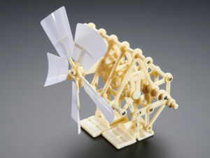
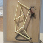
Figure 1: Theo Jansen BiPed Kit

This is the fully built Theo Jansen Biped Kit that moves by using the fan to rotate the shaft. It includes an automatic weight shifting mechanism and three gears that connect the fan and the shaft.

After building the kit, we saw that the main action that moved the kit was a fan that moved three gears in a gear system. A shaft that runs through the kit is rotated by a gear connected to the shaft. The rotating shaft moves the entire Theo Jansen kit. We modified the design of the kit so that instead of using a fan to move the kit, a motor on each leg would move each leg. First, we removed the fan and the gear attached to the fan.

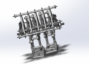
Figure 2: Theo Jansen Model on SolidWorks.

We found the entire kit on a Solidworks file on grabcad. The link is sourced below. This is an image of the kit on Solidworks after I removed the fan.

The kit above includes a rotating shaft that moves both legs simultaneously at different motions to create the walking motion. Since we are implementing a motor to do that for each leg, we split the shaft in half and implemented that on each side so that one shaft will move one leg, and the other shaft will rotate the other leg.

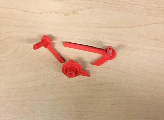
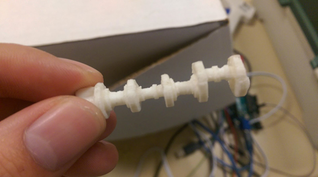
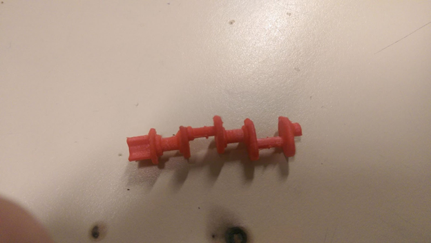
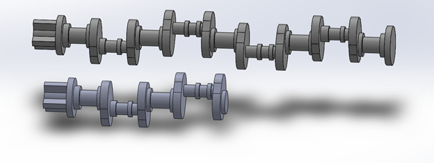
Figure 3: Original Rotating Shaft and the edited Shaft.

Image of the original rotating shaft and the edited shaft that is cut in half. We will be using the half shaft on each leg instead of just one shaft for both legs. Each shaft will be connected to their own motor through the gears.

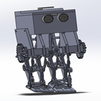
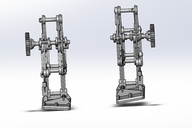
Figure 4: Leg Design on SolidWorks.

The edited rotating shafts and a gear are connected to each leg. The frame of the kit and the automatic weight shifting mechanism are removed from the model. This will be the framework of the legs.

After removing the chassis of the kit, we designed our own frame with the same concept as the kit model. The chassis will hold the rotating shaft in place while it rotates. It is also connected to the rest of the frame and will be the main anchor that holds the robot together. We added a general box on top of the frame to hold the electronics.

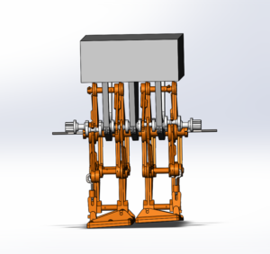
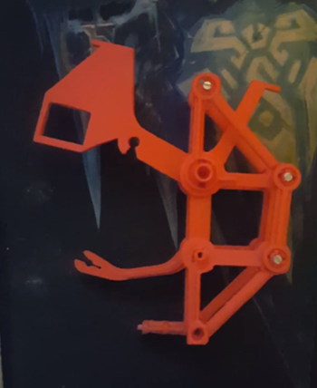
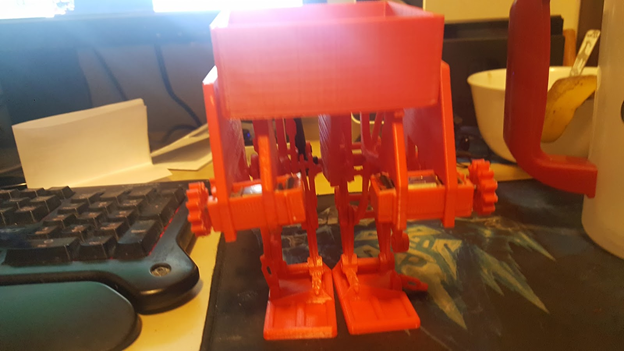
Figure 5: The legs are connected together with the shafts.

The legs are connected together with the shafts to three frame pieces that hold the legs and the body together. It also holds a box on top to fit electronics and other miscellaneous parts.

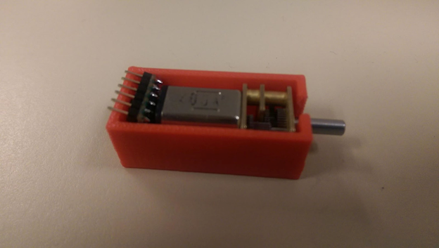
We initially planned to just stick the motor directly onto the rotating shaft on each end so that the motor rotated the shaft directly. However, Hill recommended that to balance the center of mass well, the weight of the legs should be closer together. If we went with having the motor on each side of the shafts, the weight would be shifted farther apart and make it more difficult to balance the robot. We decided to move the motor right in front of the legs so that the weight of the motor would be directly on the same plane as each leg. Since the weight would be closer to each other, the kit would have an easier time to walk while balancing itself. We created a case for our motors and modified our existing frame pieces to hold these motor cases. Since we are not putting the motors directly to the shaft, we created a two gear system.  The motor spins one gear and the one gear will spin the other gear that is directly attached to the shaft so that the motor will rotate the shaft. We went with a gear system that moved from small gear to big gear and that will create more torque for the robot to move.

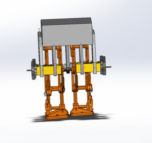
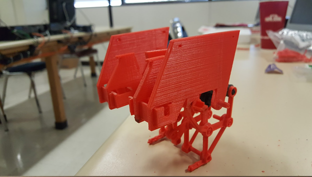
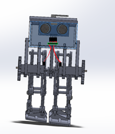
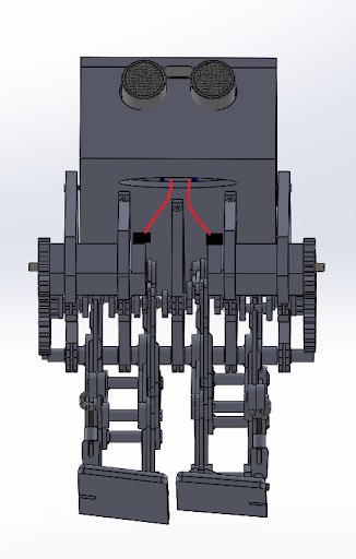
Figure 6: AT-ST with the motor case.

This is the robot after attaching gears and motor cases to the robot. We added two more frame pieces on the side to hold the motor cases and to hold the top box in place. This will add more stability to the robot and allow us to keep the motors closer to the center of the robot.

After finishing the leg and chassis design, we redesigned the box to hold the ultrasonic sensors, servo, and other electronic parts. First, we made the box longer to hold the 3DoT board and have space for the ultrasonic sensor and cables.

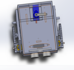
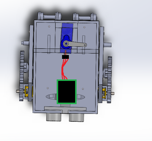
Figure 7: A transparent image of the redesigned box.

A transparent image of the redesigned box. I cut out holes in the front of the box to fit the ultrasonic sensor. A hole in the front bottom side of the box was also cut out for wires to come into the box from the two motors in front. I created small panels sticking out from the bottom side of the box so the 3DoT board will fit perfectly between the panels. Finally, I created a roof with a servo mounted to it so that the servo will act as the weight shifting mechanism.

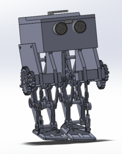
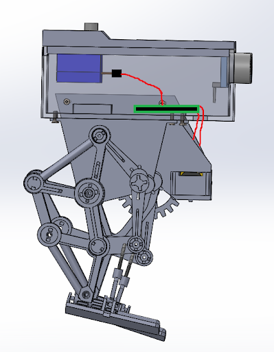
Figure 8, Final 3D Model.

Final 3D model of the robot. It contains the servo, ultrasonic sensor and the other electronic components in the box. There is a two gear system on each side of the robot.

Conclusion

There are a few things I would fix for this model. Because there are gaps between components in the model, it would be nice to hide some of the wires with panels that covered these gaps. I would also fix some of the screw holes for the model. In Solidworks, it is easy to reach these holes to put screws in, but for the actual model, it can be impossible to reach. Finally, I would adjust some holes in the box. When you 3D print the part, the 3D printing can deform the part so that your dimensions for size and holes are off. We had to sand down the parts to fix that. The issue for this type of design is that these components were not meant to be 3D printed. The design worked as intended but could be improved on. A solution to this is to redesign each component so that it is held together by screws instead of the connections and edges already on the kit components. Redesigning the components to basic connector shapes and using more screws to hold each part together will allow for easier 3D printing but maintaining the function of this design.

References

  1. https://www.adafruit.com/product/1841
  2. https://grabcad.com/library/theo-jansen-type-biped-walking-robot-strandbeest-1
  3. https://drive.google.com/drive/folders/10GJDTiolPUA9C2i3yNMLMN5Ndx_wRcU-?usp=sharing

Spring 2018 AT-ST Cable Tree

By: Samuel Yoo (Electronics and Controls Software Engineer)

Danny Pham (Manufacturing and Design Engineer)

Verified By: Intiser Kabir (Project Manager)

Approved By: Miguel Garcia (Quality Assurance)

Table of Contents

Introduction

This blog post shows the wiring design for the AT-ST robot. It will show how the wires connect from the board inside the box to the servo, ultrasonic sensor, and the motors outside of the box on the final model images.

The wiring for the AT-ST robot contains only ribbon wires. There were two different types of cables, one with the female-to-female connector and the female to male connectors. The female to male connectors were store bought and used for the ultrasonic sensor and the servo. The female-to-female connectors were made from components and used for the dc motor only.  There are two methods of making these type of wires; the first one is soldering a wire with a male connector and a female connector with male pins. After soldering the part together place, shrink wire on the connections and heat up the wire to get a good conductivity. The other method is getting a ribbon cable, housing, and female pins. With the listed components, first, remove some of the plastic off the wire to get the metal. Then taking the female pins, crimp them on the ribbon cable. After that step is done for each wire piece, insert them into the housing.

Wiring 

  • Wires – Red
  • Board – Black box Green outline
  • Connectors – Black box

Figure 1: Front Image of the wiring design.

Description: Front image of the wiring design. It shows wires connecting from the motors through the hole in the box to the board. The wires connect from the ultrasonic sensor inside the box directly to the board.

Figure 2: Top View of the wiring

Description: Top image of the wiring. The wires connect directly from the servo to the board.

Figure 3: Side view of the wiring design.

Description: Side view of the wiring design. It shows the wires connecting to the board from the servo and the motors.

Figure 4: Front angle view.

Description: Front angled image of the board. It shows a better view of the hole on the bottom side of the box and the wires connecting from the motors into the box.

Conclusion

The connectors for the wiring made it much easier to connect and disconnect the electronic parts. Some other issues with this design are that since the final model is not closed, there are a lot of gaps that wires come through that aren’t hidden. A simple solution to hide the wires is to design new panels that would go on the front that will hide the motor wires.

References

  1. Final 3D Model Blog post: Linked when Published
  2. Interface matrix: https://www.arxterra.com/at-st_interface_matrix/

Spring 2018 AT-ST Theo Jansen Leg

By: Danny Pham (Manufacturing and Design Engineer)

Verified By: Intiser Kabir (Project Manager)

Approved By: Miguel Garcia (Quality Assurance)

Introduction

The Theo Jansen Leg design is a design by Theo Jansen consisting of rods connecting to each other. One of the rods in the design is a static point that holds the whole leg in place and another rod which rotates in a circular motion. By rotating this specific connector in a circular motion, the whole leg moves in a circle and creates a walking motion.

Figure 1: screenshot of animation of Theo Jansen leg motion.

Description: The gif of the Theo Jansen leg shows the simulation of a walking motion by rotating a connector in a circular motion.

The reason the Theo Jansen Leg works well with motors is because the connector spins in a circle similar to a motor. One way to look at this is spinning a crank wheel.  If you attach a motor to the connector, the motor will spin that connector in a circular motion and create the walking motion for the leg. The motor is essentially turning a crank wheel that allows the rest of the leg to simulate the walking motion. A servo would not work with this design because servos only turn 180 degrees. A motor can spin this continuously and allow the leg design to walk forward without any interruptions.

Figure 2: Measurements regarding the Theo Jansen Leg Design.

Description: These measurements are used by Theo Jansen for his leg design. The green circle represents the connector spinning in the circular motion or the crank wheel. The red line represents the circular motion that the leg moves in to create the walking motion.

One main issue to look out for using this design is controlling how the foot pivots on the ground while walking. Keeping the foot parallel to the ground is essential in order to have stability in the leg while walking. If the foot is not parallel to the ground when it is in contact with the ground, the motion is disrupted by the angle of the connector next to the foot. This will disrupt the stability of the leg and cause the leg to fall over or not walk at all.

Conclusion

The Theo Jansen leg design works well with motors. This leg design will work with our requirement of moving the legs of our robot with motors. The main priority for this design to function with our robot is having stability while the motor is running the leg. The parallel foot to the ground is essential for keeping the leg motion smooth and stable.

References

  1. https://en.wikipedia.org/wiki/Jansen%27s_linkage
  2. http://scottburns.us/walking-mechanism/
  3. https://en.wikipedia.org/wiki/Jansen%27s_linkage#/media/File:Strandbeest-Walking-Animation.gif

Spring 2018 AT-ST Walk Code

By: Samuel K Yoo (Electronic & Control – Software)

Verified By: Intiser Kabir (Project Manager)

Approved By: Miguel Garcia (Quality Assurance)

Table of Contents

Introduction

During the creation of AT-ST, this is a program that allows AT-ST to walk. Note that this program is used for the current model and might need to be updated later on. The code is very straightforward as it only uses the motor and controls the speed. There are commented code for the servo to make it shift the weight of the bot.

Code

Figure 1: screenshot of code pt 1

Figure 2: Walk Code pt 2

Explanation

This code should not be used in the future irritations of the AT-ST. The major explanation of why it should not be used it because of the code being adjusted with some physical deformities with the leg. If the future irritations are going toused this AT-ST, then the code should be used to make the robot walk. However, a more appropriate approach to creating a walking motion code is setting the AIN pins and BIN pins to clockwise and counterclockwise. Keep in mind if the robot is facing you, the left motor must spin counterclockwise and the right motor must spin clockwise. The AIN pins should be programmed to the right motor and BIN pins should be the same with the left motor. To program the motor for a motor driver this table should be used

Figure 3: Table for motor control

The PWM should also be tested on each motor to determine what speed the motors are truely rotating at. This can be done with the shaft encoder, which I have not programmed with. There will be a link in the References for those who would want to learn how to program it.

References

  1. https://roboticbasicsblog.wordpress.com/tag/rotate/
  2. https://playground.arduino.cc/Main/RotaryEncoders

Spring 2018 AT-ST Which Way

By: Samuel K Yoo (Electronic & Control – Software)

Verified By: Intiser Kabir (Project Manager)

Approved By: Miguel Garcia (Quality Assurance)

Table of Contents

Introduction

In this code we are creating a which way sub routine. There are two methods of doing this, one being, code one which is the switch case decision. The other method is the index method which saves a huge amount of coding. The method used for the AT-ST is the index method.

Code

Figure 1: Whichway Code Screenshot

Figure 2: Code Screenshot Cont.

Figure 3: Code Continue

Explanation

The maze.h file contains the maze array which should be given in the EE444 lab training, but if not, there would be a link to it in the Reference. The code in the maze.h file also contains the two tables and the structure for the main programs. The enterRoom, turnInMaze, stepInMaze and roomInMaze all use the index. The index moves the values on the table to point at the appropriate row and column for each desired value. This method is really good and saves a lot space as mentioned above.   

References

  1. http://web.csulb.edu/~hill/ee444/Labs/Lab%204%20Arrays/Lab%204%20(C++).pdf
  2. http://web.csulb.edu/~hill/ee444/maze.h