Spring 2018 AT-ST Custom PCB Layout/Design

By: Shweta Hebbalkar (Electronics and Controls – Hardware)

Verified By: Intiser Kabir (Project Manager)

Approved By: Miguel Garcia (Quality Assurance)

Table of Contents

Introduction

For the AT-ST project, one of our goals is to create custom PCB using Eagle software. This software allows the user to generate PCB layouts, in order to use the Eagle software I need to learn how to use the software. With lack of experience using the Eagle software previously, it took me a week to two weeks to learn the general concept. So overview of the concepts is learning a PCB, also it is most common named “printed wiring board” or “printed wiring cards”. So it is a board that has lined and pads that connect various points together.

Transformation #1

The first thing I ever built in the Eagle CAD is the flowing figure, a schematic and PCB layout. In the figure one the schematic is for the op-amp amplifier I followed this schematic from the workshop that was directed by Chris and others.  Creating the PCB layout was easy to follow basically I moved all the components into the black box and then AutoRoute the trace.

Figure 1: Schematic

Figure 2: PCB #1

Figure 3: Frontside of PCB #2

In the picture above, there are traces that electrically connect the various connectors and component to each other. A PCB allows signals and power to be routed between physical devices.

Transformation #2

After two weeks of refining my skill in Eagle CAD with help of the Chris and others at the workshop. I was finally started designing my very first custom PCB layout schematic. When I was designing the circuit, it took me four days to find the library that I need it to create the custom PCB layout. Eventually, I was successful to get all the all the library that I need it, for example, the ultrasonic sensor the gyroscope and i2c expander as shown below in schematic and the board.

Figure 4: Iteration #2 schematic

In fig 4 the schematic was just placed on the template thinking that they will be all connecting in the board.

Figure 5: PCB layout

In Fig 5 the board layout, I placed all the components in the black box and then arranged in preferred to make it in compact space due to requirement. Afterward, I try to route the i2c expander with an ultrasonic sensor. In conclusion, from these we all understand that I need more practice then I thought and also need more clear instruction as well.

Transformation #3

In order to send in the custom PCB layout to print, I have to illustrate my board to get approval from our Customer. Which is very useful because professor Hill helped me the lot to make my board even more efficient. For example, the routing line has to be the 45-degree angle and it should be the clean line. If I am using polygon plane the top one supposed to be ground and the bottom one should the source. Always make sure to have the right parts if not then I redo the board design. According to the team consensus, we decide that we are going to make our PCB as the front shield.

Though this images below is my final version before getting approval. I had to go through many iterations. I had to connect all the lines in the schematic and I have to make it look easier to read for others.

Figure 6: New updated Schematic

Figure 7: Updated PCB

Unfortunately, we did not inform our professor that we are changing our custom PCB from top shield to the front shield. Still, the images above and I went with and I design our PCB.  Then After emailing professor this board to get approval from our professor however he emailed me back saying that why am I using the front shield. Then I respond to him saying that we need to use the analog pin, therefore, we are using the front shield. However, the professor said we don’t need to use analog pin we need digital pins and that pin is given in the top shield so I have to redo the custom PCB again.

In conclusion, we did not inform the customer beforehand with my design. Which means that I need I made myself double the work. The more time I spent with design PCB, I became more cautious because we would have to save time and print the board right away because printing board takes a lot of time.

Transformation #4

After getting some feedback from Customer, I already lost a big amount of time, which means that I get to have less time printing board, however, I started designing the top shield. With many changes like the routing and the get the right parts package size for schematic chaining any specifications according to professor liking I get approval the image below.

This is schematic is final schematic after many variations.

Figure 8: Finalized Schematic

The final PCB board that we send it to OSHPARK to print.

Figure 9: Finalized Custom PCB

Maintaining low expectation with my first board design because they had lots of problems and the final was my 25th board design that had the fewer error. The schematics are important and trying to design a board with a good schematic in place first is an exercise in futility.

In conclusion, I have learned lot more from Hill then division manager although they were helpful, mostly it is our job own responsibility to learn the eagle software.

Goliath Spring 2018 – Mock Up Motor Under Load

By: Ryan Nguyen (MST Engineer)

Verified By: Ernie Trujillo (Project Manager)

Approved By: Miguel Garcia (Quality Assurance)

Test Description

A mock-up motor under load test was performed to determine how much current the Goliath’s motors would draw while being put on mock loads, which were weights. Since the amp-meter has a large resistance, direct current measurement was not possible, as only a very small amount could flow through and the motors didn’t even turn. In place, a voltage measurement was taken over a 100-ohm resistor to determine the current of the motors. The motors would lift the weight, hung on a gear, and the highest voltage is recorded. Testing stopped when the weight reached 80 grams, any more than that the motors would not move. 80 grams per motor is quite good as the Goliath robot would probably weigh between 150 – 200 grams. The test also suggested that the maximum current pull from motors are about 35 mA each, which is useful for the power budget.

Figure 1 – Table displaying voltage and current values of both motors at varying loads.

Resources


Goliath Spring 2018 – Custom Shield Layout

By: Milton Ramirez (E&C Engineer)

Verified By: Ernie Trujillo (Project Manager)

Approved By: Miguel Garcia (Quality Assurance)

Table of Contents

Introduction

This blog post will go over all the different iterations for the PCB layout for Goliath.

Eagle Layouts

Figure 1. Layout for the Gyro PCB

This design was just a rework of the ITG-2200 breakout, to fit on top of the 3DoT board. All the capacitors and resistors are connected to ground and are paired together so that it could look nice. Same goes for all of the capacitors and resistors connected to voltage source 3.3V. This layout is also using an old set of pins that have SCL on the right side of the connectors and SDA on the left side. The top layer is connected to ground while the bottom layer is connected to 3.3V

Figure 2. UV Sensor board.

This board connects two UV sensors to a multiplexer, which connects to the SDA and SCL of the 3Dot board. The multiplexer is on the bottom layer of the board. This was done to make space on the top layer. All the resistors that were connected to their respective part were placed together. For example, resistors R1, R4, and capacitor C1 are placed next to U4. The six pins were placed on top so they can connect to the six pins on the bottom of the 3dot. This was an earlier design of the 3dot since the new 3dot has 8 pins now. Same as the gyro, which the top layer is connected to ground and bottom is connected to 3.3V.

Figure 3. The final board design for the Goliath PCB.

The final layout combines the previous two layouts. In this layout, the connectors on top are for the path-finder breakout board. The connectors on the side are the so that our PCB can be mounted on top of the 3dot board. The UV sensors are spaced at 1.7cm. The LEDs are both placed under the UV sensors so that the best possible readings from the UV sensors can be obtained. The capacitors C1, C2, and C5 are all coupling capacitors and are placed as close as possible to the voltage pins of the two UVs and Gyro. The I2C expander from the previous design was replaced with the 2 address I2C multiplexer PCA9540BDP. The pull-up resistors, the range-finder connectors, Gyro and I2C share were replaced with a resistor array to make more space on the top left side. This helped because the SDA and SCL pins are on the top left side and needed as much space as possible since the I2C, Gyro, and range-finder are all connected to those same pins. The top layer of the PCB is grounded while the bottom layer is connected to the voltage source 3.3V.


These next two figures are earlier designs of the final design since this is the version that went through many iterations.

Figure 4. The first iteration of the final PCB.

This circuit used an 8 address multiplexer and had a set of pull-up resistors for both the multiplexer and gyro. The coupling capacitors are also not where they’re supposed to be. Also, this design was still using the 8 address I2C. Since this chip was big, it was placed in the bottom layer to make space for the rest of the parts. The LED’s are also missing in this iteration.

Figure 5. Another iteration that was closer to the final design. One notable difference from this design is that I tried to use connectors for the LEDs. This iteration has the 2 address I2C and the resistor array added.

Parts Required

Figure 4. Final Parts list for the PCB

Conclusion

The PCB was approved April 21, 2018. Was ordered on April 26, 2018, and will arrive May 5, 2018.

References

  1. https://www.sparkfun.com/products/11977
  2. https://www.digikey.com/product-detail/en/nxp-usa-inc/PCA9540BD118/568-1844-1-ND/789976
  3. https://www.adafruit.com/product/1981
  4. https://www.adafruit.com/product/2717?gclid=CjwKCAjwlcXXBRBhEiwApfHGTd0vBvwKsP8KS7RMRyuV4j720AR6SxzWgmhaRgt9JazlS-hEpLF4HhoCSbQQAvD_BwE

Goliath Spring 2018 – System Schematics

Written by Milton Ramirez (E&C PCB Engineer)

Verified by Ernie Trujillo (Project Manager)

Approved by Miguel Garcia (Quality Assurance)

Table of Contents

Introduction

These are the schematics from the multiple PCB boards that were designed for the Goliath. The PCB schematics consisted of a gyro shield, a UV shield, and the final design which combined the previous two designs.

Schematics

Figure 1. Gyro Shield Schematic

This schematic is an exact copy of the ITG-2200 breakout board schematic. The only difference is the two 8 pin connectors. This was done so that it can go mounted on top of the 3dot board. The gyro connects to the SDA and SCL pins in the connectors.

Figure 2. UV Sensor Shield Schematic

This schematic has a 6 pin connector that the I2C expander connects through the SDA And SCL pins. The first UV sensor is connected to the SCA0 and SCL0 pins in the I2C expander, and for the other UV sensor, the SDA, SCL, SDA1, SCL1, SDA0, and SCL0 pins have pull-up resistors. Finally, there is one LED to find the UV sensors to read the lines in the maze.

Figure 3. Final PCB Schematic

Figure 4. Close-up of the left side of the schematic for the final PCB.

Figure 5. Close-up of the right side of the schematic for the final PCB.

Conclusion

In the end, we scrapped the last two designs and combined them into one PCB. This PCB connects SDA and SCL to the I2C expander and the gyro sensor.  This time we added connectors on the board for range-finder which also connects to SDA and SCL pins. Since all three of these are connected to the same SDA and SCL, there is only one pair of pull up resistor for all three parts. This pull-up resistor was also replaced with a resistor array. The I2C expander was changed from 8 addresses to 2 addresses since we only need two for the UV sensors. The gyro lost the jumper, which was designed just in case we needed to connect an external clock. Two LEDs were added since it makes it easier for the UV sensors to read the line if each sensor has its own LED.

References

  1. https://www.sparkfun.com/products/11977
  2. https://www.digikey.com/product-detail/en/nxp-usa-inc/PCA9540BD118/568-1844-1-ND/789976
  3. https://www.adafruit.com/product/1981
  4. https://www.adafruit.com/product/2717?gclid=CjwKCAjwlcXXBRBhEiwApfHGTd0vBvwKsP8KS7RMRyuV4j720AR6SxzWgmhaRgt9JazlS-hEpLF4HhoCSbQQAvD_BwE

Spring 2018 AT-ST Work Breakdown Structure (WBS)

By: Intiser Kabir (Project Manager)

Approved By: Miguel Garcia (Quality Assurance)

Table of Contents

Introduction

The idea of the WBS is to breakdown who does what for the project. The Project Manager assigns all tasks to the group and divides the work into who is the best fit for the job as well list out the tasks from the task matrix. WBS looks like a flowchart that shows where each specific task goes to per division.

WBS

Figure 1 Workbreak down structure

Description

The idea of the WBS is the breakdown who does what for the project based on the task matrix and job description. It is broken down to each division the task belongs to. Some people within groups also volunteer to task outside of their specialty or working with others. So the breakdown is structured around this. This WBS will be used to help create PBS.

References

  1. https://docs.google.com/spreadsheets/d/1hYPJQWkk-FtJcmEzwJh0wv_LhTuU2_OUg5NqZrFQ7T0/edit#gid=1180904142
  2. http://web.csulb.edu/~hill/ee400d/Lectures/Week%2001%20Company%20and%20Mission/d_Job%20Application.pdf
  3. http://web.csulb.edu/~hill/ee400d/Lectures/Week%2001%20Company%20and%20Mission/c_Job%20Descriptions.pdf

Spring 2018 AT-ST Project Specific Requirements and Objective (L1&L2)

By: Intiser Kabir (Project Manager)

Approved By: Miguel Garcia (Quality Assurance)

Table of Contents

Introduction

The Level 1 and Level 2 requirements follow both the S’18 Project and Mission Objectives and EE400D S’18 Project and Mission Objectives documents. Also what our team is hoping to accomplish by the deadline May 15. Level 1 is for general requirements that the AT-ST is hoping to achieve. Level 2 requirements go down to specific requirements for each member hoping to accomplish.

Level 1 Requirements: assigned to all Members

  1. AT-ST shall walk on a level surface
  2. AT-ST shall use Theo Jansen leg design
  3. AT-ST shall look like an AT-ST Walker from Star Wars
  4. AT-ST shall turn left, right or turn around
  5. AT-ST shall support its own weight
  6. AT-ST shall not exceed pass the size of 6’’x 6’’
  7. AT-ST shall not walk through walls
  8. AT-ST should walk backward
  9. AT-ST should have a dynamic walk
  10. AT-ST should jump.

Level 2

Level 2 – MST System/Subsystem Requirements: Assigned to Joseph Cho (MST)

  1. AT-ST shall use Gyro to obtain information for calculating the center of gravity.
  2. The 3DoT Board shall receive commands from the Arxterra app via Bluetooth Transceiver. It will decode and transmit data to servos, PCB and other components of the robot.
  3. The power source shall be able to fit inside our robot and must be integrated into the AT-ST such that it doesn’t conflict with the functionality of the robot.

Level 2 – Electronics & Control Requirements: Assigned to Shweta Hebbalkar (Hardware) and Samuel Yoo (Software)

  1. AT-ST shall use 2 DC Motor to move the legs (1 per leg).
  2. AT-ST shall use a Servo Motor to adjust the center of gravity of the robot so it can turn
  3. The Battery’s duration shall last up to an hour.
  4. AT-ST shall use 2 shaft encoder to keep track of the leg motion
  5. AT-ST shall utilize 2 Lithium Ion Battery – 2Ah for its power supply.
  6. AT-ST shall use an ultrasonic sensor to sense other robots within 0.5-meter radius
  7. AT-ST shall use UV sensor to navigate through the maze.

Level 2 – Manufacturing Requirements: Assigned to Danny Pham (Manufacturing)

  1. AT-ST shall have a total weight of 600 g and weight will be properly distributed to the body and legs to support its own weight while walking.
  2. AT-ST shall not exceed dimensions of 6” x 6” in order to fit in the maze and walk and properly turn without hitting the walls in the maze.
  3. AT-ST shall have its body 3D printed (ABS)
  4. AT-ST shall have legs 3D printed (ABS)

Conclusion

The Specific Requirements and Objectives help incorporate design ideas and ways we can make our robot function. It will also help us understand our restrictions regarding features and objectives the robot can successfully do. We incorporate ideas used in the previous Velociraptor for our AT-ST Walker because they have similar ideas that we want to use. We also try to understand why they didn’t work in the past and want to fix issues regarding the Velociraptors for our design. We are basically like the Velociraptor without the head and tail, and the BiPed without servos to control the leg movements.


References

  1. https://docs.google.com/document/d/1cyjXSxK7dr–Xwo8d_XS3zJ5vIeamPyu2YjNbjs5Hzw/edit#heading=h.ieqe41766sxa
  2. https://docs.google.com/document/d/1kwObe9HkGBeCjMYAETA5GiChyxhY1o6bpcmhWKbNFv8/edit
  3. https://www.arxterra.com/spring-2017-velociraptor-preliminary-design-documentation/
  4. https://docs.google.com/spreadsheets/d/1HHaQliwvLYbqErqJi2AVOlqGEzNX7grKOYJ2CBUFQ7M/edit#gid=0

Spring 2018 AT-ST Command and Telemetry (Mobile App.)

By: Joseph Cho (Mission, Systems, and Testing)

Verified By: Intiser Kabir (Project Manager)

Approved By: Miguel Garcia (Quality Assurance)


Table of Contents

Introduction

The AT-ST will be remotely controlled using an Android or Apple mobile device with Bluetooth connection. Once requested to the Arxterra, there will be a mobile app available to download. Using the mobile app, ArxRobot, you will be able to create custom command and telemetry for the connected robot. The mobile device will be connecting with the 3DoT board via Bluetooth. “User” or the person controlling the mobile app will be able to control the prototype robots with their commands.

Main screen of ArxRobot app

Figure 1: Screenshot of the Arxterra App

Description:
On the main screen, you will only see the up-down controls when you first launch the app. The app is currently modified to fit the AT-ST remote controlling. There is a D-pad (directional pad) to control the movements, four selected for the different phases, and one boolean for the run.

Definition

Movement is referring to the AT-ST moving forward, turning left, and turning right. Each command is activated by pressing up, left, and right respectively on the D-pad.

Phases are referring to different stages that AT-ST will go through. “Select” is a command type that returns which phase the user selected back to the 3DoT board to be processed. “Sleep” is a phase that the AT-ST will be resting and wait for further commands. “Learning” is a phase that the AT-ST should navigate through the maze following the user’s command and recording those commands. “Shortest path” is a phase that the AT-ST should navigate the predefined shortest path through the maze. “User define path” is a phase that the AT-ST should navigate the learned user-defined path.

“Boolean” is a command type that returns OFF or ON (false or true) based on the user’s input. The “run” boolean will only affect the “shortest path” and “user-defined path” phases. AT-ST will start moving on its own if “run” is ON and in phases “shortest path” or “user-defined path”.

Flowchart of Arxterra app

Figure 2: Flowchart explaining the how the App works

Description:

The “select” will determine the four phases: Rest, Learning, Shortest Path, or User Defined Path. Based on the phase, AT-ST will act out the following. At “Rest”, AT-ST will do nothing. Durning “Learning” phase, AT-ST will move according to the User’s command and record the movements to learned user-defined path. In “shortest path” phase, AT-ST shall navigate the predefined shortest path only if “Run” is ON. Similarly, in “User Defined Path” phase, AT-ST should navigate the newly learned user-defined path only if “Run” is ON.

Addresses of each command

Figure 3: Screenshot of the Arxterra App that shows trace

Description:
When show trace and trace is on, the address of each custom command can be seen. The list of commands and their address will be shown below.

Custom commands and Addresses

Figure 4: Custom Commands and Addresses

Reference

  1. https://www.arxterra.com/getting-started-with-arxterra/
  2. https://www.arxterra.com/goliath-fall-2017-app-setup-and-remote-control-user-guide/

Spring 2018 AT-ST 3D Print Time

By: Joseph Cho (Mission, Systems, and Testing) And Danny Pham (Manufacturing)

Verified By: Initiser Kabir (Project Manager)

Approved By: Miguel Garcia (Quality Assurance)


Table of Contents

Introduction

This blog post will estimate the time taken for the 3D printing of AT-ST. Our current design is not finalized and will see changes in the near future. With this estimate, our project cost will be more accurately calculated and plans may change to align with the schedule.

Design diagrams

Theo Jansen Leg

Figure 1: Theo Jansen Leg measurements

Description:

The Theo Jansen legs will be 3D printed and made with ABS(Acrylonitrile Butadiene Styrene). Most of these measurements are scaled numbers from the design of the actual Theo Jansen legs. The width/thickness was taken from measuring the previous semester Velociraptor project. There is a slight difference between the width and thickness. Also a thickness of 3.1mm for carbon fiber is thick and efficient enough to support the structure of the legs while saving money. Velociraptor of Spring 2017 had thickness of 3.175 mm, but their design had bigger and heavier parts loaded on to the legs. The main parts to print for the body will be the 4x3x2.5” box, side panels, and some gears.

Figure 2: Makerbot Print Program Diagram

We will be using the Makerbot Print program with the settings below to calculate the print time.

Calculations

(0.5mm nozzle, 50mm/s, 0.2mm layer height, 20% fill) 

Figure 3: Estimate of 3D printing using MakerBot

Description:

According to the Replicator 2 3D printer, it will take 16h and 35 minutes to print our robot. This fails the level one requirement of maximum print time for a single part to be two hours and the total print time for the robot to be less than six hours. The box body is the biggest part of the robot so it will take the longest time to print. In order to fulfill our level one requirement, we should adjust the size and dimensions of the body. The components for each leg piece are already thin and quick to print.

Actual Print Time

Figure 4: Print times

Description:

The Actual print time without the laser printable parts was 5 hours and 56 minutes. This is within the 6 hour project allocation for the 3D printing time.

Reference

  1. http://www.protechcomposites.com/standard-thicknesses/
  2. http://www.makexyz.com/f/estimating-print-time-7ae2fe0cb09b3a8ca4e080a52c66e0b0
  3. https://www.arxterra.com/simulation-and-experiment-of-3d-printing/
  4. https://docs.google.com/spreadsheets/d/180lRo-Qa5YwvbPFjHR9tjkG2ByO9Ti5M52t809bQhYo/edit

Goliath Spring 2018 – Preliminary Design Review

Written by Ernie Trujillo (Project Manager), Ryan Nguyen (MST Engineer), Tai Nguyen (E&C Engineer), Milton Ramirez (E&C Engineer), and Daniel Guerrero (M&D Engineer)

Table of Contents

Mission Objectives

Written by Ernie Trujillo (Project Manager)

The main objective of the Goliath Tank is to navigate through a maze, first, controlled by the User and, second, autonomously playback the unique path initially input by the User. Afterwards the Goliath Tank will be tested in terms of avoiding collisions with other robots if they happen to interfere with the path required to be traversed by the Goliath through the maze. As far as mission constraints, the team will be required to use the Arxterra App to program the robot to navigate and playback the unique path through the maze given by the User.


For more detailed information of the Customer expectations and Mission Objectives, proceed to the link provided below:

S’18 Project and Mission Objectives

Level 1 & 2 Requirements

Written by Ryan Nguyen (MST Engineer)

Level 1 General Requirements

  1. The robot shall be completed by May 15
  2. The robot that is to be designed shall be done in such a way that it is relatively inexpensive, less than $250, preferably a laser cut model or 3D printable design.
  3. Since robots are to be operating the maze simultaneously, the design should ensure that collisions are to be avoided in all situations.
  4. When printing 3D models for the project, any prototype print shall obey the 2/2/2 rule and shall take no more than 6 hours in sum. Projects may request a waiver with justification.
  5. Robots shall utilize a version 6 3DoT board powered by the 3.7V RCR123A battery. Projects may request a waiver with justification.
  6. The robot will be designed in such a way that there are no dangling or exposed wires. Connectors will used between all electronic and electromechanical components. Jumper wires will not be used, ribbon cables are preferred; gauge of wires should be consistent with current.  
  7. Good construction techniques: all moving and rotating parts shall use bushing or bearings, hinges shall be interlocking and include a latching mechanism. No gaps shall be greater than 1 millimeter, immediate access shall be provided to all external connectors (USB, switches).
  8. The robot shall record the user’s input and be able to repeat the previous route defined by the user. The software algorithm is defined in 400D E&C lab sequence.
  9. During teaching mode, ArxRobot app via mobile devices shall be used to teach the robot to navigate the maze.
  10. During playback mode, the ArxRobot app shall transmit live video feed and telemetry to the Arxterra control panel, including battery level.
  11. The Robot disassembly time shall be 10 minutes. Projects may request a waiver with justification. All 3Dot boards will be clear of electronics, motors will be disconnected, all sensors will be disconnected.
  12. Reassembly time shall be 10 minutes. Projects may request a waiver with justification. All teams will be allowed to use a cable tree as well as an assembly diagram as necessary. All robots will be tested after reassembly to confirm its functionality.

Goliath Level 1 Requirements

Project L1 Requirements

L1 – 1 The Goliath will drive on flat surfaces, such as cloth, paper, linoleum.

L1 – 2 The Goliath shall be operational for 1 hour duration.

L1 – 3 The robot shall be a scale replica of a Goliath 302 Tank. The scale factor will be 1:11.5 with a mean

          square error (MSD) over all three axis (x, y, z) of no greater than 10%.

L1 – 4 The total cost of the goliath shall be no greater than $200.

L1 – 5 The Goliath shall have easy access to charging and programming hookup.

L1 – 6 Goliath shall house a custom PCB and use control telemetry shall to navigate the maze.

Program L1 Requirements

L1 – 7 The Goliath should make tank noises.

L1 – 8 Goliath shall detect and avoid other robots in the maze.

Goliath Level 2 Requirements

System L2 Requirements

L2 – 1 The mass of the goliath shall not exceed 400 grams. Goliath L1-3

L2 – 2 The goliath shall be smaller than 5x4x3 inches. Goliath L1-3

L2 – 3 Goliath shall use IR range finder to detect objects. Goliath L1-7

L2 – 4 Goliath’s final version shall be printed with ABS plastic. General 3

L2 – 5 The Goliath shall be power by a single 3.7v RCR123A battery. General 6


Subsystem L2 Requirements

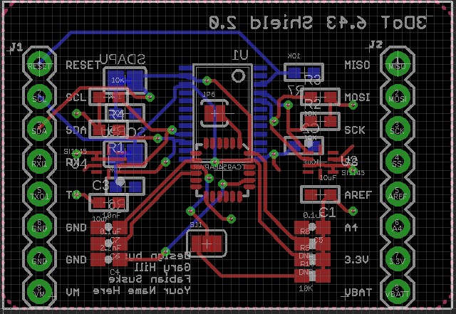
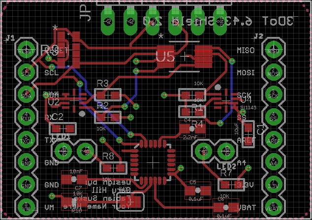
L2 – 6 Main PCB shall have two UV sensors, UV LED, Gyro, and connectors to range finder. Goliath L1-6

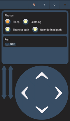
L2 – 7 Arx-robot App will have different operating control modes and direction pad to control Goliath’s

          movement. Goliath L1-6

L2 – 8 Goliath shall have 4 x 10 mm cut out on back of goliath to provide access to charging and

          programming hookup. Goliath L1-5

L2 – 9 The Goliath will not have any electrical parts mounted outside. General Level 1-7

L2 – 10 The Goliath should have a latched lid. Interlocking mechanism. General Level 1-8

L2 – 11 The goliath shall detect objects in an 10 inches in front. Goliath L1-8

L2 – 12 Goliath will have all-terrain tracks. Goliath L1-1

L2 – 13 The goliath shall have 10 gears. Goliath L1-1

L2 – 14 The goliath shall have 2 motor(s), located in the back of the chassis. Goliath L1-1


System Block Diagram

Written by Ryan Nguyen (MST Engineer)

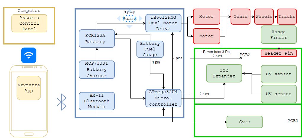
Figure 1 – System Block Diagram for the Goliath Tank.

The system block diagram illustrates how components of the Goliath communicate and connect with each other; from the control panel that uses Wi-Fi to talk with the mobile app to the wheels and treads. More detailed specific components such as the HM11 Bluetooth model is added, and various parts on the PCB parts are laid out; more items are expected when the E&C engineer completes trade off studies. The 3DoT board houses a rechargeable battery that powers the motor driver and the Atmega32U4, which in turn powers the PCB. Number of pins are listed to demonstrate a rough idea of how many pins are required and create rough layout for the interface matrix.

Work Breakdown Structure

Written by Ernie Trujillo (Project Manager)

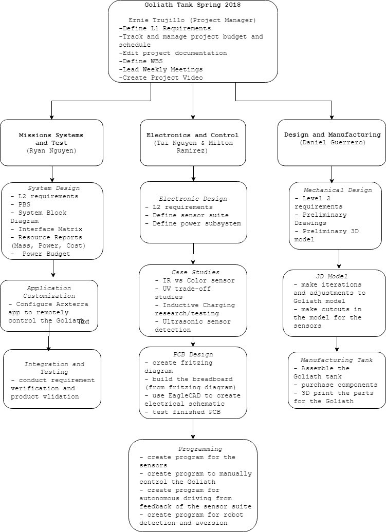
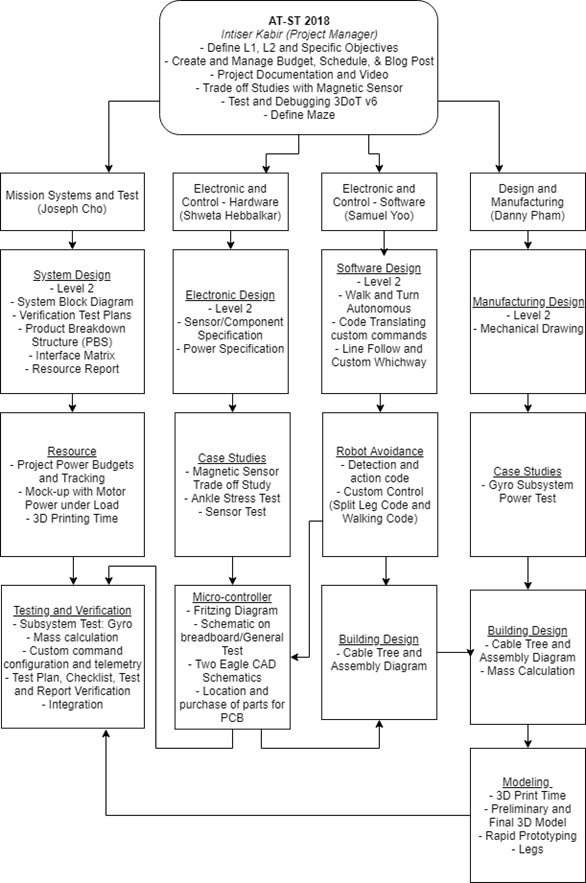
Figure 2 – Layout for the Work Breakdown Structure of the team members.

The Work Breakdown Structure (WBS) provides organization for the tasks a team is required to complete for a project. For the Goliath team, the WBS offers a general overview of the objectives that every team member is required to do. The tasks are broken down in terms of the type of engineer (MST, E&C, and M&D) and then within each field it goes into further detail as to what each position’s tasks entail. This diagram offers each engineer a quick overview of the responsibilities that their position takes on.

Product Breakdown Structure

Created by Ryan Nguyen (MST Engineer)

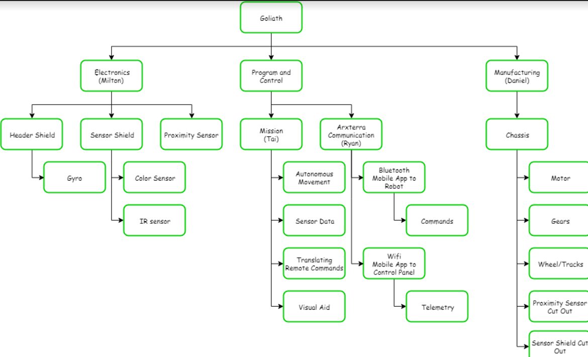
Figure 3 – Diagram of the Product Breakdown Structure.

Like the Work Breakdown Schedule, the product breakdown schedule breaks down the products and the personnel responsible for them. In the spring 2018 project, the Goliath is broken into three products: Electronics, Program and Control, and Manufacturing. All components such as shields and sensors are the responsibility of Milton, as they go on the custom PCB. Tai creates the programs for movement and ultimately completing the mission. Ryan takes care of the communication between the mobile App, control panel, and robot. Lastly, Daniel fabricates the Goliath.


Interface Matrix

Written by Ryan Nguyen (MST Engineer)

The interface matrix shows how each subsystem of Goliath connect to the ATmega32U4 microcontroller. The top header consists of the sub-systems, the left column has the name and pin number of the ATmega32U4. The matrix maps out how each pin is connected.

From the ATmega32U4, the version 6x 3 dot board specifies 16 pins that students can use for their robots. The first matrix shows the two PCBS of Goliath that will be connected to the three dot board, the top header shield, and the front sensor shield.

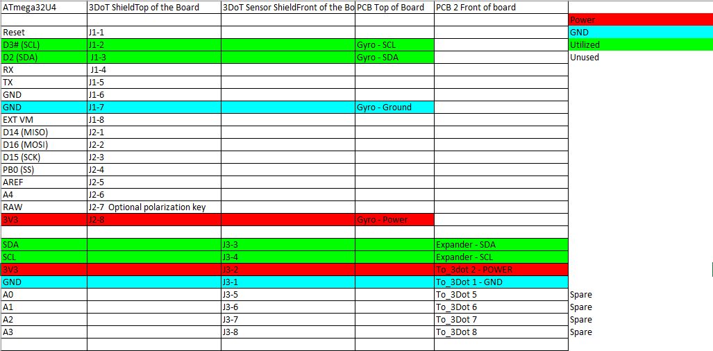
Figure 4 – Interface matrix of ATmega32U4

The second matrix shows how the components on the sensor shield will be connected; Goliath uses two UV sensors, as well as a range finder to navigate the maze.


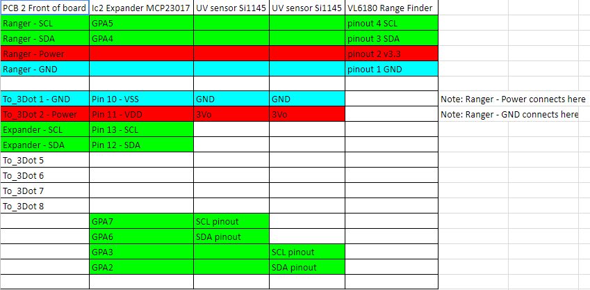
Figure 5 – Interface matrix of front sensor shield

Lastly, Goliath uses a gyro, connected to the top PCB, to determine turning in the maze.

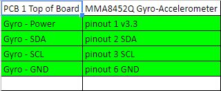
Figure 6 – Interface matrix of top header shield


Fritzing Diagram

Created by Milton Ramirez (E&C Engineer)

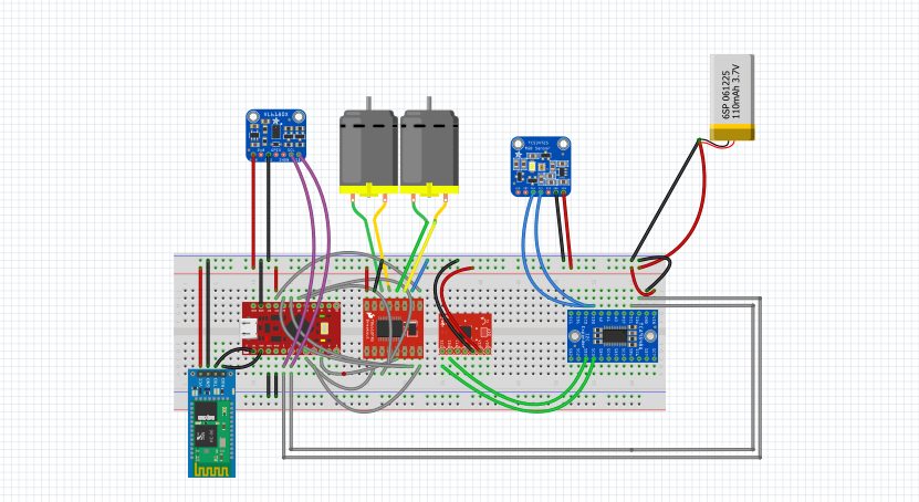
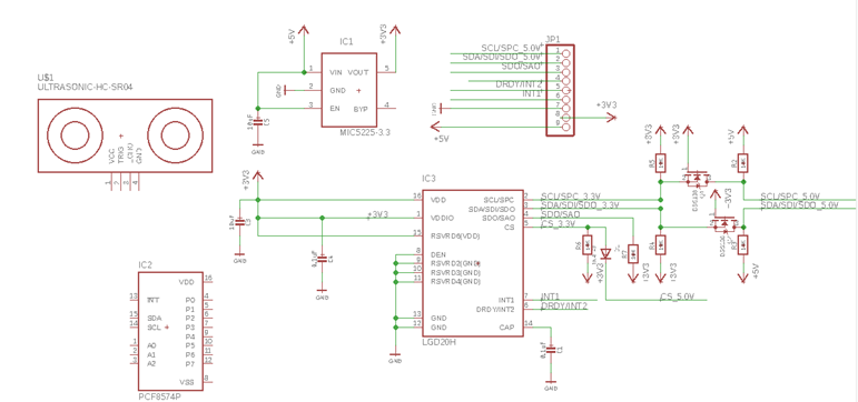
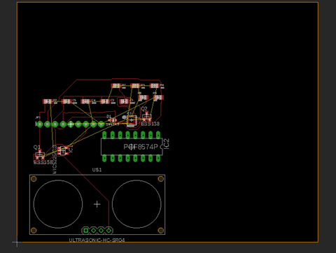
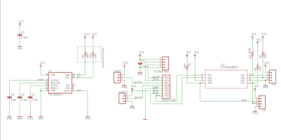
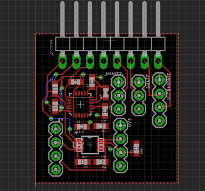
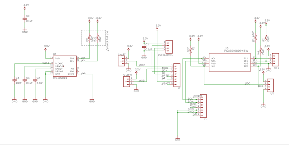
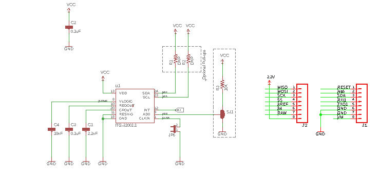
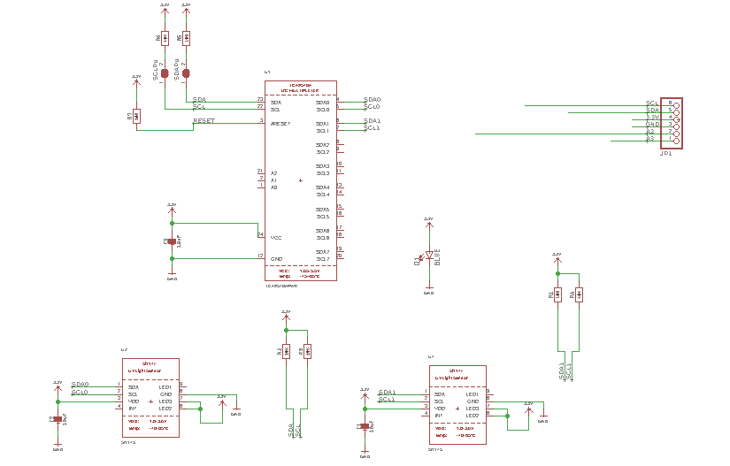
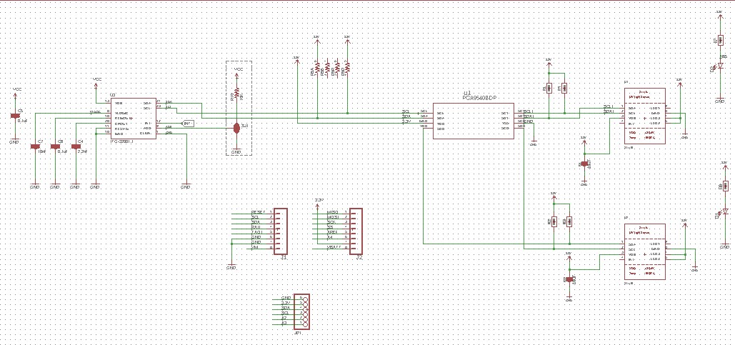
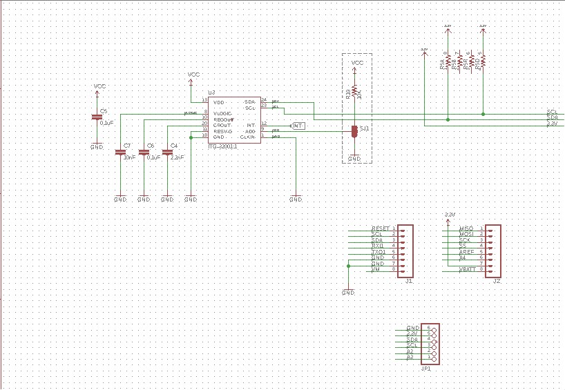
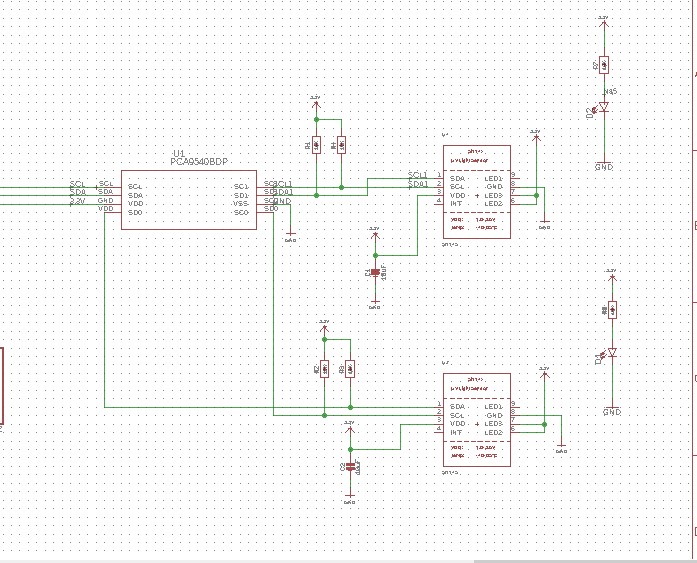
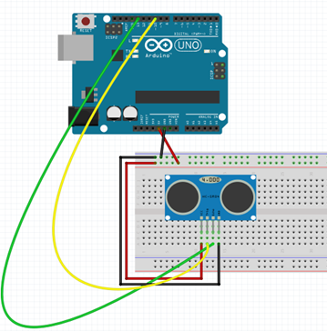
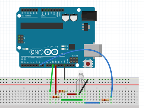
Figure 7 – Fritzing Diagram for the Goliath Tank.

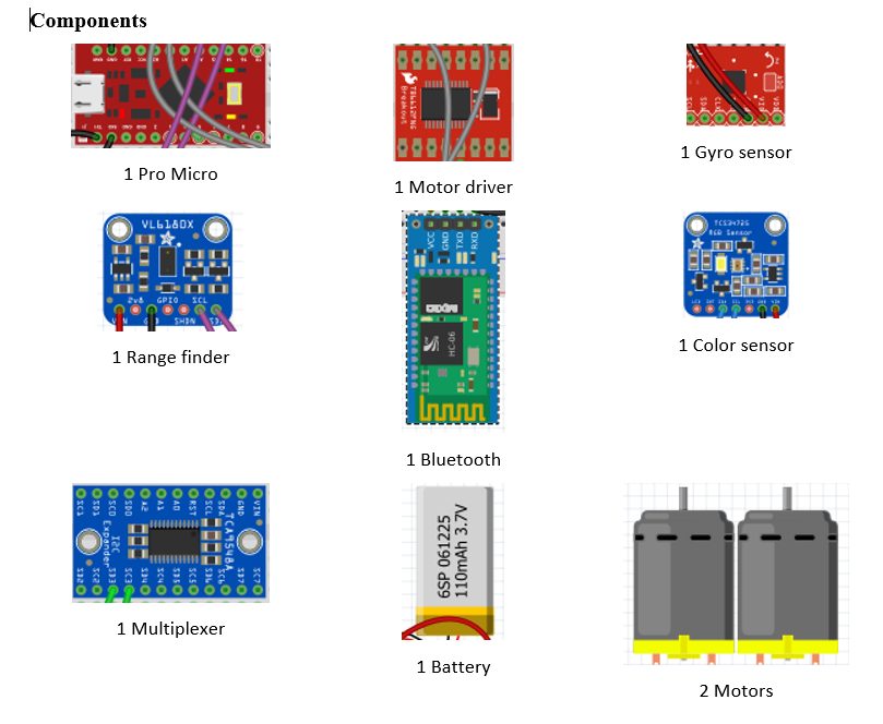
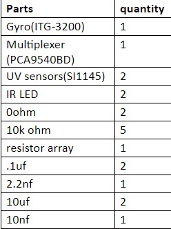
Figure 8 – components used for the Fritzing Diagram.

This a prototype of how we will connect the parts we are going to use and some of these parts might not make the final design. In this prototype our processor will be the pro micro instead of the 3Dot board since Professor Hill is still working on the 3dot board. Also, for that same reason we will have to use Bluetooth circuit for our prototype since the 3dot has Bluetooth implemented in it. We will probably have to use this configuration for most of our testing since we won’t get the 3dot until later in the semester. We also have a motor driver to control our motors. Then we are using a multiplexer for our sensor which are a Gyro sensor and a color sensor. Then we also have a Range finder and this and the color sensor are floating outside on purpose because the color sensor goes in the bottom of the goliath and the range finder we be somewhere in the front. Also the specific part number are not include since that will also change for the last design.


Mechanical Drawings

Written by Daniel Guerrero (M&D Engineer)

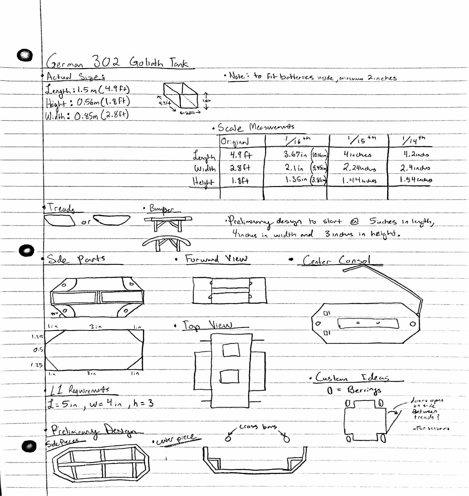
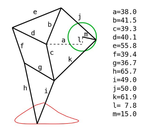
Figure 9 – Preliminary sketches for the Goliath Tank.

The reason behind this design was to follow the concept of the spring 2016’s design to create a box shell of the tank as a preliminary design and attempt to fit all of the equipment inside. I tried to steer away from just a simple box for this design and tried to follow the generic shape of the German 302 goliath tank. As for the placement of all the gaps in this design, I was aiming to have it accessible enough to configure all of our equipment into the design. For this first edition I kept the size to five inches in length by four inches in width and about three inches in height.

Resource Reports (Power, Mass, Cost)

Written by Ryan Nguyen (MST Engineer)

Power Report

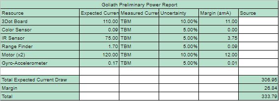
Figure 10 – Spreadsheet for the power consumption of the components.

The power report needs more information in measuring the power draw, this will be done once some sort of system is established for parts such as the 3Dot board and motors. Sensors’ measurements are from data sheets that manufacturer provide. Project allocation comes from the maximum instantaneous current the RCR123A can provide.

Mass Report

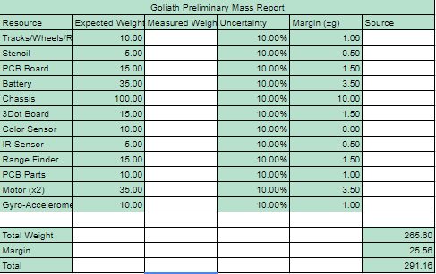
Figure 11 – Spreadsheet for the mass of the components.

Much of the mass report are assumptions, based on visual inspection of parts online. Many parts do not list the mass, such as sensors. It is decided to put 10% margins on all parts as they could fluctuate once the product solidify. Project allocation was based on a requirement that the Goliath shall withstand all impact with all robots; thus the chassis must be quite sturdy.

Cost Report

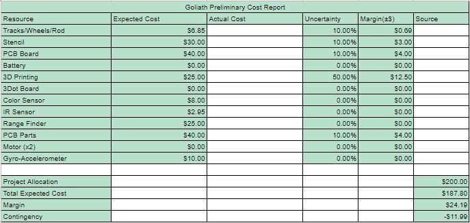
Figure 12 – Spreadsheet for expected expenditures for the Goliath Tank.

The cost report was based from the previous projects, with large uncertainty placed on 3D printing as it is undetermined how many iterations will be printed. Several items are free as they are provided by the class, others are taken from online. Shipping price are considered in uncertainty. Project allocation of $200 dollars was given by the mission objective to make a relatively cheap toy.

Preliminary Budget

Written by Ernie Trujillo (Project Manager)

The customer allotted $200 towards the Goliath Tank project. At this moment, the total expenditure of the project can not be confirmed as the cost for the PCB and the 3D prints designs are unknown. Also, since the definitions of the maze are not complete at this moment, there is a chance that some sensors will be added to the list while others are removed. About 60% of the budget has been established while the remaining funds will be used for the last few parts that will be needed to complete the Goliath Tank.

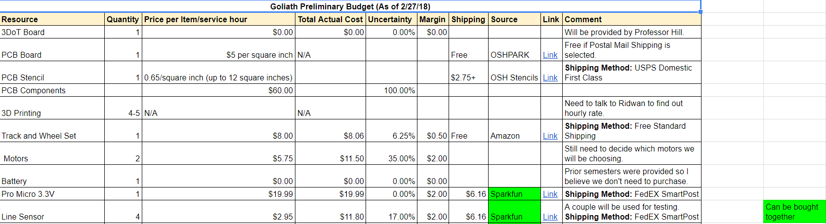
Figure 13 – Excel spreadsheet for the components needed for the project. (1/2)


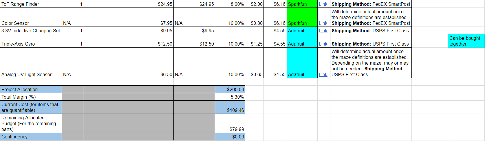
Figure 14 – Excel spreadsheet for the components needed for the project and totals and general overview of the project budget. (2/2)

The spreadsheet provides most of the parts that will be required for mission success. (Will be updated to include all the parts) Included is useful information to the team such as the quantity, cost, and link to the part.

Planning & Schedule

Written by Ernie Trujillo (Project Manager)

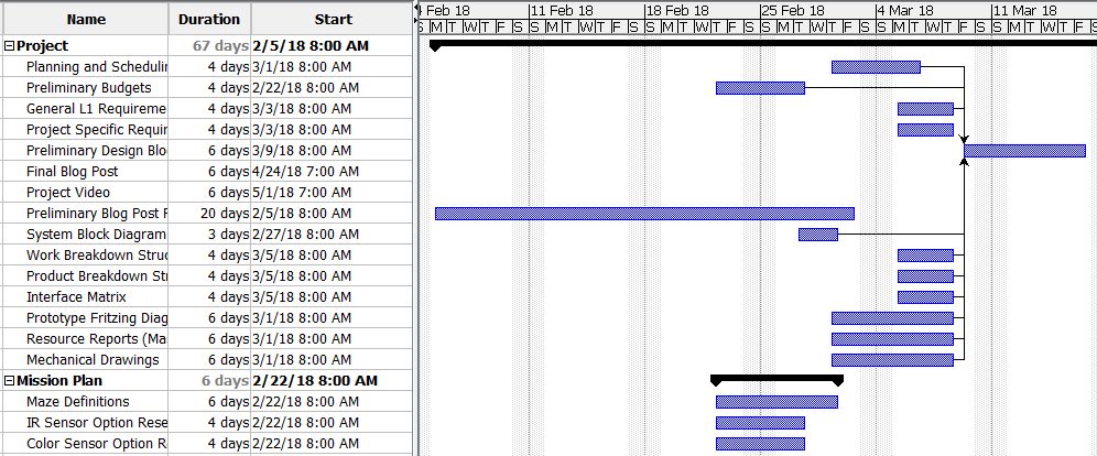
Figure 15 – Gantt Chart , these tasks mainly focus on being prepared for the Preliminary Design Review. (1/3)


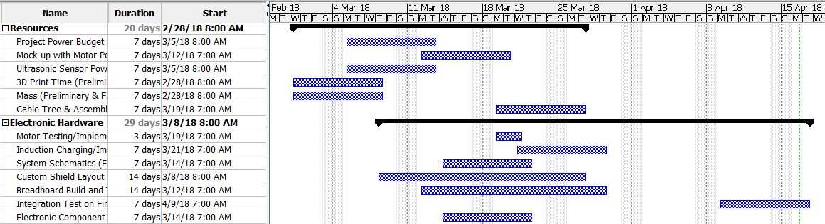
Figure 16 – Gantt Chart (2/3), tasks that are pertinent to implementing the hardware to the Goliath.


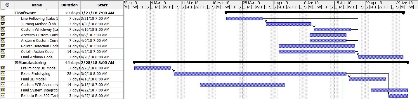
Figure 17 – Gantt Chart (3/3), tasks that focus on software implementation and final verification of the Goliath.

Broad Layout of Project Schedule

Phase 1 (Research), Weeks 1-5:

  • Look through blog posts from prior semesters on Arxterra website for useful information that the current team can implement.
  • Begin developing level 1 & 2 requirements to meet mission objectives and customer expectations.
  • Begin layout for all tasks required to reach mission success at the end of the 16th

Phase 2 (Preliminary Design Review), Weeks 6 – 8:

  • Achieve a thorough schedule to lay out all tasks required to be complete by the team to bring the project to fruition.
  • Accomplish preliminary tasks: preliminary 3D model, system block diagram, fritzing diagram, mechanical drawings, resource reports, work and product breakdown structure.

Phase 3 (Rapid Prototyping), Weeks 9 – 12:

  • Design multiple iterations of Goliath Tank to make final product more efficient.
  • Create program that will integrate all systems that are in the system block diagram. Also, ensure that the program will have the robot operate in a manner that meets mission objectives.
  • Have E & C Engineer work on creating and finalizing custom PCB.
  • Have MST Engineer work on Arxterra custom command and telemetry (Application side)

Phase 4 (Final Product & Mission Success), Weeks 13 – 16:

  • Finalize Goliath Tank 3D model and ensure that all systems are working properly.
  • Complete Project Video that shows progression of project and implementation of the Engineering Method.
  • Complete Final Blog Post which displays a comprehensive overview of the Goliath project from start to finish.
  • On the day of the Final, demonstrate that the Goliath can navigate through the maze and meet all the L1 & 2 requirements.

Summary of Experiments done / Rapid Prototyping Completed

E&C Software Summary Progress

Written by Tai Nguyen (E&C Software Engineer)

  • In progress of setting up pins to be compatible for the 3DoT Board, currently only set up to use with Pro Mico 3.3v
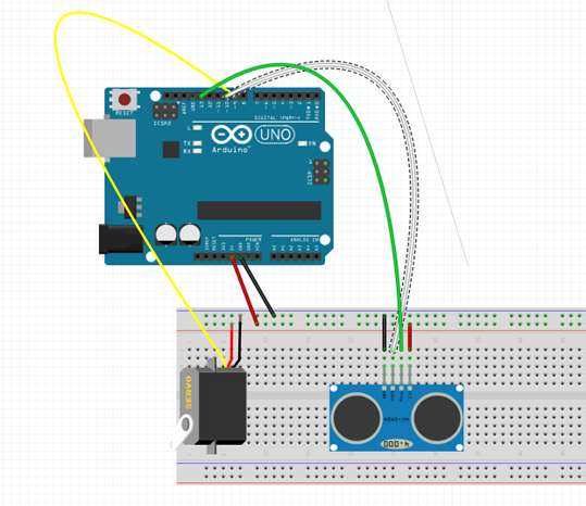
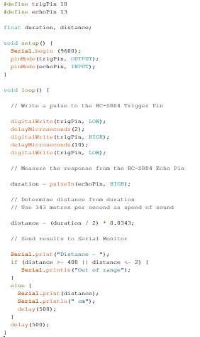
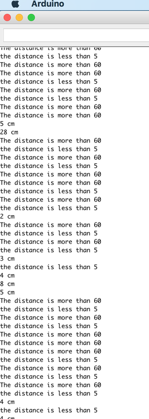
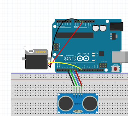
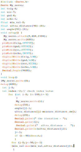
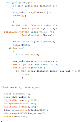
  • I have the ToF Range finder code set up and am working on integrating it into the main code and eventually how it will play into the robot avoidance strategy.
  • Using a mixture of previous Goliath Code and my own input from the gyro I worked with EE 444 for turning, has yet to work properly, needs better calibration code and play testing.
  • Line following code for IR sensors is ready to use if desired.
  • Working on learning the UV sensor based on the recent blog post research by morning section
  • Color sensor research has been put on hold until UV sensor has either been chosen or rejected by the team.
  • Have yet to work with motors in terms of applying the code as well as characterization

3D Model Simulink Prototypes

Written by Daniel Guerrero (M&D Engineer)

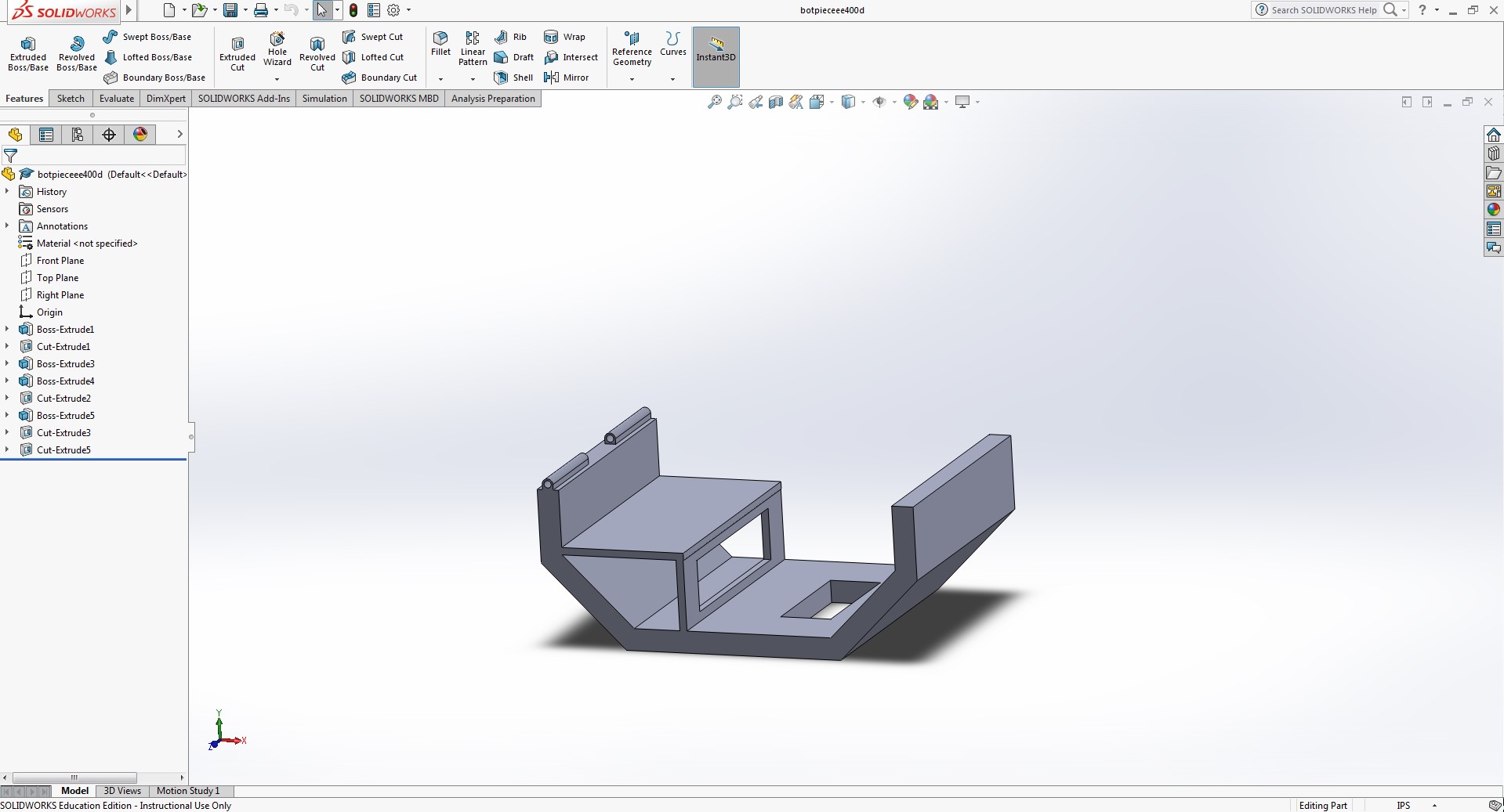
Figure 16 – Bottom piece of the center console.

The reason for this design is to add a base for the rear motors to sit on while also providing space underneath to fit any other electrical components we might have. For the hole at the bottom, we weren’t sure if we were going to continue the line following maze, so I created a hole at the bottom to accommodate for a line following sensor if needed. Also created a hinge like part to the rear of the bottom piece to connect with the top portion to mimic a closing feature.

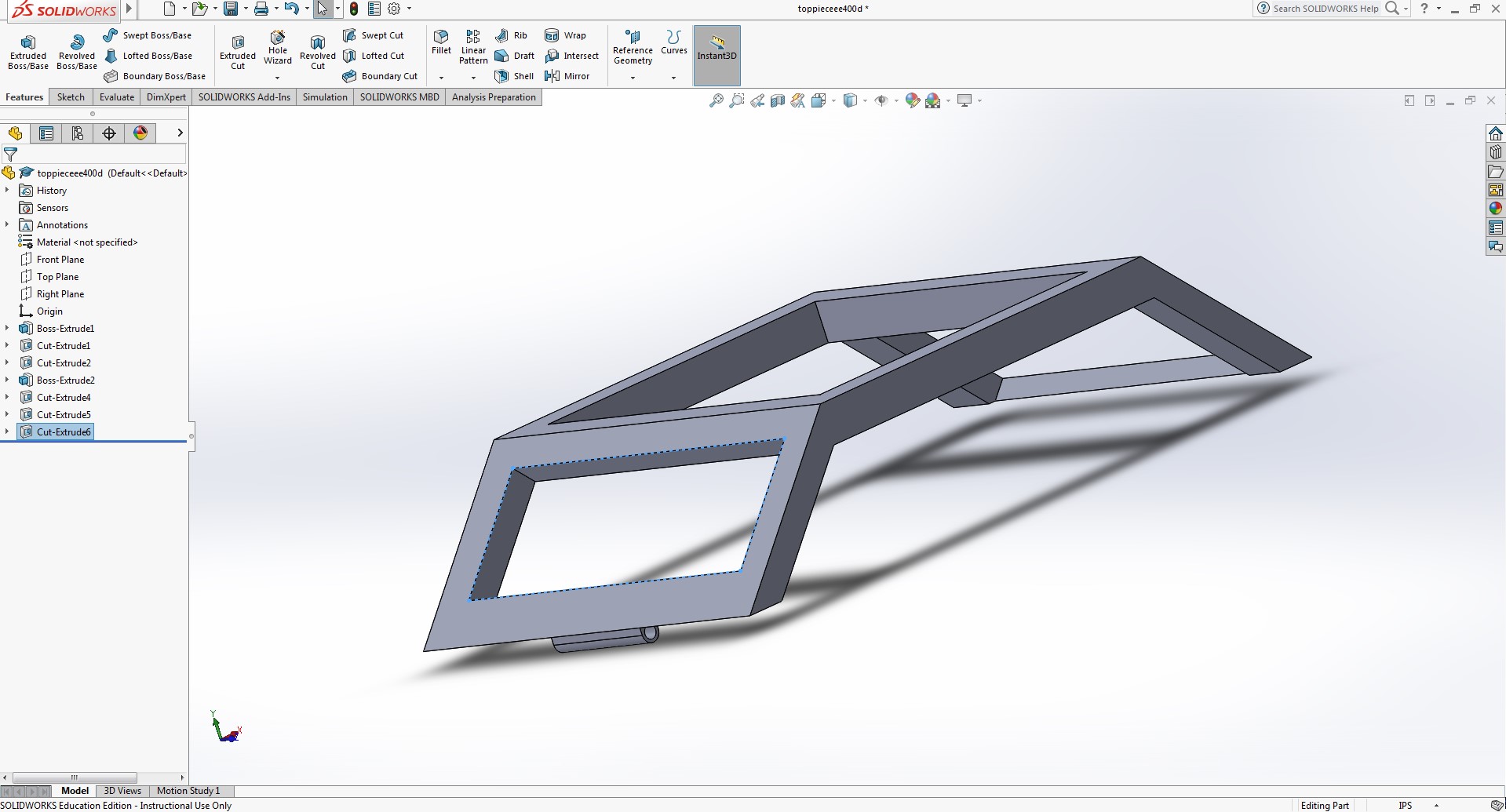
Figure 17 – Top piece of the center console.

Like the side pieces i wanted to keep the tank open until we figured out all the components in the tank. also added the connecting hinge to bottom portion of the tank.

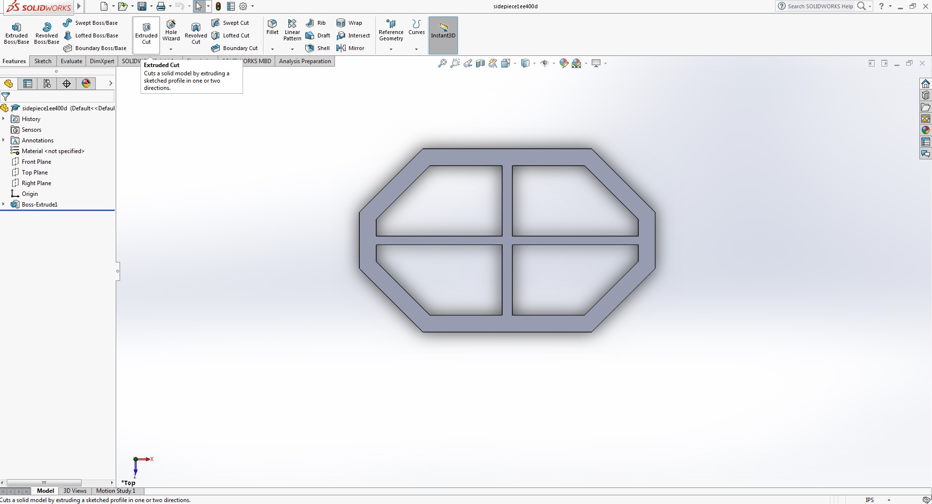
Figure 18 – Side piece for the Goliath.

Wanted to maintain an open design to freely move the parts where ever needed. Made the perimeter thicker than the previous model to be sturdier and be able to screw the pieces together if needed.

Resources

  1. www.arxterra.com/goliath-fall-2017-final-blog-post/
  2. www.arxterra.com/preliminary-design-document-2/
  3. http://web.csulb.edu/~hill/ee400d/Lectures/Week%2001%20Company%20and%20Mission/c_Job%20Descriptions.pdf
  4. https://docs.google.com/spreadsheets/d/19V-HOCEmgzXqFk2eOJVdiPhIjCBXNKYeMXI5y_aF87E/edit#gid=0
  5. Pro Micro
  6. I2C Expander
  7. https://www.arxterra.com/initial-design/
  8. https://docs.google.com/spreadsheets/d/15eEC1hPg-atkorm0VIFIhtkroHR1IgFu7A8-NwoKVB0/edit#gid=0
  9. https://docs.google.com/spreadsheets/d/1X2e8fMk9zH4d6ugtWx0KzsvcbpDvAjY_uL_h4tcDotE/edit
  10. https://www.projectlibre.com/
  11. ToF Range Finder 
  12. https://docs.google.com/spreadsheets/d/1F9hwY03QBFUImZ_wKt4pEAWqgT7hq6SKrcHJS8AYq6I/edit#gid=1180904142

Spring 2018 AT-ST Sensor Testing

By: Shweta Hebbalkar (Electronics and Control – Hardware)

Verified By: Intiser Kabir (Project Manager)

Approved By: Miguel Garcia (Quality Assurance)

Table of Contents

Ultrasonic sensor – HC-SR04

Introduction

As the name implies this device uses an ultrasonic sound to measure the distance between itself and the nearest solid object. Like if we take the nature’s example then it would be like Bats detecting shapes from the sound. So with this key feature has become a staple in our projects because the last thing we want is for our project AT-ST to get the pushed out from the other robots.

Features

  • Operating Voltage: 5V DC 
  • VCC  = 5 volt power connection
  • Operating Current: 15mA
  • TRIG = trigger pin (input) 
  • Measure Angle: 15°
  • ECHO = Echo pin (output)
  • Ranging Distance: 2cm
  • 4m – GND = Ground

Theoretical Explanation of the ultrasonic sensor

Let’s look in more depth of this ultrasonic sensor so for our project we are using the HC-SR04 and it consists of two ultrasonic transducers one is used as the transmitter and another one is used as a receiver. Now when we normally operate the transmitter sends out a series of ultrasonic pulses remember the receiver despite its proximity does not pick up these pulses because ultrasonic signals are very directional. However, if an object in front of the device it will reflect the signals back to the receiver. The time delay that takes from the transmission and receiving the signal is used to calculate the distance so, for example, a longer delay will be considered as long distance and the shorter time delay will be the shorter distance. Now if we send the 5-volt, 10-microsecond pulse to the device then transmits 8 ultrasonic pulses either at the 40-kilohertz each. The echo pin will output a pulse between 100 and 50 – microsecond to 25 milliseconds and that pulse width is used to calculate the distance it will output a pulse of 38 milliseconds if there is no object detected.

Calculating the distance

To determine the distance ultrasonic signal travel at the speed of sound at 20 degrees Celsius the speed of sounds is 343 meters per second now remember the time we’re measuring with the HC-sr04 is for return trip so we’ll need to divide this in half to calculate the actual distance.

∆t=time delay

c=speed of sound (cm)

D=Distance Measured

D=∆t2*c  

As an example

D= (500/2) * 0.0343 = 8.575 cm

Experiment

Figure 1: Fritzing diagram with the Ultrasonic Sensor.

Code

Figure 2: Screenshot of the code

Output

Figure 3: Data from Arduino

Servo – Ultrasonic #1

Introduction

Servos are combined with the motor and also control electronics; this combination makes an easy to use package. The PWM signals with a periodic time of 20 milliseconds and a duty cycle of one to two milliseconds so five to ten percent. While an on time of one millisecond resents the -90-degree position of the motor shafts. 0-degree positions and the 2 milliseconds the +90-degree position. So we can rotate the shaft a total of 180 degrees. 

Features

  • Voltage: 4.8~6.0V
  • Torque: 3.5kg.cm@4.8V, 4.8kg.cm@6.0V
  • Speed: 0.17/60ТА @4.8V;0. 14/60ТА @6.0V
  • Size: 38.6×18.8×34.9mm
  • Wight: 37 g
  • Use Angle: <=160ТА

Figure 4: Fritzing diagram

Code


Figure 5: Screenshot of code

Output

Figure 6: Arduino output

Servo – Ultrasonic #2

Introduction

In this experiment, I created an object detector. So this module will scan from 0 to 180 degrees, and once its finish scanning the module will point at the object. If I displace the object, then the module will scan again from 0 to 180 degrees and trying to look for an object. This is one of the ideas for our project trying to avoid the other robots from the maze.

Fritzing diagram

Figure 7: Fritzing Diagram showing Servo and Ultrasonic

Code


Figure 8: Screenshot of code

Figure 9: Screenshot of code cont.

Output

Figure 10: Physical Demo of Servo and Ultrasonic

RGB led  

Introduction

Formerly, we were going integrate the color sensor to our robot. In order to require the decision either to take right, left, or keep going forward. Now, the color sensor is not required for our project because we change our maze requirements. But before that, I am going to explain the RGB Led to help me understand the color sensor little better. So, an RGB LED is a three LED’s in one basically 4 LED. This is a basic experiment to learn new circuit components and new programming skills.

Figure 11: RGB light connections on using fritzing diagram

Code

Figure 12: Screenshot of code

Output

Figure 13: The RCB displaying 3 different colors

Dc Motor

DC Motors that operate on direct current as opposed to motors, which operate on alternating current. We are using the small dc Motors for our project in order to move let’s look into how dc motor works. The shaft of the motor, the part that rotates is referred to an armature. On the armature, there are coils of wire these coils are connected to the commutator. The connections to the commutator are called the brushes, where the positive and negative voltage is applied. On the outside of the motor, there is a permanent magnet arranged in opposite magnetic polarity, now when dc current is applied to the commutator it sets up a magnetic field inside the coil. The coil magnets interact with permanent magnets causing the armature to rotate, now as the armature rotates the polarity is continually reversed generating the magnetic field to be reversed and the rotations to continue.

A motor driver module helps the dc motor with an Arduino, which means that dc motor will get the more current in order to, work, in other words, a current amplifier. So a motor driver is a breakout board, which consists of an L293D IC, the main purpose of the motor driver is to take a low current signal and convert it to a high current signal.

Conclusion

Due to some feedback from the Professor, we are not using RGB and will be using UV sensors with IR LEDs. We are using Ultrasonic as an avoidance mechanism. The DC motor is used to move our legs. We are planning to use servos to help control the center of gravity.

Reference

  1. https://cdn.sparkfun.com/datasheets/Sensors/Proximity/HCSR04.pdf
  2. https://www.sainsmart.com/products/ultrasonic-ranging-detector-mod-hc-sr04-distance-sensor
  3. https://components101.com/ultrasonic-sensor-working-pinout-datasheet
  4. https://www.radioshack.com/products/radioshack-standard-servo
  5. https://www.sparkfun.com/datasheets/Components/YSL-R596CR3G4B5C-C10.pdf
  6. https://nationalmaglab.org/education/magnet-academy/watch-play/interactive/dc-motor