Spring 2018 AT-ST Shaft Encoder

By: Joseph Cho (Mission, Systems, and Testing)

Verified By: Initiser Kabir (Project Manager)

Approved By: Miguel Garcia (Quality Assurance)

Table of Contents

Introduction

For our AT-ST project, the two motors on the legs have to be precise. In order to know the exact location of the turns, shaft encoders have to be added. The shaft encoders that have been chosen will be using a magnetic shaft encoder. The magnetic shaft encoder uses hall effect to determine the rotation of the axle.

Hall Effect

The shaft encoder is packaged with a 6 pole magnetic disk that is used to provide the magnetic field. Hall effect is observed when magnetic field causes the small current of elections to deviate and produce Hall voltage. When the magnetic disk rotates, it causes changes in magnetic fields. The hall effect latch (TLE4946-2K) inside the shaft encoder will sense these changes and output values. Using these output values, the position of the axle will be determined.


Connections on shaft encoder

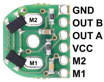
Figure 1: Connections on shaft encoder

Description:

The shaft encoder has 6 pins. The M1 and M2 pins on the right are for powering the motor. The motor will be connected directly to the shaft encoder by soldering M1 and M2 holes in the center of the board. GND and VCC are used for powering the board. Output A and Output B are the outputs from the two TLE4946-2K hall effect latches.

After contacting the previous blog post author, the decision to use only one of the output has been made. The shaft encoder has two hall effect latches for accuracy and using only one of them is sufficient enough for our uses. A trade-off study may be done to test the amount of current used and the accuracy of the shaft encoder.

GearMotor with Shaft Encoder

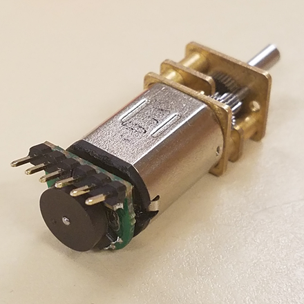
Figure 2: GearMotor with Shaft Encoder

The image above shows that the shaft encoder is soldered onto the motor directly with male headers.

Schematic of Shaft Encoder

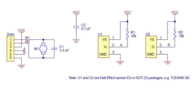
Figure 3: Schematic of Shaft Encoder

Description

The schematic shows the connections of the shaft encoder. The motor will be soldered onto M1 and M2 which will be powered by pin 1 and pin 2 of the shaft encoder. Pin 3 and pin 4 are used for Vcc and Ground. Pin 4 and pin 5 are outputs of the shaft encoder hall effect readings.

Reference

  1. https://www.pololu.com/product/3081/specs
  2. https://www.pololu.com/file/0J814/magnetic-encoder-kit-for-micro-metal-gearmotors-schematic.pdf
  3. https://www.pololu.com/file/0J815/TLE4946-2K.pdf
  4. https://www.arxterra.com/motor-shaft-encoder-trade-off-study/
  5. https://www.electronics-tutorials.ws/electromagnetism/hall-effect.html
  6. https://www.pololu.com/product/3081/specs#lightbox-picture0J6835;main-pictures

Goliath Spring 2018 – Work Breakdown Structure

By: Ernie Trujillo (Project Manager)

Approved By: Miguel Garcia (Quality Assurance)

Figure 1 – Diagram for the Work Breakdown Structure of the Goliath Team members.

The Work Breakdown Structure (WBS) provides organization for the tasks a team is required to complete for a project. For the Goliath team, the WBS offers a general overview of the objectives that every team member is required to do. The tasks are broken down in terms of the type of engineer (MST, E&C, and M&D), and then within each field, it goes into further detail as to what each position’s tasks entail. This diagram offers each engineer a quick overview of the responsibilities that their position takes on.


Goliath Spring 2018 – Product Breakdown Structure

By: Ryan Nguyen (MST Engineer)

Verified By: Ernie Trujillo (Project Manager)

Approved By: Miguel Garcia (Quality Assurance)

Figure 1 – Diagram of the Product Breakdown Structure.

Like the Work Breakdown Schedule, the product breakdown schedule breaks down the products and the personnel responsible for them. In the spring 2018 project, the Goliath is broken into three products: Electronics, Program and Control, and Manufacturing. All components such as shields and sensors are the responsibility of Milton, as they go on the custom PCB. Tai creates the programs for movement and ultimately completing the mission. Ryan takes care of the communication between the mobile App, control panel, and robot. Lastly, Daniel fabricates the Goliath.

Goliath Spring 2018 – Preliminary Resource Report

By: Ryan Nguyen (MST Engineer)

Verified By: Ernie Trujillo (Project Manager)

Approved By: Miguel Garcia (Quality Assurance)

Figure 1 – Spreadsheet for expected expenditures for the Goliath Tank.

The cost report was based on the previous projects, with large uncertainty placed on 3D printing as it is undetermined how many iterations will be printed. Several items are free as they are provided by the class, others are taken from online. The shipping price is considered an uncertainty. Project allocation of $200 dollars was given by the mission objective to make a relatively cheap toy.

Figure 2 – Spreadsheet for the mass of the components.

Much of the mass report are assumptions, based on visual inspection of parts online. Many parts do not list the mass, such as sensors. It is decided to put 10% margins on all parts as they could fluctuate once the product solidified. Project allocation was based on a requirement that the Goliath shall withstand all impact with all robots; thus the chassis must be quite sturdy.

Figure 3 – Spreadsheet for the power consumption of the components.

The power report needs more information in measuring the power draw, this will be done once some sort of system is established for parts such as the 3Dot board and motors. Sensors’ measurements are from data sheets that manufacturer provide. Project allocation comes from the maximum instantaneous current the RCR123A can provide.

Goliath Spring 2018 – Preliminary 3D Model

By: Daniel Guerrero (M&D Engineer)

Verified By: Ernie Trujillo (Project Manager)

Approved By: Miguel Garcia (Quality Assurance)

Figure 1 – Preliminary design for the center console of the Goliath.

The latest design created came out as one piece to print, but as I add walls and other portions of the tank, that will change. I’ll begin by dividing the tank into 4 sections; the 2 side walls, the center bottom portion, and the center top portion. When creating the next design I’ll also be adding the side box features and possibly use them as storage or placement for sensors or other electrical components implanted into our project.

For the upcoming designs I’m planning to stay close to the overall shape of this design but accommodate for the equipment being placed inside and adding the side features to the original 302 goliath tank between the treads. I’ll also aim to get closer and closer to the 1/16 scale model of the actual tank. Currently, I am also researching design concepts to creating a closing feature to the center console of the tank that will have a hinge at one end and allow the top hatch to open and close completely.

Spring 2018 AT-ST System Block Diagram

By: Joseph Cho (Mission, Systems, and Testing)

Verified By: Initiser Kabir (Project Manager)

Approved By: Miguel Garcia (Quality Assurance)

Table of Contents

Introduction

The system block diagram is made to visually show the systems of our product, AT-ST. The 3DoT board is the center of the system consisting the microprocessor and motor headers. There will be custom PCB that are connected to the 3DoT board for telemetry and sensors.

System Block Diagram

Figure 1: System Block Diagram


Description

The System block diagram above for AT-ST help visualize the system of the AT-ST.  The 3DoT board uses ATmega32U4 as the microcontroller. The 3DoT board consists of microcontroller, bluetooth transceiver,  servo header and dual motor driver. The 3DoT board (v6) will also be connected to the servos, motors and main custom PCB. PCB1 will be the master PCB that routes all input and output for the sensors. PCB 2 and PCB 3 are used for UV sensors which will be connected to the I2C expander on PCB 1. Bluetooth transceiver will connect to a mobile device using the Arxterra app via bluetooth.

I2C Expander

The UV sensors has to be connected to the I2C expander because the I2C address of same sensors will be overlapping. If we were to use a metaphor of I2C addresses, they are different phone numbers that are used to communicate. If two people were to have the same phone number, there would be a major problem. Signals may be overlapped, misguided, and destroyed when the addresses overlap each other.  The I2C address of the Si1145 (UV sensor) is set on 0x60, so I2C expander has to be used to change the single address into two different addresses. One thing to be cautious about is that the new address should not overlap the address of gyroscope (0x68 or 0x69).


References

  1. https://www.arxterra.com/fall-2017-velociraptor-preliminary-design-document/
  2. https://learn.adafruit.com/i2c-addresses/the-list

Spring 2018 AT-ST Line Follower Code

By: Samuel K. Yoo (Electronics & Control – Software)

Verified By: Intiser Kabir (Project Manager)

Approved By: Miguel Garcia (Quality Assurance)

Table of Contents

Introduction

The main objective of this code is to make the robot follow a line. The initial part of the program has two motors turning wheels to move forward. After accomplishing this first part of the code, the next is to create the line follower. There would be four sensors not touching the line, and if the sensor hit the line, the robot would swerve away and continue to head straight. The AT-ST would not use motors for forwarding motion, instead, it uses servos. The four sensors will still be the same for the AT-ST.

Code

Figure 1: Code Screenshot

Figure 2: Code Screenshot cont.

Explanation

The beginning of the code initializes all the pin definitions and the I/O for each pin.  After that part of the program, the main loop contains the movement code. This code allows two motors to spin in opposite directions, attached to the wheels to move the robot forward. However, this movement code will be modified at a later date, as the AT-ST uses servos. The servos do not work like the motors and require a lot more analog pins. These pin requirements will need an analog extension. The sensor reading code, however, can mostly stay the same. The concept of slowing one part and increasing the speed of the other part will stay the same. However, it would not be the torque but the movement of the leg. Another huge difference in the code is the values. If this program would run on a robot right now it would crash or not move straight at all. This is because each motor is made with different values. There is no minimum value for the speed and the delay values might be too long.

Conclusion

So this line code main purpose is to move the robot forward and to follow a line. One of the issues is the AT-ST does not use motors for movement, it instead uses servos, which at the moment of this blog post, there is no research on. Another issue is the values inside the code are not accurate. These values need to be tested in real life to get value for the code. Overall, the general idea of the code in this blog post, however, needs to be updated with servos code and the real values in the final code.  

Spring 2018 AT-ST Power Budget

By: Joseph Cho (Mission, Systems, and Testing)

Verified By: Intiser Kabir (Project Manager)

Approved By: Miguel Garcia (Quality Assurance)

Update: Figures have been updated to measured values.

Table of Contents

Introduction

Power budget of the AT-ST project will be estimated using the power budget general template. The power budget will be estimated to determine the battery that should be used on the AT-ST. All of the values used in the power budget are measured using a current meter.

List of Parts

This is the list of all of the parts we are using as of today!

  • 3DoT Board
  • Bluetooth: HM11
  • Dual Motor Driver: DRV8835
  • (2) Motor: 50:1 Micro Metal gear motor
  • (2) Servos: HTX900
  • (2) Shaft Encoders : Pololu product 3081
  • I2C Expander: TCA9548A
  • Gyro : GY-521 (MPU6050)
  • Ultrasonic: HC-SR04
  • IR LED 1 (rated for 16~18mA)
  • Light sensor 1: Si1145
  • IR LED 2 (rated for 16~18mA)
  • Light sensor 2: Si1145

Power Budget Spreadsheet

Figure 2: The total Power In/Output of the system

Figure 3: Boost Parameters

Figure 4: Margin Calculation

Description

The current design for AT-ST uses 2 motors and 1 servo. The majority of the power is consumed by the motors and servo to move the AT-ST. The motors output power will be distributed by the motor driver. Four sensors will be used: UV, ultrasonic, shaft encoder, and gyroscope. The sensors will be using less power compared to the motors. Based on the estimated current consumption, a general power usage will be estimated using the power budget general template.

Measuring Current

Figure 5: Multimeter used to measure current

Description:

Rigol DM3058E digital multimeter was used to measure the current drawn by the components. The multimeter was tapped between the output pin of the microcontroller and VCC of the sensor.

Resources

  1. https://www.arxterra.com/news-and-eventsmembers3dot-robots3dot-goliath/
  2. https://www.sparkfun.com/datasheets/Components/LED/YSL-R547P4C-E3.pdf
  3. https://docs.google.com/spreadsheets/d/1WsdFps31TaSi-vaA3mB8fVlLQd3yEO-VCvbinQXoAG8/edit?usp=sharing
  4. https://docs.google.com/spreadsheets/d/1OaWtFrqYVQsylEh2nXOvKjFT-g2KG72ej-pF6OJWQ54/edit?usp=sharing

Spring 2018 AT-ST Resource Reports (Mass, Power, and Cost)

By: Joseph Cho (Mission, Systems, and Testing)

Verified By: Intiser Kabir (Project Manager)

Approved By: Miguel Garcia (Quality Assurance)

Table of Contents

Introduction

The resource report contains three parts: Mass report, power report, and cost report). These reports will be covering the resources’ mass, power, and cost. An estimate of the total mass will be shown on the mass report. For power report, the current values were taken from previous projects’ blog posts as reference. Lastly, cost report will show that the AT-ST project is within the budget.

List of Parts

  • 3DoT Board
  • Bluetooth: HM11
  • Dual Motor Driver: DRV8835
  • (2) Motor: 50:1 Micro Metal gear motor
  • (2) Servos: HTX900
  • (2) Shaft Encoders : Pololu product 3081
  • I2C Expander: TCA9548A
  • Gyro : GY-521 (MPU6050)
  • Ultrasonic: HC-SR04
  • IR LED 1 (rated for 16~18mA)
  • Light sensor 1: Si1145
  • IR LED 2 (rated for 16~18mA)
  • Light sensor 2: Si1145

Mass Report

Figure 1: Mass Report


Description:

Comparing our AT-ST to last generation of velociraptor, the mass will be around 800g. 3D printing mass is estimated on the mass report blog post. Since the custom PCB will be made with the same materials with 3DoT board, we can estimate that the mass of the PCB will be similar to the 3DoT board. Our main PCB is slightly smaller and two other sensor PCB are half the size. Further more information about how the masses were estimated and weighed are in Mass report blog post. There are also couple of measured weight as 0. This is due to those parts being included in the body of the mass measurement.

Power Report

Figure 2: Power Report

Description:

The power report shows the expected current draw needed from the power supply. Each servo is rated at 270 mA with a load. The 3DoT board current draw is also counting these parts: Bluetooth and dual motor driver. Measured currents have been added. The motor uses 29mA with load and 170mA when stalled. Power budget was used to determine if a battery with higher capacity was needed.

Link to Power Budget

Cost Report

Final Cost

Figure 3: Cost Report

The cost report shows the total expected cost to be slightly more than half of the budget. After totaling up the spendings, we are still under the budget of $250. There are some components that are given or borrowed; therefore, the actual cost is zero for those items. Our total cost for the AT-ST materials is $199.58 with shipping included.

Extra Cost

Figure 4: Extra costs (included in Cost Report)

Description:

There were additional costs to AT-ST, but not included in final cost report because these resources were not used on the AT-ST.

Conclusion

The reports show that the AT-ST had all resources within the project allocation. The final mass of AT-ST was 256.80 grams, which is very light compared to 2nd generation of Velociraptor. Total cost of the final product was $199.58 and the prices could have been lowered if parts were ordered earlier.

Resources

  1. http://www.custompcb.com/faq.php
  2. https://docs.google.com/spreadsheets/d/1_q0K2hwcqDshcp3e7MT1azD3lbXh80qJeSJ1bALZQZ0/edit?usp=sharing
  3. https://docs.google.com/spreadsheets/d/1P0TaSyV01-3muaii-rDUmqtotstaM6gV4AgC4sjzqFQ/edit?usp=sharing
  4. https://docs.google.com/spreadsheets/d/1j9I_ts227pN5yA5srDkUxOWhMTKYiYWG9uBwJw8IQA8/edit?usp=sharing 

Goliath Spring 2018 – Power Budget

By: Ryan Nguyen (MST Engineer)

Verified By: Ernie Trujillo (Project Manager)

Approved By: Miguel Garcia (Quality Assurance)

Figure 1 – Power Budget for the components of the Goliath.

Version 6.x of the 3DoT board does not include an LDO component, thus several changes were made to the power budget to reflect that change. All of LDO related currents and voltages were deleted, making the template much simpler. To calculate the power budget out the template, current draw of each subsystem must be obtained, by either measurement or data sheets. The template then takes those measurements and calculates the margins of power dissipation, output current, and how long the battery would last. Several assumptions were made, such as the EFFboost, the efficiency of the buck/boost converter, UVLO, FET switch limit, and inductor saturation.

Since Goliath does not use a servo, we won’t have a current draw from it. Regarding margins, there are three that we considered. From top to bottom and left to right: The first is heat safety margin. Our application dissipates 41.62 mW while the max is 971 mW so we are almost 96% safe. The second margin is the boost converter and its supply current margin; boost converter is able to supply plenty of current with a 91% margin. Third, is the margin is maximum instantaneous current the battery can supply, at 1300 mAH, we have a 78.46% margin. Lastly, we have a huge margin on runtime where we are able to operate at 112 minutes, twice the mission duration of 1 hour.