Integrated Control Document

Written by: Luis Martinez

Approved by: Carolina Barrera

The purpose of the Integrated Control Document (ICD) between the Prosthetic Arm and Prosthetic Hand systems, as an integrated Upper-Limb Prosthetic System, is to capture essential categories of interaction between both systems upon their unification. This document details explicit responsibilities and agreements between each of the respective groups, and serves as an approved reference document for both project groups to refer to, as a standard for design objectives shared amongst both groups.

Of key regard amongst shared transactions between both groups are those for power, attachment, mass, size, and volume accommodation. Below is a high-level description of these categories:

Power – The Prosthetic Arm will supply power to the Prosthetic Hand via 3x, 22 AWG cables (12V, 5V, GND), allowing up to 3500 mA on 12V, and 1000 mA on 5V from a 1600-mAh, 14.8-V Lithium-Ion Polymer (LiPo) battery stored in the bicep of the Prosthetic Arm system.

Attachment – The Prosthetic Hand will be responsible for allocation of the wrist, of dimensions 76.2 mm x 76.2 mm ± 12.7 mm (3 in x 3 in ± 0.5 in margin). The mounting interface between both systems will be a squared, plated-screw type consisting of 4x, 4-mm screws and a hollow center, allowing the Prosthetic Arm to feed power cables to the Prosthetic Hand in such a way that they are not operationally inhibited by the rotation of the wrist. Furthermore, the Prosthetic Hand will be responsible for any cabling related to storage of their micro-controller (MCU) and printed circuit board (PCB) components within the Prosthetic Arm portion of the integrated system.

Mass – The forearm, hand, and food sustained by the Upper-Limb Prosthetic System should not exceed a combined weight of 6.83 lbs. to correspond with a torque of 10.634 NM at 35 cm for the stepper motor localized at the elbow by the Prosthetic Arm. From this, the Prosthetic Hand will have an allocation of 1.35 ± 0.23 kg (2.97 ± 0.5 lbs.), with an expected weight for the heaviest food item (21 fl oz. drink) at 0.69 kg (1.52 lb.). Overall, the system should be no heavier than 4.0 ± 0.61 kg (8.82 ± 1.35 lbs.).

Size – The Prosthetic Arm, in conjunction with the Prosthetic Hand should be no longer than 35 cm ± 5 cm (13.78 in ± 1.55 in) from elbow to tip of middle finger, from which the Prosthetic Hand will measure 269 ± 13 mm (10.6 in ± 0.51 in) from end of wrist/ forearm attachment to tip of middle finger.

Accommodation (Volume) – As referenced above, the Prosthetic Arm will provide space accommodations for the MCU, PCB units of the Prosthetic Hand, of dimensions 83 mm x 64 mm x 38 mm (3.25 in x 2.5 in x 1.5 in) in effort to alleviate space constraints faced by the Prosthetic Hand.

After the Preliminary Design Review (PDR), suggestions from the customer and class presidents were taken into consideration by both groups, and agreements were reached with respect to the following new categories:

  • Noise: Prosthetic Arm, in conjunction with Prosthetic Hand, will not exceed 60 dB during operation.
  • Safety: Prosthetic Arm will implement an electronic kill switch to disconnect the power supply to the Prosthetic Hand and the Upper-Limb Prosthetic System in the case of a perceived emergency situation or safety concern.
  • Schedule: Prosthetic Arm and Prosthetic Hand groups will have their respective systems ready for integration by an agreed-upon tentative date of Saturday, 11/19/16
  • Aesthetics: Prosthetic Arm, in conjunction with Prosthetic Hand, will have a matching outer appearance, such that in the case of wearing a sleeve and glove respectively, the Upper-Limb Prosthetic System will not attract unwarranted attention.
icd_2

Prosthetic Arm Overview

Moving forward, certain category estimates will be refined, such as the estimated noise threshold to correlate with experimental studies from a McDonalds site visit, and an integrated temperature sensor in the circuitry of the Prosthetic Arm that will be programmed to detect significant deviations from the operating temperature of the Upper-Limb Prosthetic System once integration has been achieved.

Furthermore, an option to vacuu-form, in terms of aesthetics, is being explored by the Prosthetic Arm system in collaboration with the CSULB Design Department pertaining to guidance and permission to use related facilities and equipment. Further changes to this approved document will be submitted for approval, and captured as supplemental revisions.

Prosthetic System Definition Update

After testing the EMG sensor and a joint meeting with the Hand group, the responsibilities of each E&C division had been set in stone. The decisions of this meeting had been protocolled in meeting minutes as well as on a drawing with each member signed.

fabians1

Figure 1 – E&C Agreement with the Hand

In the following weeks the Level 1 and Level 2 requirements had been finalized and the System Block Diagram could be updated. In the final design two indicator LEDs had been added as well as a Kill Switch. The Kill Switch gives the user the possibility to power off the system (immediately) in the event he doesn’t feel comfortable with the systems behavior.

Also there’s no need to communicate between the two systems anymore so the I2C lines had been removed.

The tests of the MyoWare muscle sensor also came to the conclusion that one motion can be tracked sufficient enough with one sensor. But a second sensor is not enough to provide a second motion. A second motion might be accomplished with a third sensor. Since the Project requirement can be fulfilled with one motion and in regard to the budget only one EMG sensor will be used.

All this led to this updated System Block Diagram.

Figure 2 - Resulting and Updated Block System Diagram

Figure 2 – Resulting and Updated Block System Diagram


Evolution of the Bicep Design

Written by: Forrest Pino

Approved by: Carolina Barrera

The bicep – also  known as the bicep branchii, is a muscle that lies in the upper arm between the shoulder and the elbow. It’s is a structural part that offers sturdiness and strength to the overall upper-arm system. The overall arm works as a lever where the weight of the forearm and the hand are the load, the elbow is the axis or fulcrum and finally the bicep muscle when flexed is the force that will executing a work.

The following is a development write-up of the bicep design done by the manufacturing engineer in the Prosthetic Arm team, Forest Pino.

The first design concept arose from simple measurements and initial brainstorming. I measured the length of my arm and tried to develop a design that would be an adequate length and shape.

The concave nature of the lower section of the bicep was developed after studying other prosthetic arm projects with similar features. The concave feature allows for the forearm to rotate about the semi-circle at the bottom of the design.

A perforated design was conceptualized due to its ability to maintain structural integrity while reducing weight. The prosthetic arm and its various sections are limited by weight so any gaps or features that can reduce the use of plastic will help with weight and cost of the project.

Build Upon Design 1

figure1

Figure 1 – Lateral structure. First iteration of bicep

Triangular and trapezoidal features were added for strength and stability. The initial design did not contain any features that would helping with housing components. At the time, parts were not realized and the design served more as a stepping stone and base for further work.

figure2

Figure 2 – Design 1 Pre-Motor Mount

The cuts on the outer perimeter of the design were developed for braces that would be attaching and providing for structural integrity.

figure3

Figure 3 – Pre-motor Design Lateral Side

These trapezoidal cuts were made as a locking mechanism that would help pieces maintain position and provide for structural integrity. The largest side of the trapezoidal cut was planned to be the outer face of the bicep. This feature would allow interlocking piece to slide in only one direction.

figure4

Figure 4

figure5

Figure 5

figure6

Figure 6

Once a possible motor was selected, an area for mounting began to take shape. The extruded circular cut in the lower half of the bicep was planned to be the area where the motor would be mounted. The shaft of the motor would protrude outward toward the outer face of the bicep. In this design, the arm that would be developed would be on the right and where the gears would line on the outer side of the arm. Originally, the twos gears were thought to be interconnected by a pulley or chain. The possible sizes of the gears were not realized at this point and a cut made for the mounting of the forearm to the bicep could not be produced yet. Having gears on the inside of the bicep or residing between the arm and the body would not be feasible due to the size of the motor and possible interference. The gears were chosen to reside on the outer most part of the arm so that interference from the user would be reduced

figure7

Figure 7

figure8

Figure 8

The first assembly provided a base knowledge into how lightweight the initial design work was and how adding more plastic for the mounting of components may be necessary. The areas where the components may reside were exposed to the surrounding environment and a little more protection seemed to be necessary. The bars of plastic did not provide much confidence for stability and were eventually scrapped for ideas that utilized plastic more effectively.

Slightly More Progression

After some deliberation, it was found that the previous height of our design was too tall. We wanted to follow a design that more closely represented the size of a prosthetic for an individual with an above elbow amputation. Previously, I had taken measurements from my shoulder down to my elbow. I aimed to shrink the design while having the appropriate space for the components as well as to not construct a bulky, uncomfortable design.

figure9

Figure 9

After some research on gear availability, it become known that we had one option for purchasing gears or we would be developing a printable gear system. Originally, we visualized that the gears we would utilize would be connected by a chain or pulley but that was not necessarily the case.

The gears that were idealized for the system were larger than we had anticipated and a pulley or chain was not needed. The center-to-center distance of the two gears was more than previously thought so the design was adjusted in order to accommodate and support teeth-to-teeth interaction for the purchased gears.

figure10

Figure 10

Interlocking pieces with bored holes for fastening were the major additions to the design. They were added to improve structural integrity.

figure11

Figure 11

Sections capable of inserts were added for structural stability. Pieces were constructed in a way that would allow them to slide into the sides of the bicep. Pins or screws were to be used to fasten the brace and side together. Initially, I thought the slots were beneficial for the design but they were not necessarily capable in real world applications. The printer that is available to us may not be able to handle the bridging that occurs here. The original size of the slots were 0.1 inches (2.54 mm) and the printer does not provide infill to a design unless the print is at least 4 mm thick. This meant that the braces that would be printed for this design would only have a shell with minimal plastic making up the interior.

figure12

Figure 12

The area in which the motor would be mounted was raised compared to previous designs.  This was done to ensure that the motor would be mounted to an area that would be structural sound and capable of supporting a suspended motor.

figure13

Figure 13

Trapezoidal cuts with raised planks to add addition support. The two interlocking pieces can be fastened together through the matching and aligned holes.

figure14

Figure 14

A shelf feature was added to the inner side of the wall of the bicep. The purpose of the shelf was to house or suspend the PCB above the motor. Allowing the PCB to be suspend inside the bicep gives the PCB less opportunity to overheat.

First Attempt at Gear Design

figure15

Figure 15

The first attempt at creating and mating two gears was not successful. I tried to utilize the premade gear in SolidWorks while also trying to apply the same properties to the larger gear. The gears did not provide a smooth motion and their movements interfered with one another.

Areas of Concern

figure16

Figure 16

Some troubling aspects of the design surfaced once real-world movements were considered. The degrees of freedom that were chosen for the operation were not possible with this design. This meant that alternations were needed in order for the bicep to not interfere with the forearm movement.

Newest Design

figure17

Figure 17

The newest design made it capable of providing the full degrees of freedom and thicknesses of vital housing areas were increased for adding stability.

figure18

Figure 18

Depending on the battery that is utilized, the battery may extend outward past the brace on the back of the bicep design. A transparent or detachable covering by be placed over the opening so that the battery will be covered and the customer may have access.

figure19

Figure 19


The top sectional area will house the battery we decide to use and the spacing that was created will allow for it to hold any of the batteries we have selected. The triangular gaps in the battery shelf will be utilized with Velcro to house the selected battery. The top most brace was left with a perforated areas due to our planning in the mounting phase. It is unclear on how the bicep will be connected to the mount but the untouched surface leaves us with possibilities. Holes may be added in later designs before printing or may surface afterwards with the use of a drill. The thickness of any part of the design was constructed to be at least 4 millimeters (0.1575 in) due to the printer’s inability to provide infill under that thickness.

The mass analysis of the bicep structure with the material set to ABS plastic is 1.23 lbs. with a volume of 33.41 cubic inches.

By using the estimated volume and the density properties found from a provide data sheet, another mass estimate can be determined.

PLA – density properties from NatureWorks LLC datasheet

  • PLA plastic density – 1.24 g/cc

equation

Gears were designed to resemble the gears that were available for purchase. The properties of the gears that were available for purchase were on the company website and these aspects were utilized in equation driven properties in SolidWorks.

The angle between the plane that resides on the inside of the forearm and the top brace is 59.72 degrees when the arm is fully extended backwards.

The angle between the plane that resides on the inside of the forearm and the top brace is 60.72 degrees when the arm is fully extended forward. The measurements show the full degrees of freedom being 180 degrees for the latest design.

SVN Blog Post – Prosthetic Arm Fall 2016

The team is using SVN -a Windows shell extension, to keep track and share all the designs, code, presentations and documentation of the project. Although the team is still getting familiar to the way the shell documents files, it seems to work fine. It has almost the same functionality as Google Drive or Dropbox with the only difference that SVN maintains the current and historical version of the files any of members “commit”.

Our Control and Electronics Engineer, Fabian Suske gave us a quick and easy workshop on how to get started. So, the following post is something he prepared to share with us and with the arxterra community.

By Fabian Suske.

Table of Contents

What is SVN?

SVN is a revision based file sharing platform. Ideal for group projects. Every change will be saved and can be restored. So old versions can be restored if desired. SVN is especially helpful if more than one person is working on the same file or file group (e.g. Code).

SVN makes sure that no changes of one person are lost if a second one overrides the file because they worked on the same file at the same time. It also provides a merge tool for such a case.

In contrast to other file exchange platforms like Google Drive or OneDrive files are not automatically synced. The user has to actively sync the files (commit). This ensures that only working copies are stored on the platform.

SVN will be used to track the project process as well as a save file exchange platform. Especially in the manufacturing subsystem it will make cooperation easy.

SVN getting started

What you need:

A repository (server) is needed. A repository can be bought only or can be setup manually on a server. But the own server needs a static IP-Address and a DNS entry. Every revision is stored on the repository host. So large files or rapidly changing files (e.g. log files) are not designed to track with SVN.

To connect to the repository you need a client. I personally use TortoiseSVN.

You also need an account on the repository.

https://tortoisesvn.net/downloads.html

There are clients for MAC but I don´t know them


Setting up a folder:

To interact with the repository you need to create a folder where ever you want your files to be. After you installed your client you should be able to right click on the folder you just created and select SVN Checkout

figure-1

Then under URL enter the Repository URL:

figure-2

You can then enter your User name and Password. Check “Save authentication”.

The program then downloads every file up to this point (revision).

Check for changes:

Before you start working you need to make sure you have the newest version. To do so select SVN Update from the context menu

figure-3

Modifying or adding a file:

Save or copy a file in the SVN folder. If you’re done with your work (working pieces only) right click on the folder and press SVN Commit

figure-3

Select all files that you’ve modified, created, deleted or added. If you just read something to don´t need to tick it.

Don’t forget to add a detailed description of what you’ve done! You don’t need to add details such as your name or the date. SVN will add such details on its own.

To commit it is important that you right click the folder icon. If you inside the folder you won’t see the context menu. Just go one folder up.

figure-4

Deleting a file:

SVN sometimes has a problem when you just delete files with your windows command. To delete a file right click it and select tortoise SVN and then select delete

figure-5

Override protection

To make sure nobody overrides your stuff while you working on it you should lock it.

Select TortoiseSVN and then Get Lock

figure-6

The lock will be released once you committed your work.

Project revision

If you select Show log from the context menu a GUI will popup showing every step that has been committed.

figure-7

Above you can see such a log. SVN provides you with revision number, the actions that happened (added/modifies/deleted), the person how changed it and the date.

It also provides a description message what has been done in this revision as well as a list of what action happed to every affected file.

We documented this workshop in Minutes 04

Preliminary Project Plan – Prosthetic Arm (Fall 2016)

WORKDOWN BREAKDOWN STRUCTURE

The following Work-down Structure is the second iteration we got after we organize the potential schedule for the semester.

wbs-second-iteration

Figure 1 – WBS 2nd iteration

PROJECT SCHEDULE

The project schedule was done to give a basic idea to the group on the timing framework, and to work as a reference to know if the tasks are being done in a timely manner.

From the schedule we conclude that regardless of the video-taking that we are going to be doing to provide documentation about the project, we will spend major part of the project performing experiments on the arm system, and making sure it works as a whole.

The schedule for the project of the Prosthetic Arm is provided in HERE

SYSTEM RESOURCE REPORTS

Mass Report

For this initial mass resource report for the Prosthetic Arm project, the total expected weight of internal components (inclusive of an estimated 5 lbs from the Prosthetic Hand and 21 fl. oz. drink combined, per our L2-3 requirement) totals to 6.23 lbs, with a margin of 0.26 lbs.   Given a required capacity to lift up to 6.83 lbs, the current report meets the requirement with a contingency of 0.34 lbs.  The measured weight of the majority of our components is to be resolved, as we have not yet received many of the parts and validated their actual weights on a scale, however given margins and uncertainty, the actual weights are predicted to be lower than the expected weights.

mass-report

Figure 2 – Mass Report

Power Report

In this initial iteration of the power resource report for the Prosthetic Arm project, the total expected current totals to 3242 A, inclusive of supplying the Prosthetic Hand with an estimate of 2A on 12V and 1A on 5V.  The total margin for the current sums up to 0.840 A, with a remaining contingency of 0.418 A.

power-report

Figure 3 – Power Report

Cost Report

This first iteration of the cost resource report for the Prosthetic Arm project shows an expected project cost of $286.48, with a margin of $63.87 for the electronic components of the project.  With respect to these estimates, the contingency amounts to $149.65, which will be allocated to the manufacturing components specified in the overall Project Cost Estimate.

cost-report

Figure 4 – Cost Report


Cost

CA Tax Rate – Long Beach, CA

Wire

Buck Converter

14.8V Li-Po Battery

UPS Ground Shipping

Teensy 3.2 (Cost)

Stepper Motor Driver

Stepper Motor

Myoware EMG Sensor (Cost)


Mass/ Power

Buck Converter LT3971A (10-Lead MSOP Packaging Weight)

LDO

14.8V Li-Po Battery

Teensy 3.2

Stepper Motor (PHI – 3321)

Myoware EMG Sensor (Weight)

Stepper Driver

Wire

PROJECT COST ESTIMATE

The project estimate is based on the budget and materials that we have purchased and looked at. It provides margin and it confirms our estimate provided previously in the Preliminary Design Document.

budget-allocation

Figure 6 – Project Cost Estimated

Preliminary Design Document – Prosthetic Arm (Fall 2016)

By:

Carolina Barrera (Mission Objective, Creativity, WBS, Budget)

Luis Martinez ( Requirements, WBS, PBS)

Fabian Suske (Electronic and Control System)

Forrest Pino (Mechanical Design)

Hector Martinez(Mechanical Design).


Table of Contents

 MISSION OBJECTIVE (by Carolina Barrera, Project Manager)

Amputees are part of the aftermath in any warfare. When soldiers return from their mission with disabilities or missing one of their extremities, it is challenging for them to adapt to a new lifestyle. Technology has advanced far enough as to offer them an opportunity to get back to some of their previously regular activities using a prosthetic limb. In our specific case we have a soldier with a missing arm, and our mission – in conjunction with the Prosthetic Hand group in the other class, is to design and engineer a device that will help him/her perform an independent task as to eat a Quarter Pounder with Cheese meal by himself/herself.

To provide a better understanding to the reader and to avoid any confusion, a couple of definitions need to be provided at the beginning of this document. Hence, The Prosthetic Arm is defined as the device going from mid-bicep and continues down the arm until the point of integration with the Prosthetic Hand. The prosthetic Hand will be addressed as the device from the point of integration with the Prosthetic Arm down the metacarpals and including the fingertips. Finally, we will refer to the Upper-limb prosthetic system to the conjunction of the two projects, The Prosthetic Arm and The Prosthetic Hand.

 CREATIVITY

All brainstorming and brainwriting ideas were done to come up with potential solutions for inconsistencies and possibly complications with the design. You can read on our approach and previous and future concerns in the following link:

https://drive.google.com/drive/u/0/folders/0B7_Bk0we7jCYS3R6SjBYOUYwVn

REQUIREMENTS:

 LEVEL 1 PROGRAM/PROJECT REQUIREMENTS (by Carolina Barrera and Luis Martinez, Project Manager and Systems Engineer)

To satisfy the expectations of our customer, a team of engineers came up with a set of requirements from our end describing components and processes that are needed in order to excel in customer satisfaction at the delivery of our finalized product:

  1. The Prosthetic Arm shall operate together with the Prosthetic Hand to complete the mission, as components of the Upper-limb Prosthetic System.
  1. The Prosthetic Arm should have a range of motion localized at the elbow of (at least) + 60 degrees and – 90 degrees in the vertical axis, allowing the user to pick up individual food components of a meal, for consumption.(http://www.webmd.com/first-aid/bones-of-the-arm) and https://www.umc.edu/uploadedFiles/UMCedu/Content/Education/Schools/Medicine/Clinical_Science/Orthopedic_Surgery__Rehabilitation/Sports_Medicine/BiomechanicsoftheElbow.pdf
  1. The Prosthetic Arm shall have the capacity to operate for 20 minutes, based on the American average time per day spent statistics for “eating and drinking”. (http://www.bls.gov/news.release/atus.t02.htm Based on medium sized burger, fries, and drink components.)
  1. The Prosthetic Arm shall be able to lift the weight of the Prosthetic Hand and the weight of each individual McDonald’s Quarter Pounder with Cheese food item, in addition to its own weight.  (http://calorielab.com/restaurants/mcdonalds/1 Estimated dividing by three meals per day, and rounding.)
  1. The Prosthetic Arm must be controlled by the soldier independently.
  1. The total cost of the Prosthetic Arm project shall be below $500.
  1. The project shall be completed by the end of Fall 2016- end of academic semester for the California State University, Long Beach.(https://web.csulb.edu/divisions/aa/calendars/documents/2016-2017AcademicCalendar.pdf)
  1. The Project shall fit in one of Professor’s Hill room cabinets, hence its maximum dimensions should be determined by the dimension of the cabinet.

LEVEL 2 SYSTEM/SUBSYSTEM REQUIREMENTS (by Luis Martinez, Systems Engineer)

L2-1 (Duration) The duration of the meal time permitted by the Prosthetic Arm shall begin upon the Prosthetic Arm first making contact with the selected food item from the McDonald’s Quarter Pounder with Cheese meal.


Explanation:  To allow an amputee using the Prosthetic Arm 20 minutes of time to engage in consumption of a McDonald’s Quarter Pounder with Cheese meal, there must be a quantifiable start point for taking time, which is thus defined at the moment contact through the prosthetic is made with the respective meal component of choice.


L2-2 (Power Capacity) The battery system for the Prosthetic Arm shall have a minimum capacity of 1500 mAh.


Explanation:  Based off an estimated current draw of 4.5A from the Prosthetic Hand and Prosthetic Arm power systems combined, a meal duration of 20 mins. yields a preliminary calculation for a 1500 mAh capacity requirement (http://www.powerstream.com/battery-capacity-calculations.htm)


L2-3 (Weight Capacity):  The Prosthetic Arm shall have the capacity to lift 5.49 lbs. ± 1.34 lbs.


Explanation:  The Prosthetic Arm will be responsible for lifting the weight of the Prosthetic Hand, the weight of each individual food item from the McDonald’s Quarter Pounder with Cheese meal respectively, and its own forearm weight.  Based on an average soldier’s combined forearm and hand weight of 3.8912 lbs. (men and women combined), calculated from average soldier weights and corresponding total body weight percentages for forearm and hand respectively, and the weight of the heaviest individual food item from the McDonald’s Quarter Pounder with Cheese meal (1.52917 lbs. for 21 fl oz Coca-Cola soft drink).

Drink Weight (21 fl oz):  1.5917 lbs. for Coca-Cola (1.3692 if water), derived from respective densities

Burger Weight (7 oz):  0.4375 lbs.

Fries Weight (4 oz.):  0.25 lbs.

Average Soldier Weight, Forearm + Hand (1.765 kg ± 0.61 kg):   3.8912 lbs. ± 1.34 lbs.

Weight Capacity = Heaviest Food Item (1.5917 lbs.) + Average Soldier Weight, Forearm + Hand (3.8912 lbs.) = 5.49 lbs. ± 1.34 lbs.

http://chemistry.elmhurst.edu/vchembook/121Adensitycoke.html

http://calorielab.com/restaurants/mcdonalds/1


L2-4 (Torque) The motor for the Prosthetic Arm shall be rated for a minimum torque output of 10.634 Nm.


Explanation:  Following a weight capacity requirement for 5.49 lbs. ± 1.34 lbs. (2.49 kg ± 0.6078 kg), and assuming an arm length of 14 in (35 cm), the torque requirement is estimated as follows:

figure-3-1-therefore-a-motor

L2-5 (Control) The Prosthetic Arm shall acquire input from sensors that detect bicep movement in the vertical plane.


Explanation:  In order to achieve the mission objective of allowing an amputee with a prosthetic arm to eat a McDonald’s Quarter Pounder with Cheese meal, the arm must have the degree of freedom in the vertical plane (assuming the Earth’s surface as a reference X-Y plane).  Following a L1 requirement for the arm to be controlled through biological signals, it is imperative that movement in the bicep be detected as this muscle allows movement in the defined vertical plane of interest.

BREAKDOWN STRUCTURE:

 WORK BREAKDOWN STRUCTURE (by Carolina Barrera and Luis Martinez, Project Manager and Systems Engineer)

By the end of the Fall semester we should have completed a functional and somewhat polished prototype of a prosthetic arm. In order to meet our goal, we need to work and accomplish simpler tasks from smaller components, so that later in the semester these small parts can be integrated into the bigger, and more complex project. In other words, we need to break down the work into manageable sections so the subsystems can be working in parallel as much as possible. Figure 1 is the Work Breakdown Structure developed by Systems Engineer, Luis Martinez and Project Manager, Carolina Barrera.

wbs_visio

Figure 2- Work Breakdown Structure Diagram

PRODUCT BREAKDOWN STRUCTURE (by Luis Martinez, Systems Engineer)

Similar to the WBS, there is the Product Breakdown Structure. The PBS breaks down the bigger components of the system into smaller pieces that can be built and tested in an initial phase of the project, and later integrated to other subsystems to come up with the overall system as a result. The Product Breakdown Structure is:

pbs_visio

Figure 3 – Product Breakdown Structure

BUDGET

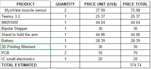
The estimated budget is presented below. We have omitted Ground Shipping and taxes because we are waiting on getting our material approved so we can buy them. For now, it would be wise to round up our number and we agreed on a margin of $100 in case of an accident and also in case we have to pay for 3D printing. This is how we came up with the budget of no more than $500 for the Robotic Arm project.


estimated-budget_1st-iteraation

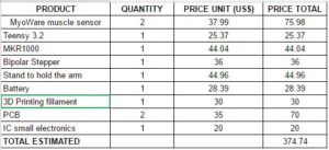
Table 1 – Estimated Budget (First Iteration)

ELECTRONICS AND CONTROL SYSTEM (by Fabian Suske, Electronics and Control Engineer )

BASIC CONCEPT

A brief brainstorming about the prosthetic arm came to the conclusion that biomedical signals (bio signals) shall be used to control the arm. The two kinds of bio signals are EMG (Electromyography) and EEG (Electroencephalogram). The following research showed that both methods would be possible to implement. There are projects available which utilize each signals. But the hassle to get good EEG signals is much bigger then to get good EMG Signals.

Another aspect that came up in the brainstorming was the high precision needed to reach the target of feeding the soldier. Since servos were restricted to use. The focus led to stepper motors. Stepper motors are due to their mechanical construction very precise.

This ideas led to the following basic concept (figure 3):

figure3

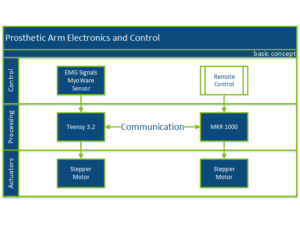
Figure 3 – Basic Concept (Electronics)

EMG Signals are acquired by the MyoWare Sensor Shield. The signals are then send to the Teensy 3.2 MCU. There the signals are processed. The Teensy drives then the designated stepper motors. The motor for the “lifting” action is located above the elbow and is directly connected to the Teensy. The second motor used for radial movement is located below the elbow and is driven by the MKR 1000 MCU. This MCU has Wifi Capability onboard. This allows the system to be remote controlled (as a plan B). The MKR 1000 is also in charge of the power distribution (not included in this graphic). The two MCUs will communicate between each other.

References:

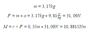
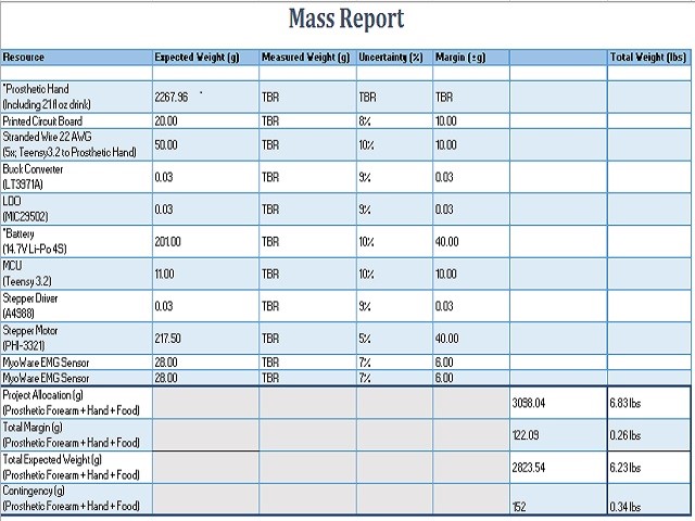
The project requirements state that a Quarter Pounder with Cheese meal shall be consumed. Based on this information we can measure the weight that has to be lifted.

Burger: 196 g.

Soda: 1.369 lbs.

Fries: 142 g.

The heaviest item is the soda with 1.369 lbs. The Hand subsystem stated that their subsystem shall not be heavier than 3 lbs. The weight of the arm itself shall not exceed ¾ lbs. With an allocated weight of 1 lbs. to the electronics the part of the system is around 6lbs. Since estimations were made a margin of 1 lbs is added. So the total adds up to 7lbs (3,17kg).

With an estimated length of the arm of 35cm (14 in) the motor has to deliver a torque of more then 10,8815 N

figure-3-1-therefore-a-motor

Therefore a motor with at least 10,888Nm is required.

Most stepper motors (in our budget) output a torque of 1.5-3NM. So a gear must be used to achieve the needed torque.

Since stepper motors operate at 12V and the MCUs run at less than 5Vs it is not possible to operate them directly of the MCU. Hence a stepper motor driver (stepper driver) must be used.

The stepper driver should be a Surface Mounted Device (SMD, SMT (Technology)). Also the motor should be controlled used with Step and Direction. This type is easy and simple and is sufficient. Therefore the Allegro A4988 stepper driver has been chosen. This driver operates on 3-5.5V and drives motors at 12 VTo limit the thermal output the driver will be operated at under 1 A Load Current.

Therefore the Phidget PHI-3321 stepper motor has been chosen. It operates at 12V and draws a maximum current of 670 mA

figure4

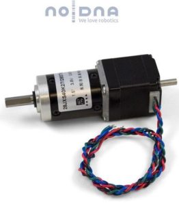
Figure 4 – Stepper Motor for the Elbow

The smaller motor used to rotate the wrist or elbow must still be TBD, but should require less current than the PHI 3321 since less torque is required.

Reference:

POWERTRAIN:

Since the Upper-limb Prosthetic System should work together as a system a common powertrain will be used. Since the space in the hand is limited the powertrain will be implemented in the prosthetic arm.

Based on the given requirements the powertrain can be dimensioned. The Hand needs up to 2.5A on 12V as well as up to 1A on 5V The MCUs operate at 3.3V but can be powered with 5V.

So the prosthetic System needs two Voltage Levels to power the System.

On the 12V level 700mA (peak) each for the steppers and 2.5A (peak) for the Hand sum to a total of 3,9A. On the 5V side the Hand requires 1A and the MCUs in the Arm need an estimated current of 200mA.

To provide 5V without a second power source a 12-5V buck converter will be used. This will add around 500mA to the 12V rail. So the 12V rail must provide 4,4A (peak).

Given this specification the Microchip MIC29502 LDO Voltage regulator has been chosen. This LDO has an enable pin so the 12V can be completely shut off. This provides some interesting efficiency features.

The fact that this LDO can be sampled for free is a plus.

To provide 5V 1A a buck converter will be used due to high efficiency compared to a LDO or fixed Voltage regulator. This also minimizes the head that will be dissipated.

The Linear Technologies LT3971A Buck Converter provides 1.3A continuous Current (up to 2A peak)

This Chip could also be sampled for free.

To power the 12V LDO 14,7V Li-Po Batteries will be used. Li-Pos are wildly available since they’re common in the RC market. 14.7V is the next higher available Voltage above 12V. A higher voltage is required by the LDO.

The size of the batteries has to be more than 1500mAh since the prosthetic system will drain around 4.5A and the time has to be 20 mins minimum. The size of the battery is TBD by the weight and volume that can be allocated to it.

References:

 SENSOR:

The MyoWare EMG has been chosen to rapid prototype because it’s widely used.

The sensor operates between 2.9 and 5,7V and connects to an analog pin on the MCU. The input voltage will be outputted to the analog pin so if you supply it with 5V and connect it to an MCU that operates at 3.3V it will cause damage to it.

To achieve better results in distinguishing the different movements two or more sensors will be used.

figure5

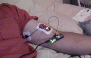
Figure 5 – MyoWare Test with Arduino MKR1000


References:-

system-block-diagram

Figure 6 – System Block Diagram

Given this components the complete System Block diagram is shown in “Figure 3 System Block Diagram”.

The two MCUs are used to reduce the cable tree between the upper arm and the forearm. Since only Power and the I2C Interface must run between (instead of individual cables for the Sensors and Motors).

The Teensy MCU will be located in the upper arm since it is the smaller board. (In the upper arm is less space available.

The MKR 1000 with the Wi-Fi capability will be located in the forearm.

The I2C Interface will connect the two MCUs to allow communication.

References:

MECHANICAL DESIGN (by Forrest Pino, Manufacturing Engineer)

The prosthetic arm project will stem from multiple design ideas and will incorporate the key components that will make this project a success. The prosthetic arm project will utilize modified .stl files from the open source robotics project, InMoov, in order to satisfy the requirements. The provided forearm files will be edited in order to accommodate the robotic hand that will be attached to the prosthetic arm. The .stl files for the forearm will experience most of the modification and will mostly be a guide for the prosthetic arm. Fig. 7 was provided by the InMoov project site and shows the out layering of the forearm. The forearm coverings may be removed completely or modified in a way that shows the internal structure of the arm.

figure7

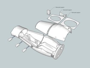
Figure 7 – Basic Design for the Prosthetic Arm

figure8

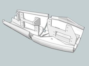
Figure 8 – Inside the Forearm Structure

figure9

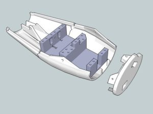
Figure 9 – Forearm and Elbow Assembly


Fig. 8 and Fig. 9 are internal housing designs provide by the InMoov open source project. The InMoov project made use of servos in the forearm while the prosthetic arm group will not be doing the same. The component housing structure for the InMoov design will most likely be removed.
The robotic hand project will not be utilizing the hand designs from the InMoov so integration between the two will be a custom design. The length of our forearm will also be determined by the specifications of the robotic hand. In order to counteract the weight of the arm, the forearm will be shortened as to not overload the DC motor with excessive leverage. One method of reducing weight will be editing .stl files so that less surface area will be printed and structural integrity will remain intact.

figure10

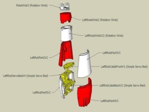
Figure 10 – InMoov design for Forearm

The InMoov site provided Fig. 10. The image shows and labels each part that was utilized in the InMoov design for the forearm. Since the forearm length may be reduced greatly, the only components that may be utilized will be the ones closest to the elbow. The Prosthetic Hand project will be in charge of creating the wrist so the components associated with the wrist in the InMoov design will be removed.

The methods of power and control for the prosthetic arm will differ greatly from the InMoov project. The degree of alteration means that the housing of the internal components will need to be custom. Depending on the size of the forearm, most of the components may need to be housed in the bicep of the prosthetic arm. The mechanism in the bicep that relates to extensions and contractions may not be suitable for our design and can be supplemented for system that utilizes a pulley. Utilizing a pulley could produce less friction than the InMoov design and would provide space for the PCB and other components. If a pulley were to be used, a mounting bracket would be needed for the motor. During research, an .stl file was acquired that would provide insight as to how mounting of the motor would be applied to the bicep.

Since an amputee will not be able to assist, a stand will be developed for testing and demoing. The current design will utilize PVC pipe and a hinge mechanism that will simulate shoulder movements. The stand will allow the prosthetic arm to hang in an orientation that would be similar to an amputee with a prosthetic arm. For demoing purposes, a member of the group will be able to guide the shoulder movements of the prosthetic arm while the other members demonstrate the effectiveness of the artificial limb.

figure11

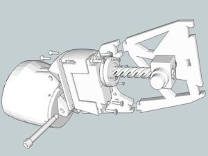
Figure 11- Interconnection of the forearm and bicep

Figure 11 displays the interconnection of the forearm and bicep. The servos used in the InMoov design exceed the capabilities of the DC motor that will be utilized. This may lead to an alternate design that would provide movement to the forearm through a pulley system.

Refences:

SPECIAL ASSIGNMENTS AND DUE DATES: (by Hector Martinez, Manufacturing Engineer)

Design and Unique Task

  • Meet with Prosthetic Hand to ensure proper mating of hand and arm(9/20/16)
  • Analyze InMoov prosthetic arm design and look to modify and simplify for our mission objective (9/21/16-9/28/16)
    • i.e. no need to house strings and motors in forearm based on preliminary Prosthetic Hand design(Instructables: TACT Low-cost, Advanced Prosthetic Hand).
    • Modify InMoov heavy duty bicep design to fit our mission efficiently.
  • Look into design modifications to lighten system weight (9/21/16 – 9/28/16)
    • Trade-off study in materials (weight vs cost)
    • Search for design techniques to reduce weight. i.e. cutting a pattern into the shell
  • Study, analyze, and take apart existing prosthetic arm in ET-111 Lab (9/21/16-9/28/16)
  • Look into cost effective design for a stand to hold prosthetic arm, as well as provide limited movement. (9/21/16-9/28/16)
  • Study gearing, gear ratios, and gear options (9/21/16-9/28/16)
    • Trade-off study between off the shelf gears and 3D printed


NOTE:

Our 2×2 picture was taken from:

http://inhabitat.com/inmoov-is-an-open-source-3d-printed-humanoid-robot/inmoov-3d-printed-printer-robot-open-source-gael-langevin-face/

Since our project structure is going to be based on the InMoov arm.