
S17 Prosthetic Arm: Gear Test
This posts serves as a test of the gears that are going to be used wit the servo to rotate the wrist of the prosthetic arm that also rotates the prosthetic hand.
This posts serves as a test of the gears that are going to be used wit the servo to rotate the wrist of the prosthetic arm that also rotates the prosthetic hand.
By: Moses Holley (Electronics and Control)
Table of Contents
The objective of this test was to gain an understanding of how RPM encoders work along with the Arduino code to manipulate them. We need the shaft encoders to detect wheel slippage and control the differential turning for the Mini Pathfinder.
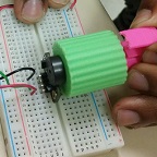
The RPM encoder test was first implemented using the OSEPP Motor Encoder. In this test, We gained an understanding of how the two A3144 hall effect sensors on the chip detect the rotating magnets. Then with the Arduino code converts the rotations in to RPMs. This test was used to measure the speed at which the wheels will turn at the 3dot output voltage of 5 volts. The n20 motors are rated at 6v at a speed of 32 rpm. We used an Arduino Uno because the 3Dot was having trouble uploading at the time.
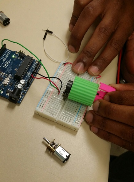
Figure 1. Test Setup
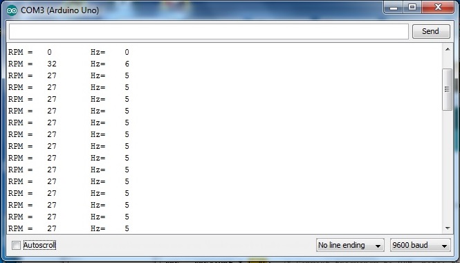
Figure 2. RPM output
Average RPM reading Code: This code waits for 10 readings then gets the avg of the RPMs.
// read RPM and calculate average every then readings.
// This code was retrieved online and we manipulated the reading[index] to get the correct readings.
const int numreadings = 10;
int readings[numreadings];
unsigned long average = 0;
int index = 0;
unsigned long total;
volatile int rpmcount = 0;//see http://arduino.cc/en/Reference/Volatile
unsigned long rpm = 0;
unsigned long lastmillis = 0;
void setup(){
Serial.begin(9600);
attachInterrupt(0, rpm_fan, FALLING);
}
void loop(){
if (millis() – lastmillis >= 1000){ /*Uptade every one second, this will be equal to reading frecuency (Hz).*/
detachInterrupt(0); //Disable interrupt when calculating
total = 0;
readings[index] = rpmcount * 5.45; /* Convert frecuency to RPM, note: this works for one interruption per full rotation. For two interrups per full rotation use rpmcount * 30.*/
for (int x=0; x<=9; x++){
total = total + readings[x];
}
average = total / numreadings;
rpm = average;
rpmcount = 0; // Restart the RPM counter
index++;
if(index >= numreadings){
index=0;
}
if (millis() > 11000){ // wait for RPMs average to get stable
Serial.print(” RPM = “);
Serial.println(rpm);
}
lastmillis = millis(); // Uptade lasmillis
attachInterrupt(0, rpm_fan, FALLING); //enable interrupt
}
}
void rpm_fan(){ /* this code will be executed every time the interrupt 0 (pin2) gets low.*/
rpmcount++;
}
RPM Code: This code gets the RPM of each reading.
// read RPM
// This code was retrieved online and manipulated the RPM.
volatile int rpmcount = 0;//see http://arduino.cc/en/Reference/Volatile
int rpm = 0;
unsigned long lastmillis = 0;
void setup(){
Serial.begin(9600);
attachInterrupt(0, rpm_fan, FALLING);//interrupt cero (0) is on pin two(2).
}
void loop(){
if (millis() – lastmillis == 1000){ /*Uptade every one second, this will be equal to reading frecuency (Hz).*/
detachInterrupt(0); //Disable interrupt when calculating
rpm = rpmcount * 5.45; /* Convert frecuency to RPM, note: this works for one interruption per full rotation. For two interrups per full rotation use rpmcount * 30.*/
Serial.print(“RPM =\t”); //print the word “RPM” and tab.
Serial.print(rpm); // print the rpm value.
Serial.print(“\t Hz=\t”); //print the word “Hz”.
Serial.println(rpmcount); /*print revolutions per second or Hz. And print new line or enter.*/
rpmcount = 0; // Restart the RPM counter
lastmillis = millis(); // Uptade lasmillis
attachInterrupt(0, rpm_fan, FALLING); //enable interrupt
}
}
void rpm_fan(){ /* this code will be executed every time the interrupt 0 (pin2) gets low.*/
rpmcount++;
}
// Elimelec Lopez – April 25th 2013
Although we gained a lot of understanding of how the RPM encoder works we will not use this model for our design. The shape of the OSEPP encoder is catered to a DC motor placed of it to be very close to the rotating magnets. We will have a different design that has the DC motor encased in the wheel which requires that the rotating magnet rotate around the motor. When we decide what kind of encoder will be used there will be an updated blog post.
By: Johnathan Chan (Manufacturing-Chassis)
Intro
Since the Mini Pathfinder has to be able to climb up stairs as large as the wheels, we need to ensure that the bogie suspension has enough of an angle to pivot to overcome the stairs. Measuring the angle of the pivoting bogie will help us determine if it can do this.
Measurements
We were able to measure the degrees of freedom by laying the suspension flat on a piece of paper and making a mark of where it is when it is flat. Then we marked where it is completely up. After we used a protractor to measure the degrees of freedom which is 87 degrees.

Figure 1. Flat on the Ground
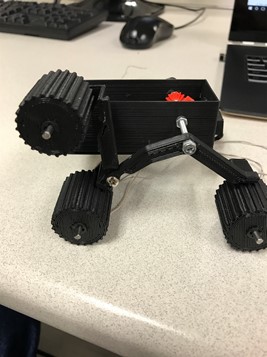
Figure 2. Suspension all the way up
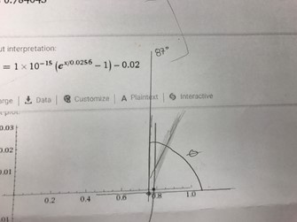
Figure 3. Angle of which the suspension from flat on the ground to all the way up
Conclusion
With the suspension we created, the rover will be able to maneuver through obstacles the size of its wheels.
By: Moses Holley (Electronics and Control)
Introduction
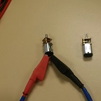
In this test, I will be testing the n20 motors at various voltages. The motors are rated for 6 volts, but the operating boosted voltage on the 3Dot board is 5 volts. The battery is rated at 3.6 volts, should we tap directly into the battery, but is typically fully charged at 4.2 volts [1]. The discharge cutoff voltage is at 2.75 volts, but wanted to test it at a slightly higher output of 3 volts.
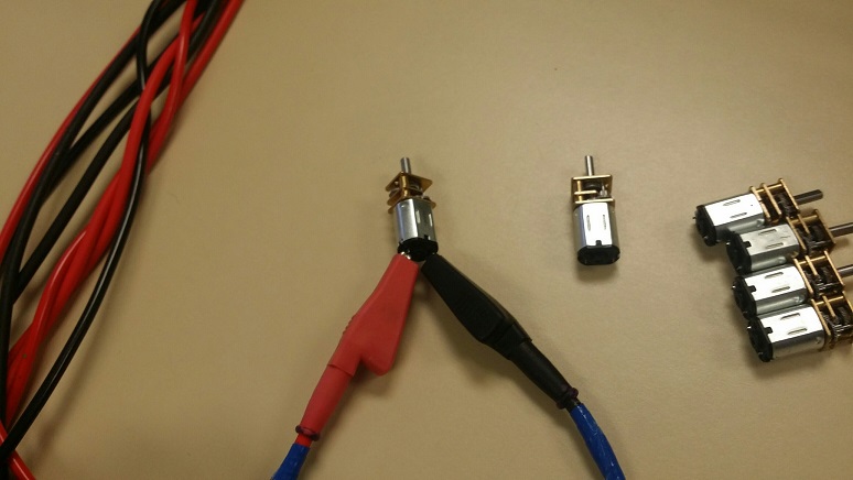
Figure 1. Applying Voltage to the Motor
![]()
Results
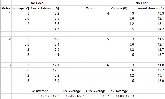
Figure 2. Voltage and Current Results
Conclusion
There is no significant change in the current draw from the different voltages on all the motors. Since the 3Dot motor connectors will use the 5 volts from the boost converter, we will most likely utilize the same voltage output so that all the motors will spin at the same rate. This is an easier solution than programming the onboard motors to spin at the same rate that the other motors.
References
[1] http://www.batteryspace.com/prod-specs/1389-RCR123A36.pdf
Table of Contents
By: Oscar Ramirez (Mission, Systems, & Test)
-Body
Edited and Approved By: Jesus Enriquez (Project Manager)
-Introduction & Conclusion
One of the other challenges that we faced on top of choosing and configuring a color sensor was the challenge of interfacing the Arxterra app custom telemetry with the count dots command. This post covers the strategy and solution we came up with in order to solve this issue.
Requirement L2-1: The Velociraptor shall be able to count the number of dots it encounters in the Custom Maze using an SMD LED to indicate that it counted a dot
Requirement L2-2: The 3DoT shall send custom telemetry to the Arxterra Control Panel via Bluetooth
After configuring our TCS34725 color sensor we needed to implement this into our main code and not just detect the red dots inside the maze, but also count them and find some sort of way to display them. Implementing the red dot detection into the main code was not an issue but displaying the number of counted dots proved to be more of a challenge. A seven-segment display would not be ideal since it would require numerous digital pins on our Arduino and we would also need two seven segment displays to count a practical amount of dots. A much simpler solution would be first counting the dots and display the counted dots by blinking an LED equal to the number of dots counted. For example if we were to collect 14 dots the LED would blink 14 times. To enable this dot count, I created a custom Boolean command that once switched to “ON” would blink the LED the same number of times that are equal to the total dots. Creating a counting dot subroutine and inserting this logic was simple. First I copied the dot counter into a dummy variable so that the value of the counter would remain unmodified. Taking this dummy variable that has the total number of dots that we want to count, I inserted it into a while loop that begins by decrementing it by one and then flashing the LED once. This process repeats until the value of the dummy variable is equal to zero and the LED has flashed the same number of times equal to the total dots counted.

Figure 1: Our custom command that toggles the current red dot count
void countDotsHandler (uint8_t cmd, uint8_t param[], uint8_t n)
{
d=c; // copying number of dots to dummy variable
if (d>0) // counting the number of dots by derementing d
{
while (d>0)
{
d=d-1; // subtracting each dot one by one and setting LED to HIGH for each dot
digitalWrite(8, HIGH);
delay(250); // 250ms delay between LED flashes
digitalWrite(8, LOW);
delay(250); // repeating loop until all our dots are counted
}
}
}
This test for us worked fairly well off the robot and the only challenging aspect of this that we came across was that we did not test the robot for a static walk performance in order to predict about how long we should allow the LED to stay on as it encounters each dot. For the future, the best recommendation is to focus on getting the robot to walk first and foremost.
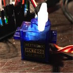
Table of Contents
By: Oscar Ramirez (Mission, Systems, & Test)
-Body
Edited and Approved By: Jesus Enriquez (Project Manager)
-Introduction & Conclusion
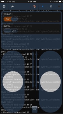
One of the bug requirements that we needed to satisfy for our Velociraptor was giving it the ability to perform a turn in order to navigate the maze. To solve this issue we decided to integrate servos into the robot to turn the hip through the universal joint. This post covers a brief background on the testing we performed through the arxterra app to control the servo for the turn.
Requirement L2-8: The Velociraptor shall be able to turn.
For our velociraptor to turn we needed a servo to control the hip motion to an appropriate angle so that the robot could take a step with the hips turned and take another step with the hips back to their regular state to complete the turn. To control this hip motion a servo motor was the ideal solution.

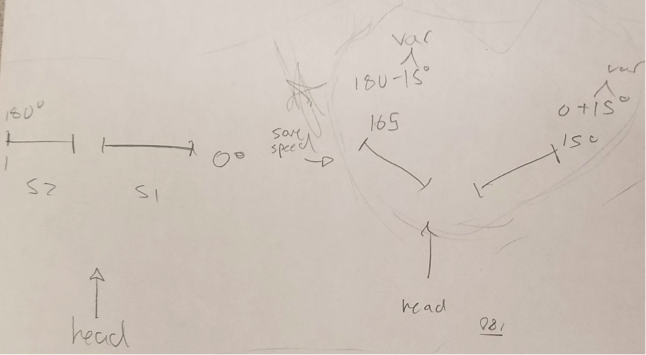
To begin I included the servo library in my code and declared servo11 as my servo. Next I created a handler and subroutine for this servo. A servo motor will typically only rotate from 0 to 180 degrees and for our purpose we would only need it to go from 0 to about 15 degrees to complete the hip motion. Using a Boolean command from the Arxterra app I set two angles, 0 and 15 defining 15 as “ON” and 0 as “OFF”. Finally using the pwn pin 11 on the Arduino I set up the servo and tested the range of motion with the Arxterra app going from 0 to 15 (toggling the on and off switch).
void servoHandler (uint8_t cmd, uint8_t param[], uint8_t n)
{
Serial.write(cmd); // servo command = 0x41
Serial.write(n); // number of param = 1
for (int i=0;i<n;i++) // param = 90 degrees
{
Serial.write (param[i]);
}
int x = param[0]*180/127;
if (x==1){
servo11.write(21);
}
else if (x==0){
servo11.write(0);
}
}
After performing this test, we were able to successfully send commands to the servo to turn a specific amount of degrees as required. The only thing that was the set back in this test was that there was a lot of iterative designing going on throughout the mechanical assembly of the robot so it did not leave us with enough time for full-proof testing. This provided proof of concept for our robot. This is why it is consistently recommended to focus on the mechanics of the robot more than anything before diving into the servo testing for turning.
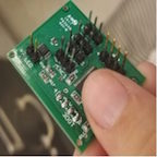
Table of Contents
By: Andrea Lamore (Manufacturing)
Edited & Approved By: Jesus Enriquez (Project Manager)
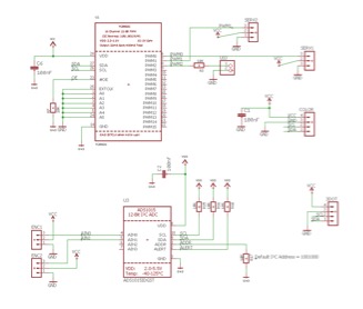
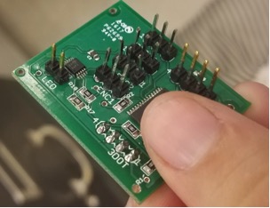
We had to build a custom PCB. Our PCB contained a 12 channel PWM expander the communicated with the peripheral devices that the 3Dot board did not have pinouts to hold. It was important to make sure everything on the PCB was I2C compatible so that the 3Dot board could communicate with it via only 2 pins. Netted to the PWM expander is an LED, potentially 3 servos, a color sensor, 2 rotary encoders, and an A2D converter for the rotary encoders.
Requirement L1-5: The Velociraptor shall use a custom PCB
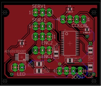
Below is the schematic and the PCB design
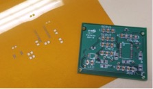
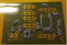
The Board we ordered and the stencil
Surface mount soldering.
Solder pasts is layered over the stencil on to the PCB and then heated in the oven. Before laying out paste the stencil and PCB need to be secured with tape. After the paste is spread flat over the stensil with a credit card the stencil and the tape can be peeled off. The parts I was working with were about the size of a grain of rice, this is a reasonable size if one is hand placing parts. However, one of the capacitors I had to lay over the PCB was the size of a grain of sand, in these instances it makes more sense to use a Pick-and-place. If you do not have access to a pick and place make sure you are aware of the sized components you are ordering.
After the parts are placed over the solder, the board can be placed in the oven until the solder turns a shiny metallic color.
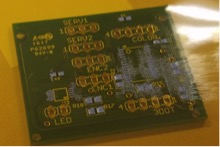
With Unheated Paste and Components
Note that is soldering you PCB with paste is not something to guess at. Soldering the PCB requires a lot of visual observation and attention to detail. You must use your best judgment to ensure that there are no shorts after heating up you board. Most of the teams fail the first time because they treat soldering the PCB more like a step-by-step procedure rather than an art.
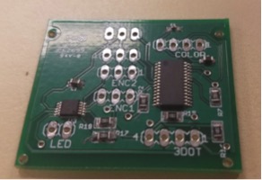
After placing PCB in Toaster oven for a couple minutes
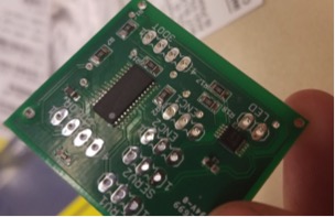
After I attached the through-hole components with a solder iron.
If I could redo the PCB I’d collaborate more with the EnC so that the parts ordered are a reasonable size so that they could be easily hand soldered onto the board. I’d add a more complicated display to the PCB (probably 2 seven segment displays) and more LEDs. I’d use an LED instead of a header. I’d use screw clamps for the power supply instead of a headers- since they hold easier. I’d include some control buttons/switches so I could potentially program various setting for the Velociraptor and change them easily by adjusting the switches on the PCB and resetting the board with a push button.
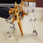
Table of Contents
By: Andrea Lamore (Manufacturing)
Approved By: Jesus Enriquez (Project Manager)
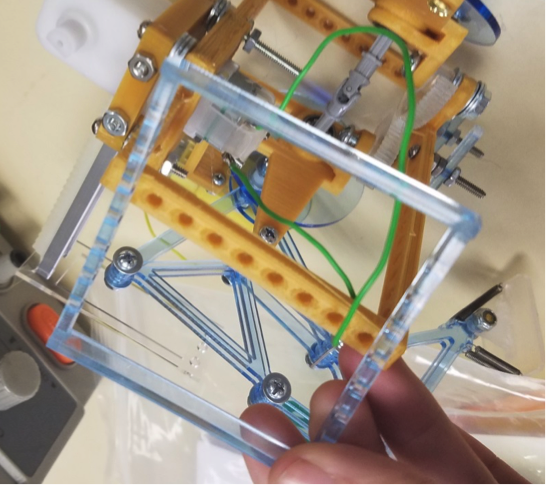
Assembly of the first velociraptor demonstrated some problems that were not clear from the SolidWorks model alone. These problems included a wobbliness/loose motion of the legs, the hip joint was arching when it should have been straight, and the head and tail were bending and lacked stability. In order to increase the stability of the velociraptor I made some changes to the design.
Requirement L1-3: The Robot should resemble the embodiment of a Velociraptor
Assembly of the first velociraptor demonstrated some problems that were not clear from the SolidWorks model alone. These problems included a wobbliness/loose motion of the legs, the hip joint was arching when it should have been straight, and the head and tail were bending and lacked stability. In order to increase the stability of the velociraptor I made some changes to the design.
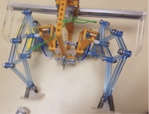
Above, on the first assembly, you can see the head and tail that will now be used only aesthetically. Below is the second Assembly with no electronics attached.
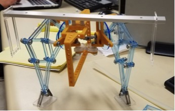
I increased the width of the hip socket so the u-joint wouldn’t bend vertically. Two ball bearing were to be used on each side.
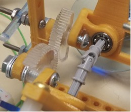
I added stabilizers to the leg so the circle would remain vertical. I also cut the circle large enough to reach the stabilizers without interfering with the shaft motion.
A single servo should be able to move the hips, however 2 servos will be attached and move in sync to increase torque. This requires that they be attached at 90 degrees then move plus and minus 15 degrees respectively depending on whether the legs are turning out or in.
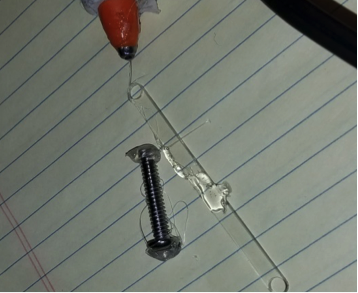
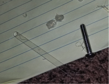
I used thicker acrylic sheeting for the new leg cuts and reduced the size of the shaft holes to the minimum size that could fit a 6-32 screw (which I used for the shaft).
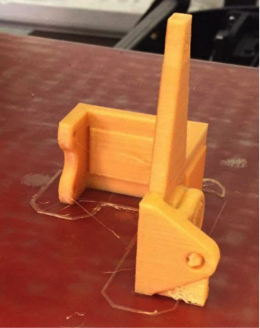
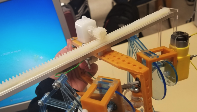
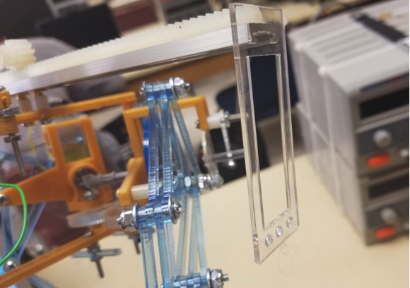
I replaced the head and the tail mechanism with a rack and pinion on a linear bearing. This mechanism requires a DC motor instead of two servos. The DC motors will send feedback from the rotary encoders to indicate how many turns and at what angle the rack positioned at. The DC motor moves the shaft back and forth to adjust the Velociraptors center of gravity. At the end of the shafts are counter weight holders that hang low to the ground to lower the center of gravity and increase balance.

I found the foot mechanism to be somewhat successful in maintaining the stability of the velociraptor while it walks, however, the more weight I added to the velociraptor (DC motors, rack and pinion, etc.), the more resistance I required from the springs. Later I plan to double the amount of springs in the feet.
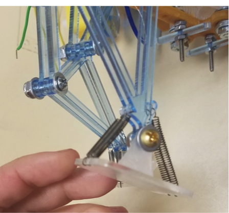
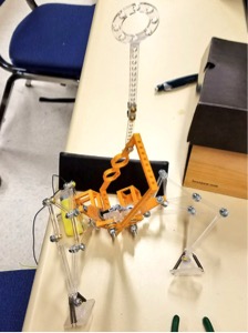
I printed some feet and ordered some rubber. I will eventually glue the rubber to the larger foot platforms and attach them to the raptor. The raptor can stand on rubber far better than it can stand on a smooth surface such as tile or plastic flooring. The velociraptor is shown slipping in the following image. He caught himself by landing on his knee.

Although I decreased the hole size for the 6-32 screw shaft to the minimum there is still some wiggle room in the legs. When You laser cut it actually cuts a little larger than expected (Contrary to 3D printing). If I could cut again I’d reduce the hole size a little more since the legs still have some wobble due to the wiggle room in the shaft holes.
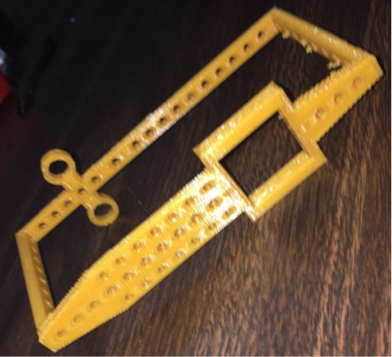
I cut some squares that will eventually be used to mount the 3Dot board and the PCB.
I used hot glue in place of super glue or screws since it is easy to peel off if needed. Hot glue was surprisingly useful for temporary fastening of parts, especially parts that don’t have easy compatibility such as DC motors and Servos. Hot glue caused no damage to these parts after being peeled off. I tested this in the following before and after images.
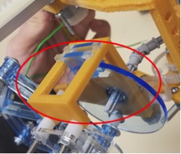
The turning mechanism was successful as can be observed from the following pictures.
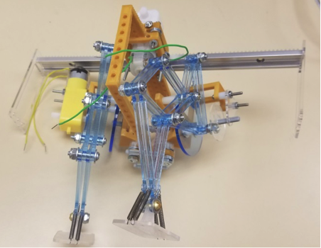
The hips can be turned up to 90 degrees outward on each side. When the legs open the shaft connected to the u-joints and legs slide inward. The more the legs open the more room the shaft needs to be able to slide inward. All of this needed to be taken in to account in order to prevent interference of parts.

The new velociraptor is far less wobbly then the first. The hip mechanism, foot mechanism and the new head and tail mechanism work successful. The only thing I would change is the leg mechanism so that it’s sturdier and less wobbly.

By: Moses Holley (Electronics and Control)
Table of Contents
The objective of this trade off study is to select an electrical device that can detect RPMs for our motors. One way RPM detection is important for our project would be our wheel slip detection.
On the subsystem level, there are many things that we hope to accomplish with rotary encoders. We would like to detect wheel slip, wheel has lost traction or free spinning in the air, for each motor. We would also like to use the rotary encoders within differential turning and the climbing algorithm.
In order to fulfill this requirement, we researched optical shaft encoders, magnetic shaft encoders, and even considered designing a custom shaft encoder PCB.
Pololu’s optical encoders are sensor boards and reflective wheels added to micro metal gear motors with extended back shafts. They have the option of a 3-tooth and a 5-tooth encoder that provides a 12 counts per revolution or 20 counts per revolution. These encoders output are direct photo-transistor outputs. [1]
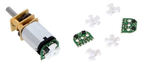
Figure 1. Optical Encoder
Similar to the optical encoder, Pololu’s magnetic encoders are attached to the extended shaft of an geared motor. These boards use 6-pole magnetic discs that can be used to add quadrature encoding. This board senses the rotation of the magnetic disc and provides a resolution of 12 counts per revolution of the motor shaft when counting the ends of both channels. [2]
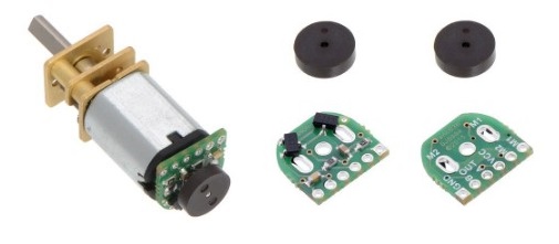
Figure 2. Magnetic Encoder
The custom shaft encoder was inspired by the magnetic shaft encoder just mentioned. The architecture is exactly like the shaft encoder. Although, after detailed research to find the exact EagleCad symbol for our hall effect sensor TLE4946-2K that the magnetic sensor uses. We discovered that the TLE4946-2K hall effect sensor can be with in TO-236-3, SC-59, SOT-23-3 packages. Digikey will send the package in SC-59. Fortunately, there are MOSFETs and Transistors that share similar packages. I choose PNP transistor that has a package of SC-59-BEC, SC59 (SOT23) Motorola, to be place holders for the hall effect sensor that we will purchase.
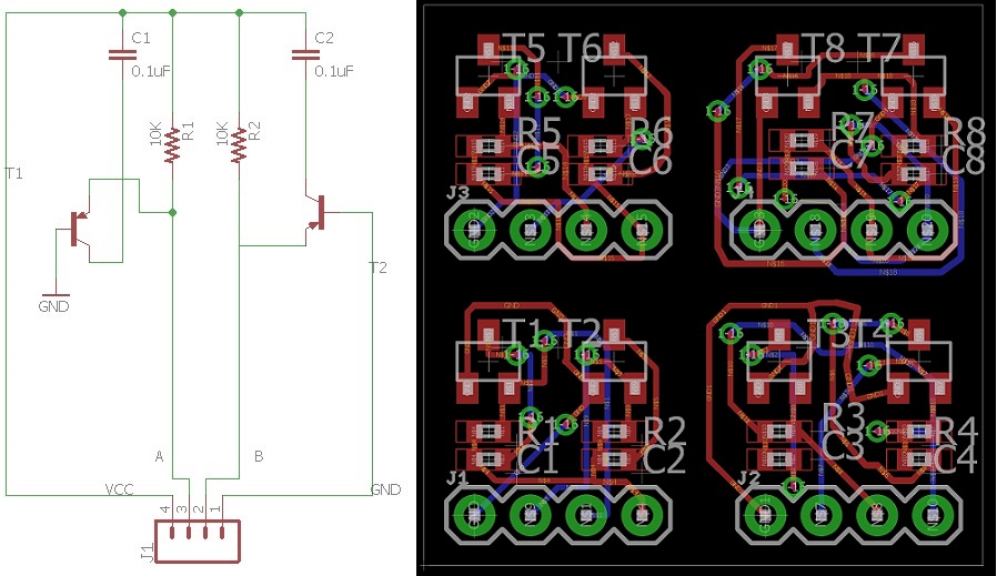
Figure 3. Magnetic Encoder Schematic and Layout
We were considering creating our own because we would have the ability to produce four from one square inch of PCB. The decision factor revolved around cost and time to have them implemented in our design.
In conclusion, we realized too late that we did not purchase the extended metal gear motors that would fit perfectly with the optical or magnetic shaft encoders. We decided to decline creating custom shaft encoders because they would be too time costly and we wanted to ensure that we had working encoders. We chose to purchase the magnetic shaft encoders instead. Although, we did not place the encoder behind the motor but inside a slit that held the motor attached to the suspension. We placed magnets on the inner wheel. As the wheel rotates the sensor should catch the change in poles from the magnet.
[1]https://www.pololu.com/product/2590
[2]https://www.pololu.com/product/3081
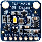
Table of Contents
By: Oscar Ramirez (MST)
-Body
Edited and Approved By: Jesus Enriquez (Project Manager)
-Introduction & Conclusion
One of the requirements for our Velociraptor was giving it the ability to count the number of dots it encounters in the maze. In order to solve this issue, we came up with a creative solution which uses an LED to signal that the Velociraptor has encountered a dot.
Requirement L2-2: The Velociraptor shall be able to count the number of dots it encounters in the custom maze using an SMD LED to indicate that it counted a dot
As part of our mission objective, the velociraptor must be able to detect the colored dots inside the maze that it will also be navigating. The TCS34725 color sensor does a great job of detecting a number of colors, from a long distance (about 4 inches). When the color sensor detects the dot inside the maze a led will illuminate, showing that the velociraptor has stepped over a dot. To begin, the color sensor had four pins that needed to be configured to the Arduino. The SDA and SCL pins were hooked up to analog pins A5 and A4 (SDA & SCL respectively). Then the Vcc and ground pins were connected to 3.3V and common ground inside our test circuit.
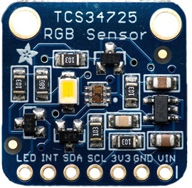
Figure 1: TCS34725 Color Sensor
To program the TCS34725 we first needed the associated library files. Once those were downloaded inside the Arduino library we were ready to begin. I first set the designated LED pin to an output inside the setup. For this experiment I tried only detecting the color red, but also included blue and green in case the color of the dots inside the maze were to change. I created three 16-bit variables to store the data that the sensor picks up and designated them blue, red, and green. Grabbing the data the sensor was currently picking up I stored it inside these variables. These numbers can fluctuate from around 200 all the way up to 4000 per color depending on the intensity and proximity of the color i.e. the closer and clearer the color, the higher the number. While placing the sensor over the color red it does give values of about 3000 but also gives values for blue and green at about 1000. To differentiate between colors I took the average of all of the colors and then divided the particular color by the average. By comparing these values with each other it was easy to differentiate between them. On the code this was done by creating 3 different if statements and comparing the value of each color to each other. If the detected color were red then the LED would illuminate, signaling that red was detected.
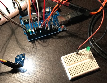
Figure 2: Color sensor facing flat detecting no color (LED OFF)

Figure 3: Color sensor detecting the color red from about 4 inches (LED ON)
Link: Color Sensor Arduino Code
This method for counting dots was the simplest form we could come up with in terms of electronics and coding. One issue that we came across was that we did not take into account how long to keep the LED on after encountering a dot. To solve this issue, it is recommended to work with sending telemetry back through the arxterra app to let the user know when a dot has been counted.