Ultrasonic Sensors – Field of View

By: Jose Alcantar, Electronics and Controls Engineer

HC-SR04 Experiment

Data Sheet Values:

Max Range: 4m

Min range: 2cm

Measuring angle: 15 degrees

Purpose:

Testing the field of view on the HC-SR04 to find a suitable mounting position for the two ultrasonic sensors along the front of the rover.

Procedure:

An object was placed in front of the ultrasonic sensor about 25 inches away; the position of the object was marked and moved in increments of 5 inches until the object was out of view. When the object was no longer detected the position was marked. The angle of the field of view was then calculated.

Results:

Based on the experiment, the angle of the field of view was found to be 18 degrees when measuring an object 25 inches away. The position of the sensors was determined by considering the clearance needed on each side of the rover. When considering the solar panels, the two ultrasonic sensors need to detect obstacles at least 5 inches to each side of the chassis. This will allow the pathfinder to avoid obstacles that may bump into the solar panels.

picture1

Fall 2016 Solar Panels: DC Motor with Encoder Experiment

By Jose Rodriguez (Electronics and Control)

Objective: The following experiments were used to determine if a DC motor can be used in place of a stepper motor by configuring it to be as precise as a stepper motor. Using DC motors will be beneficial to our design as we are trying to provide power.

In the first experiment, the Arduino Uno was connected to an encoder—the signals the encoder provided was then analyzed as the shaft turned.

Parts Used:

  • Motor shield V2.0
  • DC motor with encoder
  • Push button
  • Breadboard
  • 12V Power Supply

400d

Figure 1: Breadboard Configuration

The following code was used:

code1

By taking a look at the serial motor I notice I was receiving zeros and once. The four different patterns received were 00, 01, 10, and 11 (this pattern repeated). Figure 1 explains the output of the serial motor where each output is offset by 90 degrees. The reason we have two outputs from encoder is to determine the direction of the motor.  By analyzing the figure below, we can come up with a true table for direction.

pic1

Figure 1: Output of Serial Motor

If A goes from 0 to 1
B=1 Reverse
B=0 Forward


If A goes from 1 to 0
B=1 Forward
B=0 Reverse

In order to track a pulse each time it occurs, we need to have an interrupt in our code so that we do not miss it. Every time a pulse occurs means that the motor has moved certain degrees. To find the ratio between pulses and degrees, I will measure the number of pulses for 1 rotation using the following code. Without adding power to the motor all that is required is to manually rotate the shaft 360 degrees.

code2

code3

A value of 2071 is what I tested for a full rotation. I divided 2071 by 360 and got 5.75. About 6 pulses will rotate the motor 1 degree and this concept is what I will used to control the motor with precision. If I will I like to move 2 degrees to the left or 2 degrees to the right, then 12 pulses are needed. Once 12 pulses have been received then the motor needs to stop. The next experiment will focus on being able to stop the motor after a full circle.

code4

The following code was used to control the motor. A switch button is used to let the Arduino know when it should rotate. Pressing the button causes the motor to rotates and stops once 2040 pulse have been reach. Due to the fact that the motor is too fast, a perfect rotation cannot be done. A motor with slower rpm but strong torque could potentially respond better. In addition, a gear motor will be more acceptable because we can relate a 360 to 1 gear ratio as 1 degree for every rotation. In the solar panel design, a maximum gear ratio of 50 to 1 is what we can attain. A DC motor could not be used in our project. A stepper motor has been determined as the only option available due to time and gear ratio availability.

Integrated Control Document

Written by: Luis Martinez

Approved by: Carolina Barrera

The purpose of the Integrated Control Document (ICD) between the Prosthetic Arm and Prosthetic Hand systems, as an integrated Upper-Limb Prosthetic System, is to capture essential categories of interaction between both systems upon their unification. This document details explicit responsibilities and agreements between each of the respective groups, and serves as an approved reference document for both project groups to refer to, as a standard for design objectives shared amongst both groups.

Of key regard amongst shared transactions between both groups are those for power, attachment, mass, size, and volume accommodation. Below is a high-level description of these categories:

Power – The Prosthetic Arm will supply power to the Prosthetic Hand via 3x, 22 AWG cables (12V, 5V, GND), allowing up to 3500 mA on 12V, and 1000 mA on 5V from a 1600-mAh, 14.8-V Lithium-Ion Polymer (LiPo) battery stored in the bicep of the Prosthetic Arm system.

Attachment – The Prosthetic Hand will be responsible for allocation of the wrist, of dimensions 76.2 mm x 76.2 mm ± 12.7 mm (3 in x 3 in ± 0.5 in margin). The mounting interface between both systems will be a squared, plated-screw type consisting of 4x, 4-mm screws and a hollow center, allowing the Prosthetic Arm to feed power cables to the Prosthetic Hand in such a way that they are not operationally inhibited by the rotation of the wrist. Furthermore, the Prosthetic Hand will be responsible for any cabling related to storage of their micro-controller (MCU) and printed circuit board (PCB) components within the Prosthetic Arm portion of the integrated system.

Mass – The forearm, hand, and food sustained by the Upper-Limb Prosthetic System should not exceed a combined weight of 6.83 lbs. to correspond with a torque of 10.634 NM at 35 cm for the stepper motor localized at the elbow by the Prosthetic Arm. From this, the Prosthetic Hand will have an allocation of 1.35 ± 0.23 kg (2.97 ± 0.5 lbs.), with an expected weight for the heaviest food item (21 fl oz. drink) at 0.69 kg (1.52 lb.). Overall, the system should be no heavier than 4.0 ± 0.61 kg (8.82 ± 1.35 lbs.).

Size – The Prosthetic Arm, in conjunction with the Prosthetic Hand should be no longer than 35 cm ± 5 cm (13.78 in ± 1.55 in) from elbow to tip of middle finger, from which the Prosthetic Hand will measure 269 ± 13 mm (10.6 in ± 0.51 in) from end of wrist/ forearm attachment to tip of middle finger.

Accommodation (Volume) – As referenced above, the Prosthetic Arm will provide space accommodations for the MCU, PCB units of the Prosthetic Hand, of dimensions 83 mm x 64 mm x 38 mm (3.25 in x 2.5 in x 1.5 in) in effort to alleviate space constraints faced by the Prosthetic Hand.

After the Preliminary Design Review (PDR), suggestions from the customer and class presidents were taken into consideration by both groups, and agreements were reached with respect to the following new categories:

  • Noise: Prosthetic Arm, in conjunction with Prosthetic Hand, will not exceed 60 dB during operation.
  • Safety: Prosthetic Arm will implement an electronic kill switch to disconnect the power supply to the Prosthetic Hand and the Upper-Limb Prosthetic System in the case of a perceived emergency situation or safety concern.
  • Schedule: Prosthetic Arm and Prosthetic Hand groups will have their respective systems ready for integration by an agreed-upon tentative date of Saturday, 11/19/16
  • Aesthetics: Prosthetic Arm, in conjunction with Prosthetic Hand, will have a matching outer appearance, such that in the case of wearing a sleeve and glove respectively, the Upper-Limb Prosthetic System will not attract unwarranted attention.
icd_2

Prosthetic Arm Overview

Moving forward, certain category estimates will be refined, such as the estimated noise threshold to correlate with experimental studies from a McDonalds site visit, and an integrated temperature sensor in the circuitry of the Prosthetic Arm that will be programmed to detect significant deviations from the operating temperature of the Upper-Limb Prosthetic System once integration has been achieved.

Furthermore, an option to vacuu-form, in terms of aesthetics, is being explored by the Prosthetic Arm system in collaboration with the CSULB Design Department pertaining to guidance and permission to use related facilities and equipment. Further changes to this approved document will be submitted for approval, and captured as supplemental revisions.

Fall 2016 Biped – Updated Mass and Power Allocation

By: Brandon Perez (Missions, Systems, and Test Engineer)
Approved by: Ijya Karki (Project Manager)


Table of Contents

PDR Mass Report

pdr-mass

CDR Mass Report

cdr-mass

Changes to Mass Report:

New mass report is more organized and more easily read. Lots of items were bundled into the miscellaneous section. Ultrasonic sensors were taken out. All known masses were inputted and unknown masses were left as “TBD”. Allocation was determined by the mass our servos on the ankles could handle to turn.

PDR Power Report

pdr-power

CDR Power Report

cdr-power

Changes to Power Report:

2 DC Motors are now being used and ultrasonic sensors were ultimately removed off the system. A new battery was selected to be used, therefore we updated our Power Allocation to power that our new battery could provide over the course of an hour. Printed Circuit board was taken off since it practically consumes very minuscule power compared to the rest of the system. All components “Actual Power Consumption” has been left as “TBD” since our system hasn’t been constructed all together yet.

Fall 2016 Biped Requirement Progression

By: Brandon Perez (Missions, Systems, and Test Engineer)
Approved by: Ijya Karki (Project Manager)

Table of Contents

Requirements 1st Draft

September 4th, 2016

Level 1

1.Shall be finished by the 9th of December, 2016 as designed in the CSULB calendar to correspond with the duration of the EE 400D class.
http://web.csulb.edu/~hill/ee400d/F’16%20Syllabus.pdf

2.Shall use a 3Dot board embedded system.
http://web.csulb.edu/~hill/ee400d/F’16%20Project%20Objectives%20and%20Mission%20Profile.pdf

3.Shall use one custom SMD I2C shield.
http://web.csulb.edu/~hill/ee400d/F’16%20Project%20Objectives%20and%20Mission%20Profile.pdf

4.The BiPed shall participate in an end of semester (December 9th, 2016) game where the BiPed’s goal is to outrun Velociraptor out of the arena with Goliath serving as its “eyes.”
http://web.csulb.edu/~hill/ee400d/F’16%20Project%20Objectives%20and%20Mission%20Profile.pdf

5.The BiPed shall use two DC motors to control walking movement of two legs. The choice of the DC motor will be compatible with the 3DOT board.

6.The BiPed shall walk statically and should demonstrate dynamic walking over flat, inclined, and declined surfaces for the entire duration of the game without falling over.

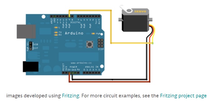
7.“Control of the walking robots will use the Arxterra Android or iPhone application operating in RC mode
http://web.csulb.edu/~hill/ee400d/F’16%20Project%20Objectives%20and%20Mission%20Profile.pdf

8.The BiPed should be able to turn left and right at a maximum of 90 degrees at a time.

9.The BiPed should be able to maneuver around the arena and should avoid collisions with surrounding objects.

Level 2

1.Should use four ultrasonic sensors to support the BiPed in preventing numerous collisions into surrounding objects. Refer to requirement 9, level

2.BiPed will have a Bluetooth v 4 .0 BLE Transceiver integrated circuit that will be able to communicate with the class website of Arxterra. Refer to requirement 7, level 1

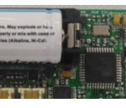
3.The 3Dot board shall be powered by a single CR123A 3.7V 650mA rechargeable Li-ion battery. A 9V battery will be used to amplify the 3Dot board’s signals. Refer to requirement 2 and 4, level 1.

4.The motors will receive their required voltage under operating conditions, as specified above, from the CR123A battery and the 9V battery.

5.The BiPed will use 2 DC motor to control its main walking motion. Refer to requirement 5, level 1.

6.The BiPed should use one wheel attached to one motor on each foot to execute the left and right turns. Refers to requirement 8, level

7.The I2C shield will utilize 4-pin connectors as well as a four-pin cable assembly to connect the four ultrasonic sensors via the I2C interface. Refer to requirement 3, level 1.

8.Biped should use a gyroscope as a sensor to determine its position with respect to the ground and shift center of mass in front of it or behind it when walking on inclined or declined surfaces respectively. The MPU-6050 (Gyroscope + accelerometer) should be used since it was implemented by previous BiPed projects and test software is readily available.  Refer to requirement 6, level 1.

Requirements 2nd Draft

Oct. 10, 2016

Level 1 Requirements

1. Will be finished by the 9th of December, 2016 as designed in the CSULB calendar to correspond with the duration of the EE 400D class.
http://web.csulb.edu/~hill/ee400d/F’16%20Syllabus.pdf (Program Requirement)

Comment: Requirement left unchanged because it emphasizes a time-frame for our project.

2. Shall use 3Dot Board embedded system.
http://web.csulb.edu/~hill/ee400d/F’16%20Project%20Objectives%20and%20Mission%20Profile.pdf (Project Requirement)

Comment: Replaced word “one” to “a”. The previous requirement was forced to be quantitative.

3. Shall create a shield for the 3Dot board that utilize the I2C interference
http://web.csulb.edu/~hill/ee400d/F’16%20Project%20Objectives%20and%20Mission%20Profile.pdf (Project Requirement)

Comment: The new requirement is reworded for clarity. 

4. Shall participate in an end of semester game where the Biped’s goal is to avoid contact with the Velociraptor. The Goliath team will be providing real-time video of the arena to the Biped group.
http://web.csulb.edu/~hill/ee400d/F’16%20Project%20Objectives%20and%20Mission%20Profile.pdf (Project Requirement)

Comment: Updated requirement provides a clearer description of the Mission Profile to the reader. Mission Profile needed to be restated in our requirements since it directly affects our overall system design.

5. Shall use a DC motor(s) to control its walking motion. (Project Requirement)

Comment: Removal of unnecessary information in the second sentence. The updated requirement emphasizes that each leg contains its own DC motor.

6. Shall be able to walk on flat, inclined, and declined surfaces of ± 6.5° angle measurement. (Level 2 Requirement)

Comment: Since the arena is described to be an environment with varying surface angles of ± 6.5° this requirement will now be serving as a Level 2 system requirement as a direct result of Level 1, Requirement 4.

7. “Control of the walking robots will use the Arxterra Android or Iphone application operating in RC mode”
http://web.csulb.edu/~hill/ee400d/F’16%20Project%20Objectives%20and%20Mission%20Profile.pdf (Project Requirement)

 Comment: Requirement left unchanged since it is a project requirement from the customer for the teams to utilize the Arxterra Application for telemetry via Bluetooth to the 3Dot board.

8. The BiPed shall be able to turn left and right. (Level 2 Requirement)

Comment: The previous requirement stated a measurement of turning without any evaluation of why it had to be a maximum of 90° turns. This comment will now be utilized as a Level 2 system Requirement as a direct result of Level 1, Requirement 4.

9. This requirement will no longer be used. (Removed Requirement)

Comment: Removal of requirement because it is not a customer expectation or constraint.

10. Shall use a portable energy sources which should be capable of supplying power of a minimum duration of an hour. (Level 2 Requirement)

Comment: This requirement will be kept as a Level 1 Requirement since it emphasizes how long our system should be able to operate as a requested by the customer.

Level 2 Requirements

1. All sensors and actuators in our system shall be interfaced through the 3Dot board. Level 1, Req. 2

2. The 3Dot board only provides 2 DC motor drivers, and 2 servo drivers for direct component connection, therefore any sensors or additional actuators shall be controlled via an expandable 12C device addresser. Level 1, Req. 3

3. The Biped shall be walk, turn, detect pads on the floor, and operate for a minimum time frame of an hour in order to successfully compete in game designed by the game committee. The Goliath team shall require a proximity range from the Biped to provide video content for the Biped controller. The Arena in which the game will take place shall contain varying surface angles, therefore our Biped shall be able to walk on inclined and declined surfaces of ± 6.5°. Level 1, Req. 4

4. A DC Motor shall be allocated to control each leg to reduce the amount of torque applied if just one motor was being used. Level 1, Req. 5

5. Our Biped’s 3Dot board shall receive telemetry via Bluetooth communication with the Arxterra Application running on a group member’s Android device. Level 1, Req. 7

Requirements 3rd Draft

Oct. 16, 2016

Level 1 Requirements

The Biped Shall Statement:

1.Shall use a 3Dot Board embedded system.

2.Shall have a shield for the 3DOT board that will utilize the I2C interface.

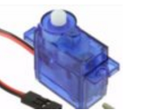
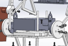
3.Shall use DC motors to control its walking motion.

4.Shall be able to walk on inclines of (+/-) 6.5 degrees.

5.Shall be operated through Arxtrerra firmware via Bluetooth telemetry.  

6.Shall be able to turn left and right.

7.Shall use a portable energy source capable of supplying power for an hour.

Level 2 Requirements

The Biped Shall Statement:

2.The system’s sensors and actuators shall interface through the 3Dot board. All system software shall be compiled onto the 3Dot board.

3.Arxterra firmware files shall be included in our software package for the 3Dot board.

4.An I2C interface shall be used to address additional devices for our system.

5.Two DC motors shall be used on our Biped to produce a walking motion.

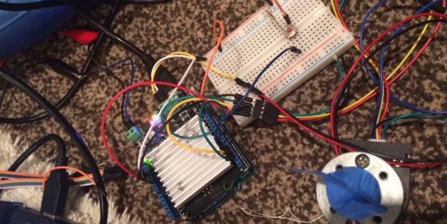
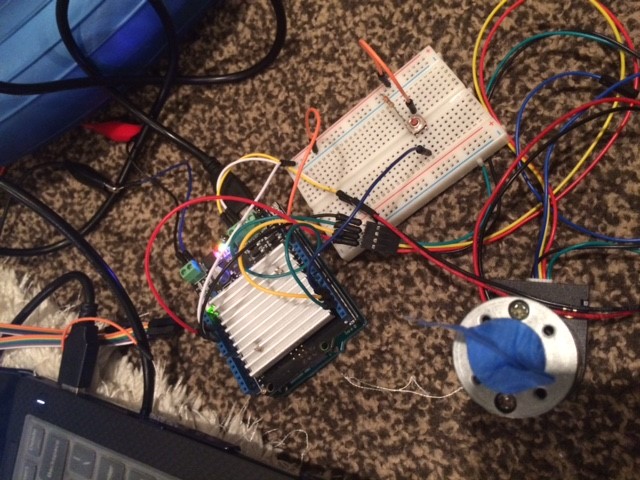
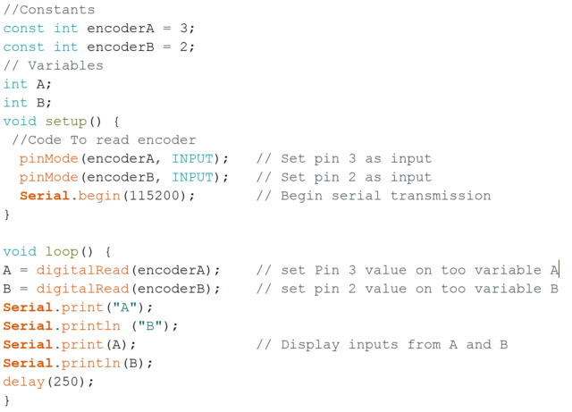
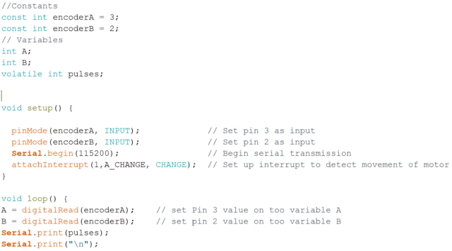
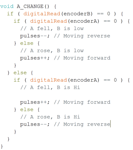
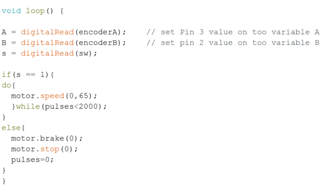
6.Shall use a shaft encoding system to help keep the leg movement system in sync with the weight shifting system.

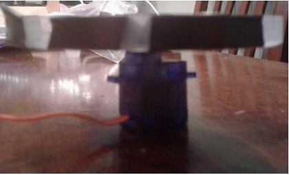
7.Servos on each of the Biped’s feet shall be implemented to produce turning.

8.Shall use a color sensor to detect floor pads in the playing arena.

9.Shall use a RGB LED to display the color of the pad that the color sensor has detected.

10.Shall use a servo to shift the system’s center of mass over from foot-to-foot.

11.Shall use accelerometer to detect when the Biped is on an incline or decline.

12.Shall use PID control method to keep the system balanced on inclines and declines.

13.Shall use a servo to shift the system’s center of mass when walking on inclined and declined surfaces.

Requirements 4th Draft   


 Nov. 6, 2016

Program Requirements:

1. The Biped shall be ready to participate in the game, “Save The Human”, proposed by the game committee on December 14th, 2016.

2. The Biped budget determined by the customer shall not exceed $125.00.

Project Level 1 Requirements

The Biped Shall Statement:

1. Shall use a 3Dot Board embedded system.

2. Shall have a shield for the 3DOT board that will utilize the I2C interface.

3. Shall use one DC motor to control its walking motion.

4. Shall be able to walk on inclines of (+/-) 6.5 degrees.

5. Shall be operated through the Arxtrerra control panel via Bluetooth commands.

6. Shall be able to turn left and right when commanded.

7. Shall use a portable energy source capable of supplying power for an hour.


8. Shall be able to detect power-up zones that will be present during the game.

Project Level 2 Requirements

The Biped Shall Statement:

1. The Biped’s DC Motors and Servos shall have an operating voltage between 4.0 – 6.0V.

2. The Arxterra control panel shall be able send commands to the 3Dot and receive telemetry of the 3Dot board.

3. All external devices shall need to be 12C compatible or included onto an I2C GPIO expander.

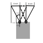
4. Our choice of motor shall have a shaft output to both legs which shall be out-of-phase by 180°.

5. A rotary encoder shall be embedded onto the DC Motor shaft to provide data regarding the shaft’s position.

6. The servos acting as ankles on the Biped’s feet shall be able to turn the entire Biped’s mass of (TBD) while the Biped is standing on one foot. 7. Shall use a color sensor to detect color pads in the playing arena.

8. Shall use a RGB LED to display the color of the pad that the color sensor has detected.

9. Shall use a servo that produce a torque rating of at least (TBD) to raise the robot’s arms laterally.

10. Shall use accelerometer to measure the angle of incline the system is in when standing normal to the surface.

11. Shall use PID control method to keep the system balanced on inclines and declines.

12. Shall use a servo to correct the center of mass of the system when walking on inclined or declined surfaces.


Fall 2016 Biped Experiment/Trade off Study- Encoder

Table of Contents

Encoder Specification

By: Alan Valles (Electronics and Control Engineer)
Approved by: Ijya Karki (Project Manager)

Introduction

A rotary encoder must be used to get the positional reading of the motor shaft. This information is key in understanding which part of the walk cycle the robot is in. For example, if the robot’s right foot is on a color pad, the rotary encoder would read that it is in this position.

Study

With this information, the code could be utilized to read the color pad at this part in the flow chart. Another example is if we want to turn left, the walk function would be called until the left foot is planted. It is at this point that the robot would hold position, shift weight to the planted foot, and then use the ankle servos to turn.

Since a precise stepper motor will not be used in walking, a motor encoder must be used in order to have positional awareness of the robot. The two types of encoders that will be considered are an optical encoder and a rotary position sensor. The optical encoder subsystem uses a QRD1114 phototransistor and diode to send an IR signal and read with the phototransistor. It reads the amount of the IR signal that is reflected. The phototransistor receives an analog signal based on the light that is reflected and absorbed by the phototransistor.  Thus, as the resolution of slices increases as shown in figure 4-17 or the parallax student manual, the resolution is improved. Another circuit is also necessary to convert the analog to a digital signal to be read by an input; the I2C bus is used. The other option is to utilize a rotary position sensor. This is essentially a potentiometer that is connected to the shaft so it is allowed to freely rotate. Its resistance is anywhere between 0 and 10k depending on the angle between o and 360 degrees. However, the Bourns 3322 series position sensor has a unknown region where its value is between 330 and 360 degrees based on the data sheet.

Table 1

Encoder MFG Challenge Additional components Price:
Rotary Bourns Unknown region between 330 and 360 degrees ADS1015 2.73
Optical TI Signal processing and acquisition OpAmp COmparator 1.77

encoder1

In Order to meet scheduling requirements, the rotary position sensor will be used in order to meet our deadline. It will also be used by the velociraptor group which will aid in debugging and coding. The best way to move the all projects forward across The Robot Company is to work in a collaborative environment which is easier if the platform is consistent across all BiPed robots.

An experiment was also done by the Electronics and control Division to test the optical encoder circuits which is similar to a lab done on campus for control systems.

The code below was done by Electronics and Control and is modified from sparkfun guide below.

The code:

/******************************************************************************
QRD1114_Proximity_Example.ino

Example sketch for SparkFun’s QRD1114 Reflectance Proximity Sensor

 (https://www.sparkfun.com/products/246)

Jim Lindblom @ SparkFun Electronics

May 2, 2016

Connect a QRD1114, 330 resistor and 10k resistor as follows:
QRD1114 Pin ---- Arduino ---- Resistors
    1              A0      10k Pull-up to 5V
    2              GND
    3                      330 Resistor to 5V
    4              GND

As an object comes closer to the QRD1114, the voltage on A0 should go down.

Development environment specifics:

Arduino 1.6.7

******************************************************************************/
int QRD1114_PIN = A0; // Sensor output voltage
int LED = 13;
int x = 0;
int y = 1;
int z = 0;
void setup()
{
 Serial.begin(9600);
 pinMode(QRD1114_PIN, INPUT);
 pinMode(LED,OUTPUT);
}
void loop()
{
 // Read in the ADC and convert it to a voltage:
 int proximityADC = analogRead(QRD1114_PIN);
 if (proximityADC < 630){
   digitalWrite(LED,HIGH);
   z=x;
 }
 else {
   digitalWrite(LED,LOW);
   y=1;
 }
if (y==1){
increment();
}
if (z!=x){
Serial.println(x);
}
// float proximityV = (float)proximityADC * 5.0 / 1023.0;
// Serial.println(proximityV);
// Serial.println(proximityADC);
delay(10);
}
void increment()
{
if (digitalRead(13)==HIGH){
 z = x;
 x = x + 1;
 y=0;
}
else if (digitalRead(13)==LOW){
 x=x;
 y=1;
}
}

encoder2

Figure 1

encoder3

Figure 2

Figure 1 shows the realized circuit and an example of the Pizza slices that could be used for the encoder. Since it is difficult to get precise values from the optical sensor, the code above utilizes flags and a threshold value, which when passed dictates a state flag y. The circuit shown in figure 2 is a example circuit that could be used to output a square wave into an available pin on the GPIO expander, SX1509. However, due to the additional circuit complexity, and software hardware integration complexity, the rotary position sensor will be used since it is the most straight forward.

The Bourns 3382 series in conjunction with an ADS1015 delivers a digital value that is able to be mapped onto an SX1509 empty pin. The ADS1015 takes an additional address space on the I2C bus and appears much more straightforward. The optical sensor had to poll and use a counter to keep track of the number of logic HIGH that appeared. There are issues with timing based on this design among other things. Therefore, the Rotary encoder suite in conjunction with an ADS1015 will be used going forward.

Conclusion

In Conclusion a Rotary positions sensor, Bourns 3382 series will be used in conjunction with an ADS 1015. This subsystem was chosen over an optical encoder due to the simplicity, in hardware and software design.

Resources

[1]https://www.parallax.com/sites/default/files/downloads/122-28176-Process-Control-Text-v1.0.pdf
[2]https://www.sparkfun.com/datasheets/BOT/QRD1114.pdf
[3] https://learn.sparkfun.com/tutorials/qrd1114-optical-detector-hookup-guide
[4]http://www.digikey.com/catalog/en/partgroup/3382-series/7106
[5] http://www.ti.com.cn/cn/lit/ds/symlink/ads1015.pdf
[6] http://www.digikey.com/product-search/en?mpart=3382H-1-103&vendor=118
[7] http://www.digikey.com/product-detail/en/fairchild-semiconductor/QRD1114/QRD1114-ND/187536

Fall 2016 Biped Experiment- Ankle Servo

Servo Ankle

By: Alan Valles (Electronics and Control Engineer)
Approved by: Ijya Karki (Project Manager)

Table of Contents

Introduction

An unique design of Fall 2016 BiPed is the use of ankle servos. An experiment was done in order to see how much mass/weight can be held up on one ankle servos at a time. This is one of the primary constraints when selecting materials because the entire weight of the robot must be turned with the ankle servos.

Study

All Servo motors have a stall torque which is the amount of torque that causes the servo to be fixed or not move.

Torque = Force * Lever arm and Force = mass*acceleration_due_to_gravity.(9.8m/s^2).

However, the ankle servos are slightly different than conventional servos because the entire weight of the robot is not hanging directly on the lever arm, but rather the force of the object due to gravity is parallel to the shaft of the servo. Under Ideal conditions, the Center of Mass would be Entirely over the shaft which would mean there is no torque. However, the test was done to see how much mass could be put directly on top of the servo.

servo-experiment1

Figure 1

A Centech scale with a maximum reading of 500g was used for measure the weights of various objects. Ultimately, a coffee cup was used as the maximum weight of about 450g. However, the movement of the servo with the weight on top was not stable. 450g was the maximum mass achieved before the material was not stable directly on top of the servo. A plastic plate was fixed to the top of the servo in order to load the plate with various materials.

servo-experiment2

Figure 2

servo-experiment3

Figure 3

servo-experiment4

Figure 4

servo-experiment6

servo-experiment5

/* Sweep
 by BARRAGAN <http://barraganstudio.com>
 This example code is in the public domain.

 modified 8 Nov 2013
 by Scott Fitzgerald
 http://www.arduino.cc/en/Tutorial/Sweep
*/

#include <Servo.h>

Servo myservo;  // create servo object to control a servo
// twelve servo objects can be created on most boards

int pos = 0;    // variable to store the servo position

void setup() {
  myservo.attach(9);  // attaches the servo on pin 9 to the servo object
}

void loop() {
  for (pos = 0; pos <= 180; pos += 1) { // goes from 0 degrees to 180 degrees
    // in steps of 1 degree
    myservo.write(pos);              // tell servo to go to position in variable ‘pos’
    delay(15);                       // waits 15ms for the servo to reach the position
  }
  for (pos = 180; pos >= 0; pos -= 1) { // goes from 180 degrees to 0 degrees
    myservo.write(pos);              // tell servo to go to position in variable ‘pos’
    delay(15);                       // waits 15ms for the servo to reach the position
  }
}

The Arduino Servo.h library was used in conjunction with the test code above. However, the default delays were modified in order to slow down the motion for test mass stability. I improved the process by using other smaller masses that are more compact and easier to load and balance onto the test plate. Visual inspection showed that the servo motor performed with no noticeable speed decrease even with nearly 500g on it. This was a surprising result and in the future more in depth study will be done to load it past the maximum scale reading of 500g.

Conclusion

In conclusion, various masses were loaded onto the top of a servo. The maximum mass on affixed on top of the servo was 450g. However, based on visual inspection and more mass can be attached as long as it is stable.

Reference

[1] https://www.arduino.cc/en/Tutorial/Sweep

Fall 2016 Biped Trade Off Study- Ankle Servos

Table of Contents

Ankle Servo Selection

By: Alan Valles (Electronics and Control Engineer)
Approved by: Ijya Karki (Project Manager)

Introduction

The most recent design calls for 4 servos to be utilized. Two servos will function to shift the center of mass onto the planted foot during walking motion. The remaining servos will as the ankle which will allow the robot to turn during walking motion.

Study

Since there are four different servos that have different requirements, the ankle servos will be compared. The other servos are still to be determined so that the necessary torque required to move the CoG to balance while turning is considered.

Servo MFG Voltage Torque(stall) Mass Cost
9g Varies 4.8-6V 18.9 oz-in 9g Free(3.95)
ES08A Emax 4.8-6V 21oz-in 8.5g 4.95
HS-53 Hitec 4.8-6V 16.70z-in 8g 7.19

Under ideal conditions, the CoG will be directly on top of the shaft therefore, torque requirements will be dependent based on the position of CoG and total weight of the robot. Due to these assumption, all of the servos will meet the torque requirements. Therefore, the primary constraint will be cost. This leads BiPed to utilize existing TRC inventory and select the 9g servo. If the servos were to be bought due to stripped gears on existing parts or other issues with inventory, the Emax will be purchased depending on the total budget of the robot due to other subsystems.

Conclusion

In conclusion, the current existing inventory of 9g servos will be used for the ankle servos. This is due to the primary constraint.

Resources

[1]http://www.robotshop.com/en/9g-micro-servo-motor-4-8v.html#description

[2]http://www.emaxmodel.com/es08a-ii.html

[3]http://www.robotshop.com/en/hs-53-feather-nylon-gear-servo-motor.html

Fall 2016 Biped Trade Off Study- Motor

Table of Contents

Battery Selection

By: Alan Valles (Electronics and Control Engineer)
Approved by: Ijya Karki (Project Manager)

Introduction

The walking Biped robot requires a dc motor to control its walking motion. A DC motor can vary in specifications such as operating voltage, current, RPM, torque, and size. Therefore, it is necessary to pick a DC motor that will operate within our electronic system. Furthermore, the customer requested that the walking motion be produced using DC motors.

Study

Most hobby or toy DC motors operate at a high RPM in the hundreds or even thousands of revolutions per minute. Our current mechanical design has us use a Tamiya gear box in order to step the RPM done and to increase the torque ratio. The Tamiya gearboxes are usually recommended for this since they are flexible in the gear ratio available in one single kit.  For example, the Tamiya 70167 Single gearbox (4-speed) Kit has 4 possible gear ratio configurations, 12.7:1,38:1,115:1, and 344:1. Thus, to meet schedule requirements an all in one Tamiya motor and gearbox subsystem is preferred. However, The Robot Company has existing components that are GM-9 which will also be considered.

Table 1 Motor Comparison

Motor Manufacturer Voltage Stall Current NoLoadCurrent RPM Torque Cost
70167 Tamiya 3V 2100mA@3V 150mA@3V 12300 .5 0z-in 7.55w/gearbox
1117 Pololu 6V 800mA@6V 70mA@6V 11500 N/A 1.99
GM9 SolarBotics 3-6V 400mA@3V 50mA@3V 40RPM 44oz-in Free

The will output 5V so actually testing will need to be done. As Table 1 shows, the motor that comes default with the Tamiya gearbox will be much higher than the required stall current. The PTC fuse is rated for 750mA so this is our driving constraint. Pololu 1117 is just above the PTC rated value so it should be sufficient, but more testing must be done to verify. In conclusion, it is recommended that the Tamiya Gear box be used, but the default motor be replaced by the pololu 1117 which is the same form factor. Secondly, a design which utilizes a single GM9 will also be considered. It is important to note that the DCDC converter outputs 5V. Thus, the motor will be driven at 5V. It has been shown that running Tamiya motors higher than spec voltage is adequate at 5V to meet mission profile[4]. However, this will shorten the life cycle of the DC motor and is not recommend but it is an option.

Conclusion

In Conclusion, The Pololu 1117 DC motor with Tamiya Gearbox in the 70167 will be utilized in the BiPed Design. The gearbox will allow for flexible configurations resulting in adjustable torque and rpm outputs. Furthermore, the motor chosen will utilize a 130 hobby motor form factor which is required to integrate with the Tamiya gearbox.

Resources

[1]https://www.pololu.com/product/118
[2]https://www.pololu.com/product/1117/specs
[3]https://www.pololu.com/product/188/specs
[4]https://www.pololu.com/docs/0J11/all#3

Fall 2016 Biped Trade Off Study- Battery

Table of Contents

Battery Selection

By: Alan Valles (Electronics and Control Engineer)
Approved by: Ijya Karki (Project Manager)

Introduction

A Battery must be chosen in order to provide power to the entire system of the Biped. The motors and servos will be the main power sink onboard our system. The rest of the unit will be nominal in comparison to the continuous rotation that will be provided to the motors during normal walking operation.

Study

The default design of the 3Dot board was chosen by the Arxterra team to utilize a 3.7V RCR 123A. However, the team designed the 3Dot board to be flexible and allows for an external battery utilizing a JST connector. In order to meet scheduling requirements, we will assume that the proper discharge rate is used across entire system.

Battery Mfg Voltage Capacity 1hr power Chemistry Mass Cost
RCR123A Varies 3.7V 650mAh 390=>1.4W Li-ion ~50g Free
B0072AEHIC Turnigy 7.4V 1000mAh 600->4.4W LiPo ~23g 9.89
LP-503562 Adafruit 3.7V 1200mAh 720->2.6W LiPo ~23g 9.95
34117 Tenergy 7.4V 2200mAh 1320->9.7W LiPo ~136 14.99

Conclusion

As an estimation, the motors should draw anywhere between 150mA – 300mA at 5V (1.5W)during normal operation. Another estimation is that the cutoff voltage will be reached at .4V capacity. Thus the entire battery capacity cannot be utilized. However, the servos utilized will be have a operating voltage range of 4.8-6V. Although they can be utilized directly at 3.7V if they are connected directly to the battery, the voltage will decrease as the battery voltage lowers over time. Thus, a LDO will be used to regulate the voltage to the servos. Thus, a 7.4V battery will be used in order to raise the voltage delivered to the servos, since the mission profile calls for a worst case of 60 minutes. The battery should be able to supply at a minimum 1.5W continuously. Therefore, the Turnigy B00 will be selected due to its compromise between cost, mass, and capacity. Furthermore, it operates at the necessary voltage. Since it is used for hobby RC cars it also has necessary discharge rates.

Resource

[1]https://www.amazon.com/Turnigy-1000mAh-Lipo-HobbyKing-Battery/dp/B0072AEHIC/ref=sr_1_2?ie=UTF8&qid=1478476586&sr=8-2&keywords=7.4v+lipo

[2] https://www.amazon.com/Olight-Lithium-ion-Rechargeable-Batteries-Flashlights/dp/B01K7I05G8

[3] http://www.robotshop.com/en/lipo-battery-cell—37v-1200mah.html

[4] https://www.amazon.com/Tenergy-2200mAh-Battery-Banana-Connector/dp/B0192AVMGO/ref=sr_1_5?ie=UTF8&qid=1478477368&sr=8-5&keywords=7.4v+lipo&refinements=p_89%3ATenergy

[5] http://web.mit.edu/evt/summary_battery_specifications.pdf

[6] http://www.silabs.com/Support%20Documents/TechnicalDocs/Selecting-the-Optimal-Battery-WP.pdf