Spring 2016 3D SMD: Reel Feeder Bracket
By Nasser Alsharafi (Manufacturing)
Table of Contents
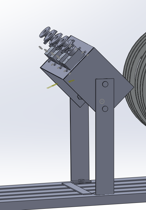
The Reel Feeder
The Reel Feeder shown above is a major component of the pick and place machine. This component is fully automated, and has custom fabricated aluminum parts. It is made up an aluminum base, four SMD part reels, four servos, four legs, and one axle, 4 spacer drums.
The base has four cut channels that are 8mm wide. There are four reels that are positioned on an axle that spins freely. This forces the component tape in the reels to be channeled through the 8mm grooves. There are additional legs that are bolted to the base that hold the axle and the SMD part reels.
The Base
The base is (10.0 inches long x 4.0 inches wide) the base has four channeled grooves spaced by 8mm across. The base has a tape guard that spans the entire width this is to ensure that the tape stays in the grooved channel.
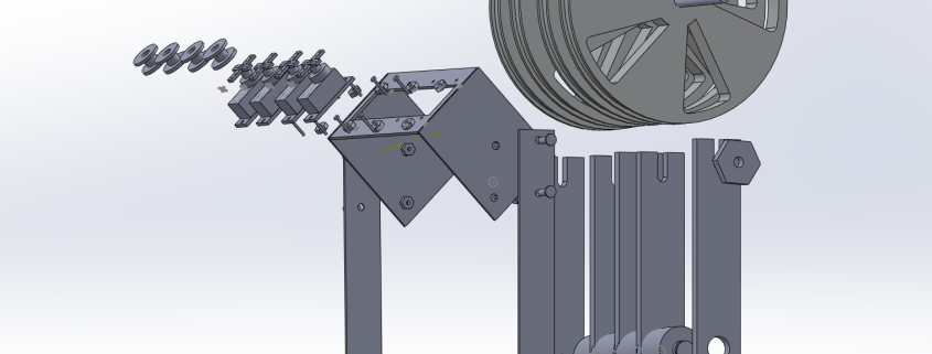
The Reels
The four reels made of plastic that are positioned on an axle that spins freely. The reels spin and dispense the parts onto the aluminum table. The part reels are 5 inches in diameter. Two 5-inch long legs bolt into the base hold up the reels and axle. The reels hold SMD component tape. A plastic cover seals the tape. The size of the components in the SMD tape are very small at 0402.
The Custom Servo Platform
The four servos are mounted onto an adjustable platform by 8 screws. There are four spools attached to the servo, which contain the tape as it wraps up the plastic. The platform is set at 45 degrees from the base. This allows the plastic cover to be pulled off the SMD part tape, and advances the tape simultaneously. The device has legs for the custom bracket that are mounted by 2 screws to the base. The custom servo platform is fabricated from a rectangular piece of aluminum. The servos placed in a 0.9 inch cut out section of the aluminum are evenly spaced out the entire length of the 4.0-inch platform.