Spring 2016 3D SMD: Z-Axis Linear Slide Actuator
By Henry Nguyen (Electronics and Control)
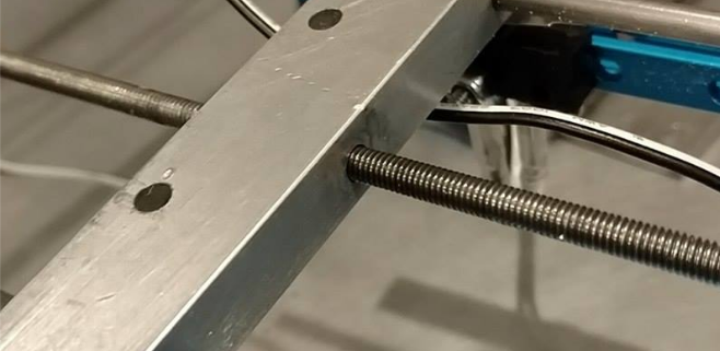
Introduction
For our Z-Axis actuator, we found that our thread drive will constantly cause our nozzle to shift towards the left when going down and towards the right when going up. This was caused by the two 4mm rods and the thread screw we were using. A slight solution was to attach a rubberband to our nozzle to prevent it from shifting. The following Youtube video shows the problem our nozzle has when going up and down:
https://www.youtube.com/watch?v=Rw_LVb8K-G4
We found that in order to prevent this type of error, we had to have a completely new design for our Z-Axis actuator.
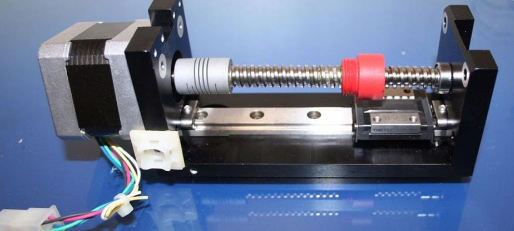
Linear Slide Actuator
We found a cheap linear slide actuator as shown in the title picture on eBay. After purchasing this sliding unit, we found that the slide will be sturdy enough to attach our A-Axis stepper motor as well as keeping the nozzle in a linear fashion. I needed to design a new bracket that will screw into the sliding unit as well as attaching to our red nut on the lead screw.

Figure 1. Linear Slide Bracket Sketch
For my bracket design, I would attach the linear sliding unit to the top of my bracket with the four holes. The red nut will go through the large circle in the middle. The two screws on the bottom will allow us to attach our A-Axis stepper motor bracket. The last screw hole on top of the A-Axis stepper motor bracket will allow us to screw into the red nut. This will keep the red nut in place and allow us to move the hole unit up and down.
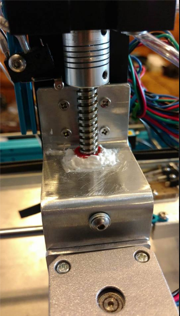
Figure 2. Linear Slide Actuator Bracket
For the bracket, I had to apply some silicone to the red nut in order for it to stay in place. The screw did help to keep it in place; however, I wanted to make sure the red nut is completely stationary.
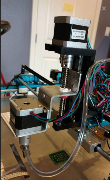
Figure 3. Full View of Linear Slide Actuator
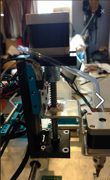
Figure 4. Side View of Linear Slide Actuator
I uploaded a Youtube video showing the linear slide actuator in action.
https://www.youtube.com/watch?v=UqnxF44cEr8
Conclusion
Overall, this linear slide actuator is a success. It completely eliminated all wobbling caused from our old thread drive kit from Makeblock. We are able to go up and down smoothly as shown in the Youtube link above. This will allow us to rerun all of our accuracy tests to ensure that we are as accurate as possible when picking up surface mount components.