By: Dylan Hong (Design and Manufacturing Engineer)
Approved by Kristen Oduca (Project Manager)
Table of Contents
Computer Simulation
3D Model
After creating a preliminary design sketch and determining the dimensions, I created a 3D model of the Goliath using Solidworks as shown in Figure 1 .
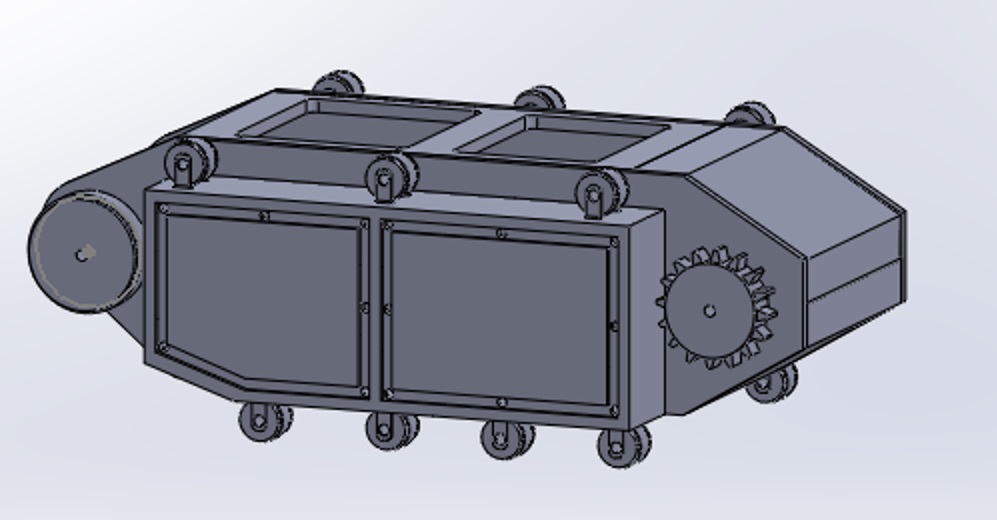
Figure 1 – 3D Model of Goliath Side View
For the body, I created five parts: the side panel, side box panel, and top panel with doors, top panel with hinged doors, and the bottom panel as shown in Figure 2 from a top view angle.
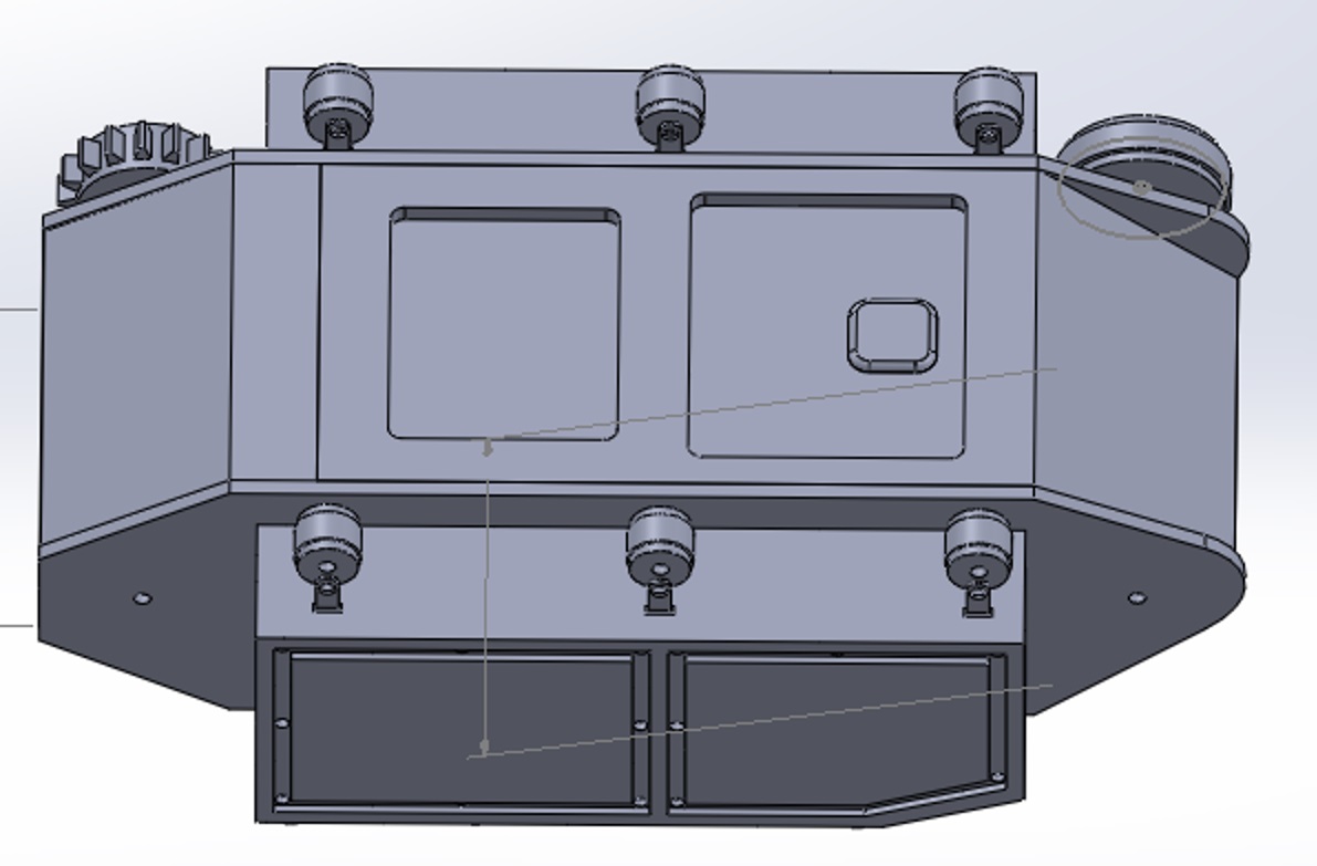
Figure 2 – 3D Model of Goliath Top View
The side panel consist of two holes made for the shafts of the drive and large road wheels. The side box includes seven road wheel holders and will be attached to the side box with screws and bolts. The top panel with doors were created to support the smartphone’s camera and periscope. The top panel with hinged doors will be connected to the top panel with doors and will act as hinged door that will open upwards to insert the smartphone and access the components of the 3DOT board and PCB board.
For the sub components of the body, I modeled the wheels and the smartphone. There were three different wheel types: the drive wheel, the large road wheel, and the small road wheel. The drive wheels are connected to the motors and will be used to rotate the tracks and the other wheels. The large road wheels also moves the tracks but will not be connected to the motors. The small road wheels will be connected to the side box holders and will rotate with the tracks. The smartphone model was created to display the fitting of the phone within the body and its camera’s position in conjunction with the opening doors of the top panel. The camera of the phone must be within the opening of the doors so that the periscope can be placed upon the lens to broadcast our live feed.
3D Print Time
Now that we 3D modeled the Goliath, I was able to work with my division manager to find out the 3D print time of our model with the use of the Makerbot software. We determined the settings of the printer to be at standard quality with a layer height of 0.20mm, 20% infill, raft, and 3 shells shown in Figure 3.
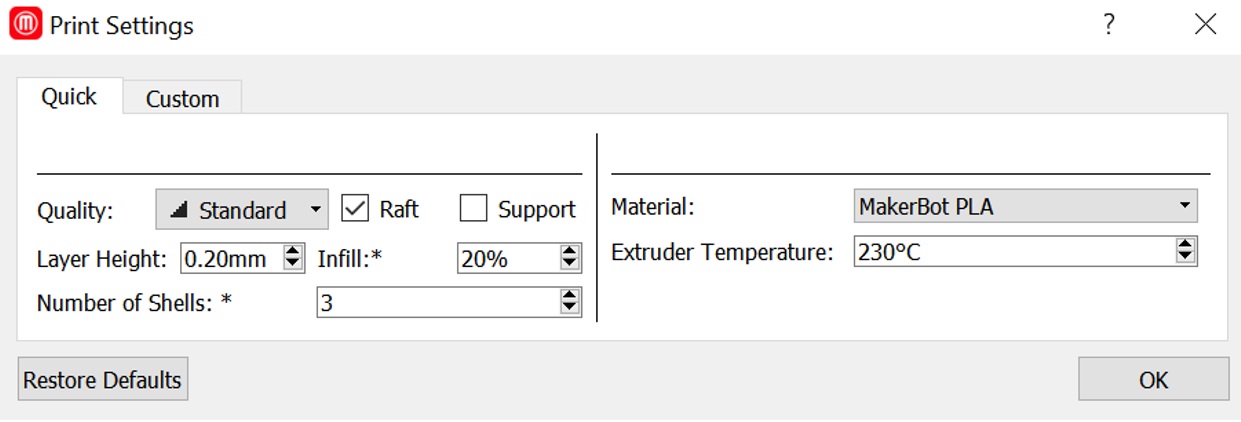
The material we used was PLA with an extruder temperature of 230 degrees Celsius. With these settings, our total print time of the Goliath body was estimated at about 22 hours shown in Figure 4.
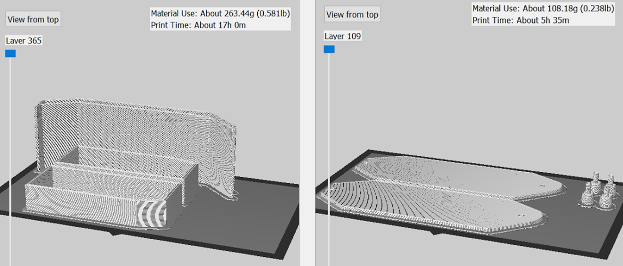
The 22 hour print time exceeded the level one requirement of all components being printed need to be printed in a six hour period.
The Makerbot software also assisted us in finding an error with the side panel and side box of our model, in which Solidworks was unable to detect. The width of the side box dimensions was not long enough and would have brought difficulties when connecting the parts together as shown in Figure 5.
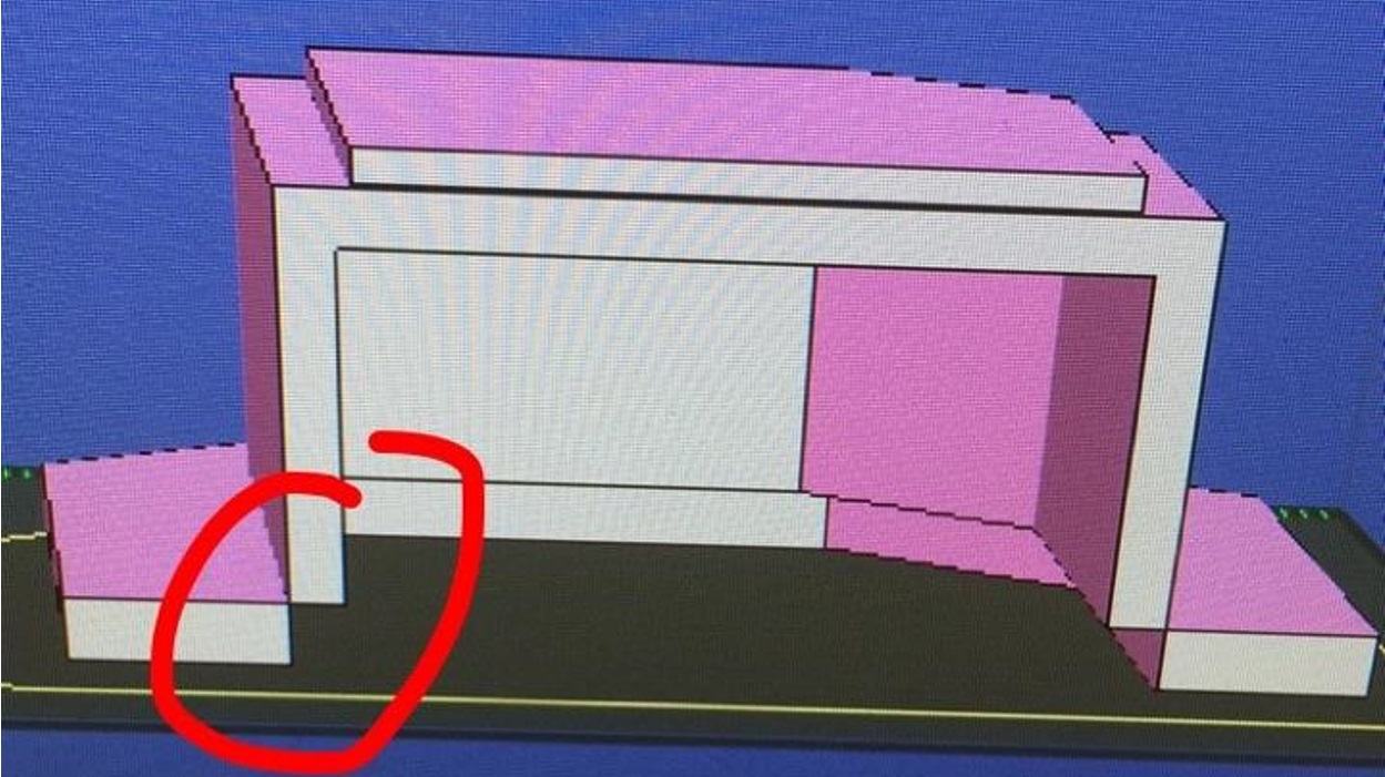
This led to the remodeling of the side box, which resulted in an easy fix of increasing the width of the box by 0.25 inches.
Model
3D Printing
We 3D printed only the side box just to see how it would come out since it was our most difficult part as shown in Figure 6.
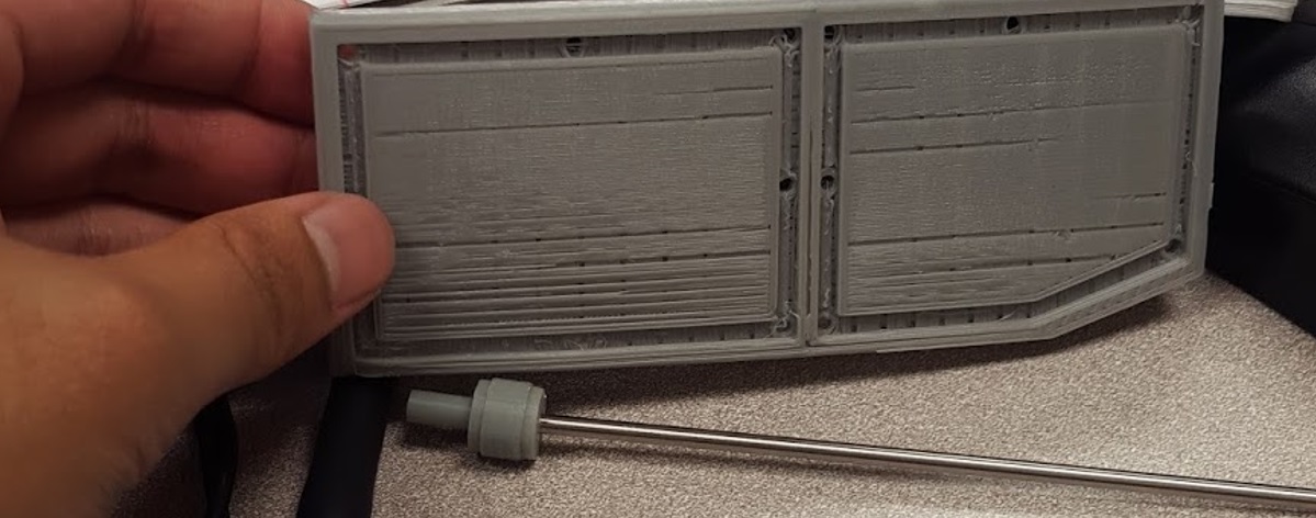
The printed side box was sturdy but lacked details because of the amount of infill used, which was 20%. As infill increases, print time and detail will too.
Conclusion
Overall, our initial design met most of the level one and level two requirements except for the print time requirement with a total of six hours and two hours per part. Also, upon meeting with the customer in regards to our design, he suggested that we make our final product as small as possible, where the components were tightly fitted. This meant that we had to change the scaling of our design and that the smartphone must be removed from the body and replaced onto the top panel of the Goliath.
Introuction
Requirement: The Goliath shall be a scale model of the Goliath 302 tank.
Our ENC has been working with Professor Hill in order to create a more detailed code to find the exact location of the biped. This caused us to change our design to meet certain criteria for the sensors.
Placement of Sensors
For our hardware design, we made some important design changes in regards to the mounting of the sensors, the tracks and the wheels.
For the sensors, our goal was to find the ideal placement without compromising the size of the Goliath. In the images, we considered enclosing the sensors in the front top as shown in Figure 1.

Figure 1 – Sensors in the Front
However, the Goliath looked more like a frog compared to a tank. In order to try to keep the sensors enclosed within the body we made the Goliath bigger, shown in Figure 2.
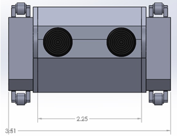
Figure 2 – Bigger Goliath
However, after the customer saw how small our previous Goliath was, he wanted it to keep it around that size. This increased the Goliath’s size dramatically. As our electronics continued working on his code, we also found out that the sensors must be a certain distance apart in order for the code to work. If they are too close, the sensors would act as one sensor as opposed to two. The sensors ideal distance is about 4 to 6 inches apart. I tried to make another model with the sensors on the outside shown in Figure 3.
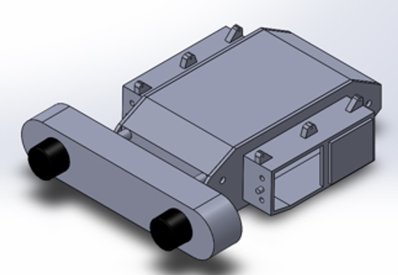
Figure 3 – Sensors on the Outside
However, the sensors took away from the Goliath. Next, we considered an attachment bracket for the sensor that would clip onto the LG G2, but after speaking with the customer he wanted the sensor to be a part of the goliath and suggested it be hinged onto the front top panel. The sensor attached to the phone is shown in Figure 4.

Figure 4 – Sensors as Phone Clips
After constant brainstorming, I realized that placing the sensor onto the front top panel was not going to work because there wasn’t enough space, so I suggested placing it onto the side panel. We used mini brass hinges for the sensor doors and for the opening of the top and bottom panels as shown in Figure 5.
![]()
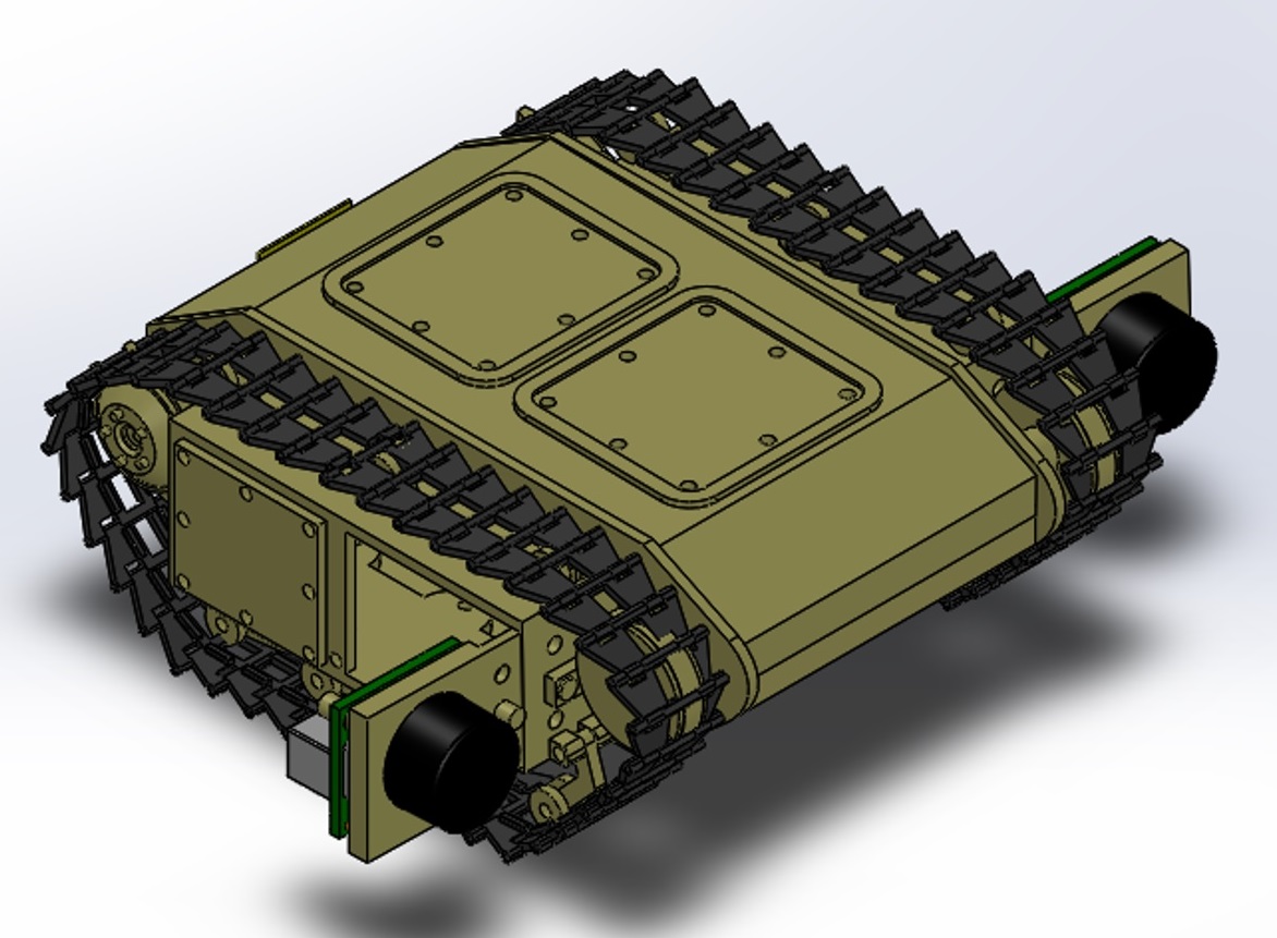
Figure 5 – Sensor Doors
We also changed the top panel now has an “X” support structure to ensure that the Goliath can withstand the forces applied by the LG G2, which can be seen with the static study. We added mounting holes for the bottom panel to connect with the side panels and used 2mm screws to secure its position. We added snap hook features to the top panel to secure the top with the rest of the parts when closed. The front of the side panel and sensor door also has an extruded 3mm circle with a rectangular bar, which is used to hold the sensor door open and keep it from swinging back and forth. The modeled version is shown in Figure 6.
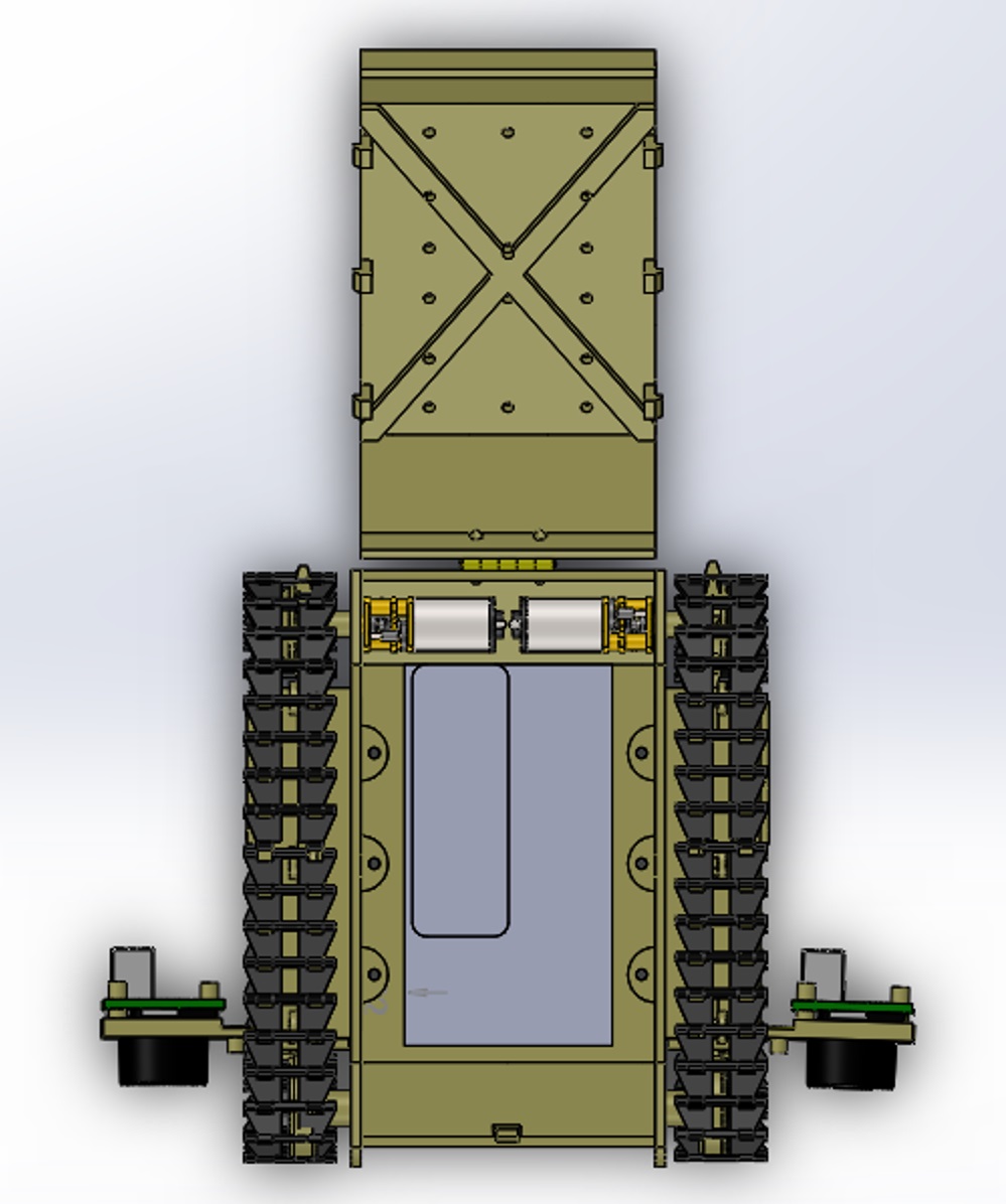
Figure 6 – Modeled Support Structure
The 3D printed version is shown in Figure 7 and 8.
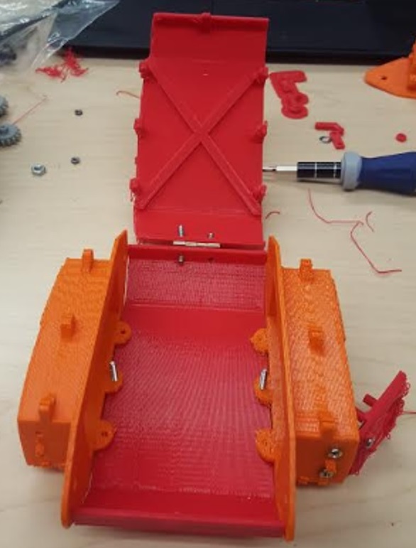
Figure 7 – 3D Printed Support Structure
Tracks
For the tracks, we initially 3D printed single track links to assemble and use for our Goliath tank. Unfortunately, the ABS 3D printed tracks were unreliable because it was fragile and did not provide the right traction that we needed, as shown in Figure 8.
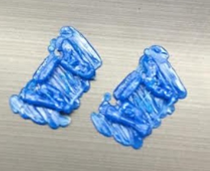
Fgiure 8 – Tracks
Upon speaking with the customer about this concern, he suggested that we speak to Mike Pluma about printing the tracks with SemiFlex material. I considered this suggestion but later realized that the tracks would take up more print time, but we only had about half an hour remaining. This realization resulted in purchasing the Tamiya tracks and wheels set, which provided an all in one rubberized track that had enough traction and saved us from using any more of our print time. This meant that the dimensions in width had to change in order to compensate the width of the new tracks and sensor door. We increased the width by 0.75 inches and kept the length and height roughly the same. Since we would like to have the tracks look like the actual 302 Goliath, we chose to cut the Tamiya tracks and have it sport a more angled appearance as shown in Figure 9.
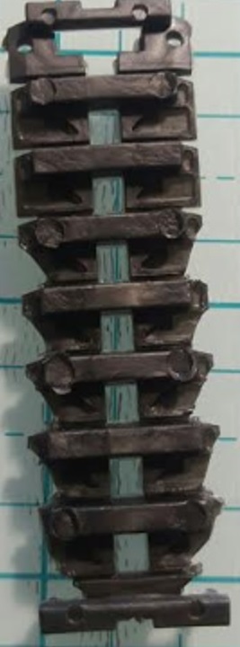
Figure 10 – Tamiya Tracks Cut
For the wheels, we decided to have the small wheels rotate instead of being idle. By doing so, we changed the design to a suspension-like appearance just as the actual 302 Goliath. The original Goliath suspension wheels are in Figure 10.
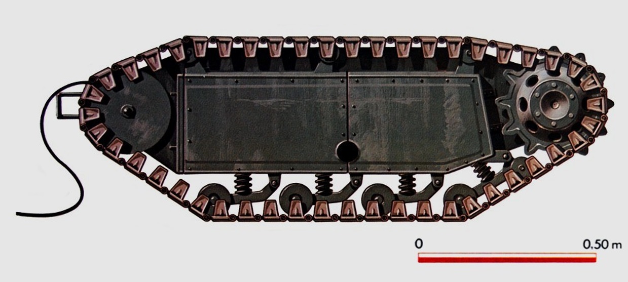
Figure 10 – Goliath 302 Suspension Wheels
Our modeled version is in Figure 11.

Figure 12 – Model Version of Suspension Wheels
Conclusion
Overall, our CDR consisted of many changes to our design which allowed the design process to move forward. Implementing the sensor mounts and tracks will prepare us to achieve the mission objective and play the game.
Preliminary Sketch
After researching the previous semester’s Goliath design, we created our own initial design based on the size of the Samsung Galaxy S6, the 3Dot board, two motors, I2C shield, and the actual design of the 302 Goliath.
The first step of the design process is the preliminary sketch design of the Goliath. This process includes researching the 302 Goliath’s architecture, in which we found pictures and blueprints from the German Engineers w/ Goliath Demolition Vehicles 1:35 ’39 – ’45 Series shown in Figure 1 below [1].
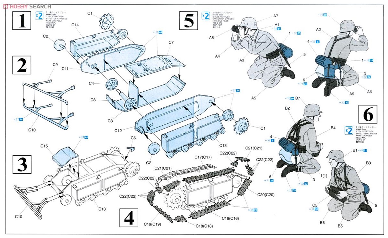
Figure 1 – Blueprints of Goliath
With this blueprint, I was able to sketch the side panel, top panel, bottom panel, side box with wheels and tracks of the Goliath shown in Figure 2 below.
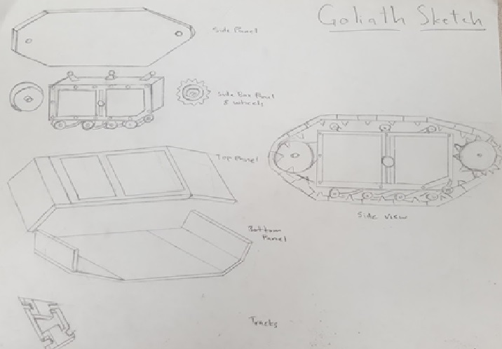
Figure 2 – Goliath Sketch
Calculations of Body Dimensions
The second step of the design process is to create a “back of the envelope” calculations regarding the body’s dimensions. Taking the dimensions of the Goliath 302, 1.5m x 0.85m x 0.56m, LxWxH, I calculated the ratio that is needed, which is 1×0.567×0.37 as shown in Figure 3 [2].
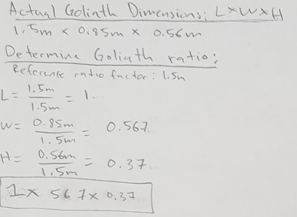
Figure 3 – Goliath Ratio
Since we decided to have the Samsung Galaxy S6 incorporated inside the body of Goliath, the basis of our dimensions were dependent on the size of the phone which is 5.65 x 2.78 x 0.27 inches [3]. For the electronic components, we initially decided on using the Tamiya Double Gearbox which has a dimensions of about 3 x 2.25 x 1.125 inches [4] and the 3DOT Board with battery is measured at approximately 2.75 x 1.5 x 0.75 inches. Also, we used the previous semester’s PCB board as an estimate of our potential PCB board, which measured at about 1.5 x 1 x 0.75 inches. All those not referenced to a link were hand measured by me. With the dimensions of the electronic components and the smartphone we determined the length of our initial design to be at 8.5 inches. This referenced length of 8.5 inches allowed us to calculate the width and height of our Goliath by using the ratio we calculated in the research blog post as shown in Figure 4.
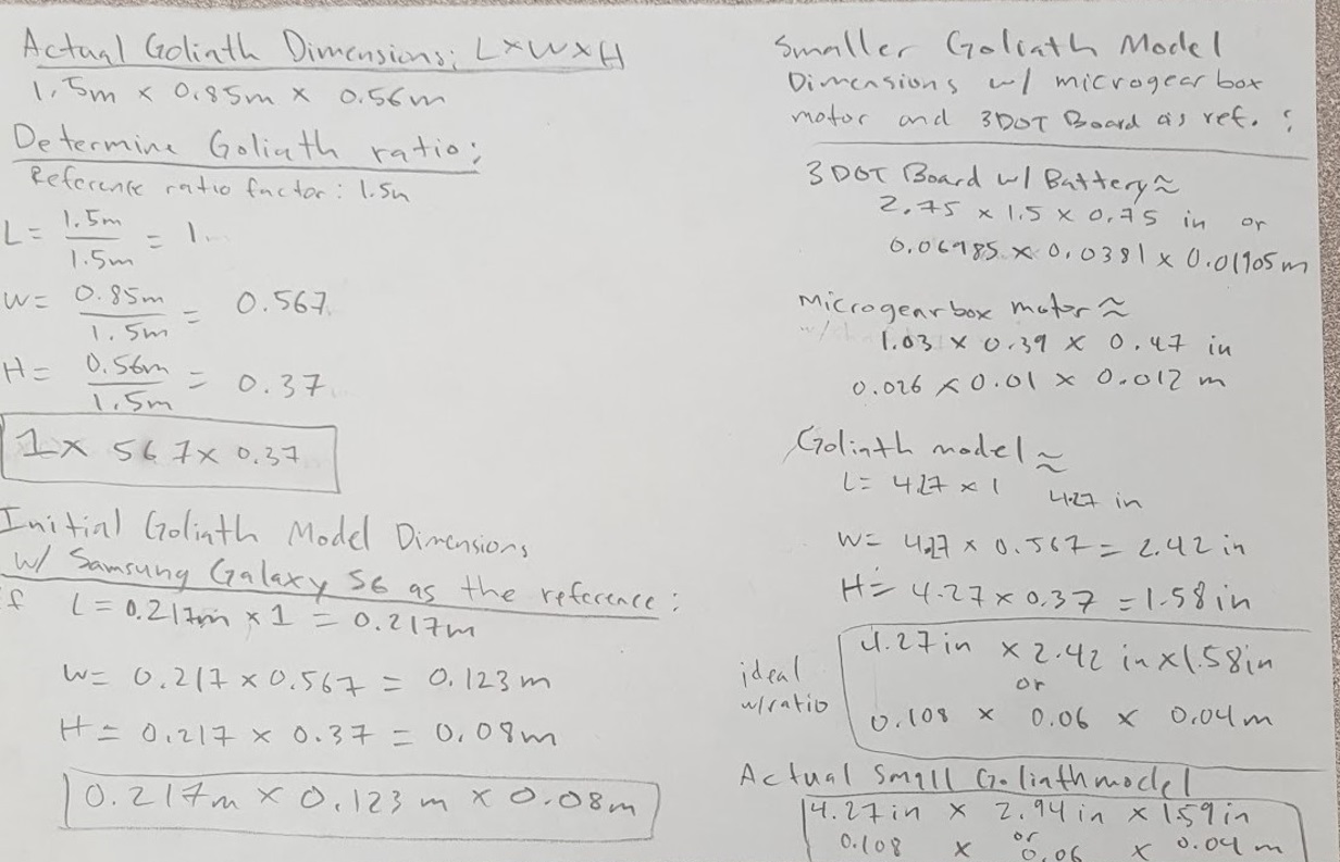
Figure 4 – Goliath 2016 Dimensions
In comparison, our initial dimensions of 8.55 x 5.06 x 3.21 inches was very close in approximation with the ideal dimensions of 8.55 x 4.84 x 3.19 inches with a percent error of 0 x 15.7 x 0.62 %. The calculations are shown in Figure 5 below.
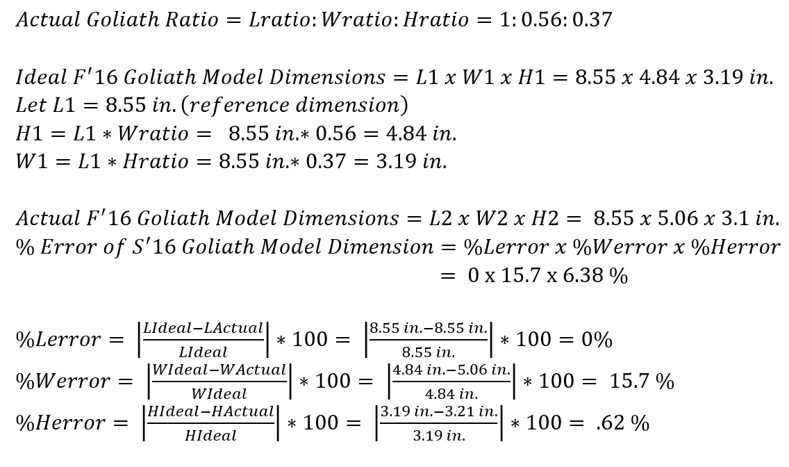
Figure 5 – Goliath Percent Error
The width of our initial dimensions is larger than the ideal dimensions because we needed to compensate the width of the phone including the width of the side box part, which uses up about 2 inches of the total width of the overall Goliath. A physical scaled model was created with cardboard for the purpose of mimicking the dimensions in real life as shown in Figure 6.
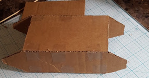
Figure 6 – Cardboard Goliath model
Goliath Fall 2016
Preliminary Design Document
Kristen Oduca (Project Manager)
Diana Nguyen (Missions, Systems, and Test Engineer)
Sou Thao (Electronics and Control Engineer)
Dylan Hong (Design and Manufacturing Engineer)
#1: Welcome to TRC “The Robot Company”
[expand title=”Lab Task” tag=”h4″]
- The Robot Company Work Breakdown Schedule
- Over the semester it is critically important that you understand what your responsibilities are within the project. Just as important is an understanding of the roles and responsibilities of your fellow engineers. To gain this knowledge and to help you find your place in the class, please read The Robot Company Job Descriptions.
- Write and Submit Cover Letter and Resume
- Help on your first Writing Assignment / Job Application
- Functional versus Written Cover Letter
- Beckman Coulter Resume Writing and Interview Skills
- Sample Cover Letters and Resumes
- Grading Rubric
- Your cover letter and resume should be in a single pdf document. The name of the document should be your name Joe Smith.
Submit your cover letter and resume in your EE400D Beachboard Dropbox, no later than Wednesday Noon.
[/expand]
#1: Welcome to TRC “The Robot Company” Part II
[expand title=”Lab Task” tag=”h4″]
- The Task Matrix
- Creativity Exercise
- Creativity Presentation Example
- Remember…
- The presentation should illustrate the evolution of a “crazy” idea (Hover Board” to a practical solution (magnetic levitation).
- All creativity methods (Dunker diagram, attribute listing, and lateral thinking) should be integrated into Brainstorming Approach (not assigned to individuals)
- Tour of the Cabinets
[/expand]
[expand title=”Creativity Exercise” tag=”h4″]
- Applying what you learned in the Creativity lecture to help the customer define the mission. Develop your creative solutions using the following methods.
- Dunker Diagram
- Brainstorming Approach
- Attribute (Properties) Listing
- Lateral Thinking
- Forced Relationship Technique
- Different Point of View
- Assign one team member to be the moderator for one of the creativity tools. The entire team must participate with different team members trading off as the moderator.
- The creative process is iterative, with one idea (often impractical) leading to another. For example; Create an innovative alternative to IR lights used to reflow solder surface mount devices (SMDs) onto a printed circuit board (PCB). This traditional approach does not provide uniform heating of the board, resulting in burnt boards on one side to cold solder connections on the other side of the board. Camp Fire – used to fire clay over 16 thousand years ago, lead to kilns lined with fire bricks, use fire bricks with electric heating elements to generate a uniform IR source for reflow soldering.
- Identify representative solutions developed by the group which are out-there and innovative. Avoid existing “known” solutions for solving the problem. If applicable, highlight (star) two (2) and not more than four (4) promising design solutions for each problem.
- Do not be concerned that you will be required to implement these solutions. Consider these alternatives ideas to be weighed against more traditional non-innovative solutions (see next bullet point).
- Make a list of questions/experiments that might help you determine the best solution for each problem. This list should contain both innovative and traditional non-innovative solutions.
- Document your work in a PowerPoint presentation to be given next week. The moderator should talk about the creativity tool for which he/she was the moderator. Grades will be assigned on an individual basis.
Presentation Outline
Prepare 1 slide per subject, with the total not to exceed 8 slides and take no more than 8 minutes to present.
For grading purposes, please follow this outline exactly, do not deviate.
- Candidate and Selected Problem(s)
- Dunker Diagram
- Brainstorming Approach
- Attribute (Properties) Listing
- Lateral Thinking – Forced Relationship Technique
- Lateral Thinking – Different Point of View
- Promising innovative alongside traditional solution(s).
- Questions/experiments that might help you determine the best solution(s).
Case Studies
- Prosthetic Arm
The Prosthetic Arm used the Dunker method to discover the VA hospital solution (do not have an amputee, do have an amputee)
- Pathfinder Solar Panels
Make solar panels lighter (based on incorrect problem statement), make solar panels heavier – move cg lower so it does not tip over. In this case study, the Dunker method helped the team discover the real problem.
[/expand]
#2: The Engineering Method
Quote(s) of the Day
“Each week (day, hour,..) is less important than the week (day, hour,…) before.”
Choose the difficult task first. Crust of bread
Critical Thinking ….Work independently
Streamlined the course
“…I hit the interview with Northrop-Grumman out of the park. I had the one interviewer leaving the room saying he wanted his money back from his undergrad after hearing about the content I learned being in 400D.”
Old Business
New Business
Assignment Due Dates
[expand title=”Lab Task” tag=”h4″]
S’18 Deliverables (From the Syllabus)
- There will be a single Design Review Presentation, incorporating elements traditionally found in Conceptual, Preliminary (PDR), and Critical (CDR) reviews.
- Management Grade is assigned by the instructor after consultation with instructional assistant, company president and/or quality control engineer, project and line managers (peer review).
- The Documentation Grade is defined by the Task Matrix with links to individual Blog Posts, including the Final Blog Post.
- The Mission Accomplished grade is defined by the completed Verification Test Plan/Report, accompanying Project Video and Validation of the Project
- Over the duration of the course, assessment opportunities may come up from time to time. These “assessments” include your cover letter and resume, plus quiz grades, and others, will make up the Miscellaneous Grade.
Research
- “Engineers should always try to build on what has already been done before. Information on related problems that have been solved or unsolved may help engineers find the best solution.”
- Working from your job description, review Blogs linked to in the Task Matrix.
- Step 1: Project Managers (morning) or Division (afternoon) Manager assign blog posts to engineers.
- Step 2: Read the blog post assigned to you. Add notes (NOT comments) to “Blog Post Value” column if you want to remember something.
- Step 3: Place a value 0 – 4 on the blog post
- Step 4: After reading the blog posts and thinking about what is needed for you to implement the project, make a list of tasks that you believe are missing. Do not add to the Task Matrix yet. Bring hard copy version to next class/lab.
- Step 5: As a cautionary tale, read over Case Studies.
Blog Post Value
Rate the value of the blog post with respect to progressing the design to a product.
- [0] No help
- [1] Little help. May be able to use part(s) in another blog post.
- [2] Some help. May provide a foundation for a future blog post.
- [3] Provides a good foundation on which to build a great excellent blog post.
- [4] No changes needed. We can move forward from this blog post.
Meet with Project Managers
- Creativity Exercise
- Clarification of the Customer’s Expectations, including the program objectives, constraints, design drivers, mission profile, and criteria for defining mission success.
Meet with JPL Subgroup
- Identify Project and preliminary list of questions.
Research Case Studies
- Case Study – Pick and Place
- After a suggestion was made that a Makeblock XY – Plotter could be an excellent platform on which to build a pick and place machine, the team immediately purchased the plotter and modifying it to be a pick and place machine. In the end the project achieved all its goals.
- Lesson: While it is hard to argue with success, and in this case showing the initiative to move forward as quickly as possible, two problems present themselves. The purchase of this $300 dollar plotter was not approved by the department and therefore the students may have had to fund the project. If the plotter did not meet design requirements, and in multiple instances it did not, the students again would have had to fund the project. Instead of focusing on the strawman solution the students may have wanted to do their homework, and may have found in less than an hour, the PP4 – SMD-Pick and Place Machine and Paste Dispenser. This DIY project includes a pdf file listing all the components needed to make the project.
- Case Study – Project BiPed Robot
- For 12 weeks the software engineer was stopped by a single broken link on the Project BiPed website. After the Critical Design Review (CDR) and a few minutes of detective work the Project BiPed RoFi software download page was found.
- The software plus documentation was also found on the previous semester’s last blog entry – the first one the software engineer should have read.
- Lesson: First, do your homework and then if you still need help getting past a problem talk to your management team.
- Case Study – Velociraptor
- The core software engine used by walking robots like Biped and Velociraptor are the same. For 15 weeks these two teams never spoke to each other.
- Case Study – SpiderBot
- After being given a HEXBUG robot, the spider robot team took the HEXBUG apart, rendered all the parts in Solidworks and then after 12 weeks of hard work, realized it could not be duplicated using available 3D printers. After a few minutes on the internet, three 3D printable spiders designed by Jerry Mantzel, Joe Klann, and Theo Jansen were located. Ultimately, an original design was implemented in only a few weeks.
- Lesson: First, do not focus on the first “strawman” solution presented to you. Follow the engineering method beginning with doing your homework. Second, the whole team needs to sign-off on the final design concept. In this example, the mechanical engineer should have understood the limitation of the fabrication tools available to his/her project and brought these limitations to the attention of the team.
- Case Study – Rover
- The sum total of the design at CDR was two 3D printed sheets of plastic – one included two bends. Further, the prints were not coordinated with the Division manager or was funding approved by the department.
- Lesson: The mechanical engineer did not do their homework, which after only 15 minutes research would have found reference models. Next, the wrong machine (3D printer) was used. In addition, the engineer should have requested help from the Division manager in locating the correct machine (laser cutter). Finally, without approval the student may have had to pay for these 3D prints.
[/expand]
#3: High Level Requirements
Old Business
New Business
Assignment Due Dates
[expand title=”Lab Task” tag=”h4″]
- Customer Objectives (Shared Google Document)
- Draft of Level 1 Requirements
- Training Plan (Shared Google Document)
- Robot Kit (Shared Google Document)
- Review of the reference blog posts
[/expand]
[expand title=”Requirement Evaluation Rubic” tag=”h4″]
- Is the requirement, Quantitative, Verifiable, and Realizable?
- Is the requirement located at the correct level (1 – Program/Project, 2 – System/Subsystem)
- Is the requirement response to a higher level requirement or customer’s objective (Requirement Flow Down)? Is the linkage clearly defined?
- Does requirement provide links to the source material?
- Does the requirement move the design process forward?
- Are equations used to calculate a requirement provided and are answers correct?
- Is language in the form of a requirement?
- Avoid multiple requirements within a paragraph. (i.e., breakup statements that contain multiple requirements)
- The requirements that are missing are the hardest to discover and will be factored into your evaluation. Use your strawman design to help you find them.
[/expand]
#4: Level 2 Requirements and Modeling
Old Business
New Business
Assignment Due Dates
[expand title=”Lab Task” tag=”h4″]
- S’18 Google Training Document
- Projects should continue to work on Task Matrix and Level 2 Requirements.
[/expand]
Design and Manufacturing Resources Overview
- 1. 3D Models and Simulation
- 1.1 Qualifications
- 2. Manufacture Parts and Assemblies
- 2.1 Off-the-Shelf Parts
- 2.1.1 Case Study
- 2.2.2 3D Printer
- 2.1 Off-the-Shelf Parts
- 3. Support Equipment
3D Models and Simulation

Task Summary:
- Use CAD/CAE software to design the robot
- Use CAD/CAE software to design the mechanical parts
- Run static and dynamic simulations
The successful candidate(s) will use a solid modeling computer-aided design (CAD) and computer-aided engineering (CAE) software program, typically SolidWorks, to design the mechanical parts, subassemblies, and even the robot itself. The overall design must take into consideration all parts manufactured and purchased. The most commonly forgotten parts are the connectors and cabling.
Working with the systems engineer, determine the acceptability of the design by running simulations. These may be in the form of system-level animations (e.g., for bipedal robots the walking motion while tracking center of mass), system level load and shear analysis (e.g., for spiders a stress analysis across the body-servo-leg interfaces), and others as seen appropriate.
Qualifications
Work experience with a 3D modeling program or a desire to learn is a plus. Preferred modeling program is Solidworks; however, a working knowledge of Blender, AutoCAD, SketchUp or any other CAD/CAE program will be taken into consideration.
Manufacture Parts and Assemblies

Task Summary:
- Manufacture mechanical parts
- Become familiar with 3D printing process, operate 3D printer
- Learn to use the laser cutter
- Aid in physical PCB design
- Specify, source and order off-the-shelf parts
Parts may be fabricated using additive (3D printers), subtractive (CNC, laser cutter, lathe …), or other (vac-u-form, molds …) manufacturing techniques. It is important to work with the manufacturing Division Manager to find the manufacturing technology required for the project.
Off-the-Shelf Parts
Specify and order miscellaneous parts including:
a) Fasteners – nuts, bolts, screws, washers…
b) Adhesives and Sealants – tape, velcro, zip-ties, O-rings, weather stripping, silicone tube…
c) Powertrain Components – belts, gears, bearings…
d) Hardware – grommets, brackets…
The customer has a large number of fasteners, powertrain components, and other hardware. Otherwise, purchase such parts from Home Depot and McMaster-Carr among others
Case Study
The manufacturing engineer of a robot has a friend with a 3D printer. He asks his friend if she will print the parts for their robot. The friend agrees, assuming that the STL files will be provided within a few weeks.
Case 1: Near the end of the semester, the friend receives the STL files and realizes that they simply do not have time to print the parts. What should the manufacturing engineer have done to avoid this problem?
Case 2: The STL files are provided within a few weeks. However, the friend says her 3D printer is broken and she simply does not have time to fix it. Because the engineer now has time to recover from this disaster, instead of running around asking everyone if they have a 3D printer or purchasing time on a 3D printer, he contacts the Division Manager for help. The Division Manager bring up the problem at the next division meeting and another 3D printer is located. This is the strength of the matrix organization!
3D Printer
In the process of creating rapid prototyping designs and learning design constraints, the operation of a 3D printer is required. Learning the process of generating STL files, loading/managing a 3D printer and finishing 3D print surfaces is the task of the manufacturing division.
Support Equipment

Task Summary:
- Provide equipment support to project members
- Generate test equipment and locate necessary parts
During the design and development phase, E&C engineers will need to test electronics. The manufacturing engineer shall provide support in the design and fabrication of any Bench Test Equipment (BTE), Ground Support Equipment (GSE), and Test Jigs on an as needed basis.
Project Name/Semester/Year
Title of Post
Author/s:
Verification:
Approval:
Introduction
Contents
Body/Section Title
Contents
Body Subsection (If needed)
Contents
Body/Section 2 Title (If needed)
Contents
Body 2 Subsection (If needed)
Conclusion
Content
References/Resources
- Link 1
- Link 2
- Etc..
Mark Huffman (Project Manager)
Vanessa Enriquez (Manufacturing Engineer)
John Ocampo (Electronics and Controls Engineer)
Nornubari Kanabolo (Missions and Systems Engineer)
Mission, Systems and Test Timeline

Mission, Systems and Test Overview
- 1 System Design, Integration and Test
- 1.1 System Design
- 1.2 Requirements
- 1.3 Integration and Test (Requirement Verification and Product Validation)
- 1.3.1 Look for the Intangibles
- 1.3.2 Case Studies
- 2. Mission and Application Customization
- 3. Interface Design and Resource Tracking
- 3.1 System Electronic Interface Design
- 3.2 Power Distribution Strategy
- 3.3 Interface Control Document (ICD)
- 3.4 System Resources
Week #1 – Welcome to The Robot Company
This is the first week of the semester, so the MST division manager does not yet know that he or she is the MST division manager. The course objective is explained by the instructor and the class is introduced to The Robot Company and the matrix concept. Students apply for jobs to be announced in the next class meeting. Applying for MST division manager does not guarantee the position. In the same vein, failure to apply for MST division manager does not take one out of the running for the position. If one is interested in applying for the MST division manager position, he or she should carefully read The Robot Company Work Breakdown Structure document (file name: Job Descriptions) with close attention paid to both the “Division Manager” and “Mission, Systems, and Test Division” sections.

Week #2 – Introductions, Schedules, and Contact Information
Training Goals
- Appoint 1 consistent meeting minutes secretary
- Get everyone’s contact information, engineering backgrounds, and engineering work experience
The first MST division meeting is held in class. The manager will take minutes of this meeting, but a recording secretary will be appointed for future meetings[1]. Meet the members of the division, and obtain their contact information: first and last names, preferred email addresses, and phone numbers. This information should be added to a spreadsheet that all MST division members can access. Ask each member to give a brief introduction of his or herself and explain their project interest within The Robot Company. It may also be helpful to survey the experience level and interest level of the division members.
Outside of the meeting, create a spreadsheet so that each division member (including the manager) can post their availability. Google Sheets from Google Drive is recommended because individuals can easily access the spreadsheet and make updates in real time. This is useful for scheduling the required weekly division meeting and can also be utilized to quickly schedule one-on-one meetings. Once all schedules are added to the spreadsheet, announce the next meeting date and time.
It is the division manager’s responsibility to assess the members of the MST division. Google Sheets has an Attendance and a Grade Book template, both of which can be customized to fit most needs.
[1] If I were to do this again, I would have everyone take minutes of the first meeting and appoint the recording secretary based on the most accurate and well formatted minutes. I do not recommend rotating the recording secretary position.
Week #3 – Fundamentals of System Engineering
Training Goals
- Appoint 1 consistent meeting minutes secretary
- Get everyone’s contact information, engineering backgrounds, and engineering work experience
Non-Technical Training
The roles and responsibilities of the systems engineer are critical to project success. The NASA Systems Engineering Handbook, which is the required textbook of the class, is an MST engineer’s bible. Chapter 2 of the book covers “Fundamentals of Systems Engineering,” which is adapted to a PowerPoint by the division manager and presented at the meeting. In addition to translating the information in the chapter into a presentation, apply the information to the EE 400D class structure and the objectives of The Robot Company. The chapter has an “Example Premise,” which is assigned for outside reading. Quiz 01 tests the division members on this reading. The quiz is created using Google Forms on Google Drive.
It is also important to set Division Manager Expectations at this first formal meeting:
- Any failure/poor work shown at PDR, CDR, the final exam, e.t.c. in the MST division ultimately reflects on the division manager.
- We are all in this together; all trying to get a good grade, and pick up some valuable classroom experience for when we graduate and work in the industry.
- Ask the division manager for HELP, IT’S THEIR JOB TO HELP
- Training is important, but it can prove to be fruitless if work is not checked and feedback is not provided. After training sessions, DM will be assigning hard deadlines for division members to turn in some of their work so that DM can check if members are on the right path. DM will provide feedback the following week so that division members have sufficient time to correct their work.
- The DM required to quiz you guys; expect 3-4 quizzes this semester, open NASA handbook, open MST Lectures. Quizzes show the professor that the DM is teaching you, as well as showing him that you all are engaged, paying attention, and absorbing what is being taught
Inquire as to whether the division members have access to an Arduino board. They will need a board to complete further training. This week, complete the “Introduction to Arduino” training.
Week #4 – Technical Requirements Definition
Training Goals
- Quiz on last week’s lecture (As created by the DM)
- Introduce requirements
- More on using Arduinos; introduce Arxterra Firmware as well
Non-Technical Training
“Why projects have failed in defining requirements has been a direct result of not having enough time to cover requirements definition.” – Professor Gary Hill
Chapter 4, section 2 of the NASA Systems Engineering Handbook covers “Technical Requirements Definition.” This is an integral part of the project process and must be covered in detail. Create a PDF lecture based on this section of the book. Reference “Appendix C: How to Write a Good Requirement” for more information. It may also be helpful to cover the section titled “Requirements Creep” from section 6.2.1.2. MST division members should be in the process of writing their requirements at this point of the semester. In order to make this lecture more interactive, have the members work in groups of two. They will each choose one of their requirements and apply the “Editorial Checklist,” “General Goodness Checklist,” and “Requirements Validation Checklist” from Appendix C to the requirement.
Assignment 01 requires the division members to apply the three checklists to all of their existing requirements. They must submit their before and after requirements prior to the next division meeting. Alternatively, the group could do this as an exercise during the meeting in order to utilize the division manager and other members as resources while editing their requirements.
The Systems Engineer is responsible for three aspects of the software. The command decoder, commandHandler (commands), and the sendData (telemetry). A major aspect of this responsibility is understanding and modifying the existing Arxrobot firmware in the Arduino IDE for application to his or her specific robot or project. In this training, the systems engineer will work through existing Arduino IDE example sketches and make modifications to get comfortable with the IDE and the process of understanding and modifying existing code.
It is also important that the division members being familiarizing themselves with the existing Arxrobot firmware (available for download through Github) in preparation for next week’s technical training on commands and telemetry.
The Arduino Training/Intro to Arxterra can be utilized, but an important note: as of Spring 2017, the Firmware has been upgraded. MST engineers can use the upgraded 3DoT firmware software folder (Arduino/3DoT firmware is almost identical). It is easier to use because unlike the older Arduino firmware that requires the user to toggle back and forth through the various code tabs.
Week #5 – Product Breakdown Structure
Training Goals
- Quiz on last week’s lecture (As created by the DM)
- Introduce PBS and WBS
- Introduce Resource Allocation Reports; **IMPORTANT**
- Go over Arxterra Firmware Commands and Telemetry; **IMPORTANT**
- Assist members with PDD work
Non-Technical Training
Chapter 4, section 3 of the NASA Systems Engineering Handbook titled “Logical Decomposition” includes a section that briefly covers the Product Breakdown Structure (PBS.) Chapter 6, section 1 titled “Technical Planning” includes a section that explains the relationship between the Work Breakdown Structure (WBS) and the PBS. The PBS is the responsibility of the systems engineer. There is not quite enough information between these two sections to create a long presentation; instead focus on first going over the info, and then work with your division members to create an example PBS during the meeting.
Reference NASA SE Handbook Sections 4.2, 4.3-2, 6.1-4/5,G-1
This week will teach the MST division about commands and telemetry in the Arduino IDE. First, a lecture on commands and telemetry in reference to the document and PowerPoints. Have the group work through it on their own. This will add to their meeting contribution points. Show the software block diagram to demonstrate where the line is between systems and electronics engineering. Each projects systems engineer will need to determine which commands their project will be utilizing.
Explain resource reporting and explain the information that must be included in the report. There are three main types (possibly more) of resource reports: budget, mass, and power. Update the current template so that the members can reference and customize for their project. Resource reports are critical for keeping the project within cost, mass, and power allocations.
Week #6 – Design Solution Definition
Training Goals
- Quiz on last week’s lecture (As created by the DM)
- Go over Design Solution Definition process
- Go over firmware: block diagram, control panel, custom commands, LRC bytes, and Bluetooth communication
- Go over PDR
Non-Technical Training
Chapter 4, section 4 of NASA Systems Engineering Handbook covers the design solution definition. This is where systems engineers can learn to “look for the intangibles” as mentioned in The Robot Company Work Breakdown Structure. This section has been adapted into a document to be presented at the division meeting. As an interactive exercise, work with a design solution from a previous semester project that is not being implemented this semester. As a group, brainstorm (using a technique from week 03 in class creativity lecture) alternative design solutions. Work through the “Design Solution Definition Process” with this example.
The Preliminary Design Review is typically scheduled for week 07.
PDR is one of the most important (if not the most important) MST division events. Most of the work done (80%) is systems engineering work, so MAKE SURE YOU UNDERSTAND THAT.
Demonstrate the Arxterra App in RC mode using a mobile device or tablet. Connect to the Arxterra Control Panel on a computer and explain the communication process between the control panel, mobile device and the Bluetooth module (in community mode). Show the division members how to access the ArxRobot firmware and what to do with it. Make an example in the firmware using an existing command and demonstrate it to the group. Make a custom command and demonstrate how that works, too. This process shows the connection from the code, to the Arxterra app, to the Bluetooth device.
Explain how the LRC byte is calculated in the command and telemetry packets.
There will also be a skill assessment this week based on the previous weeks’ Arduino Technical Trainings. Division members may be allowed to refer to a reference packet during the skill assessment, if the division manager so chooses.
Week #7 – Product Verification & Firmware Setup
Training Goals
- Quiz on last week’s lecture (As created by the DM)
- Go over product verification process
- Write firmware
Non-Technical Training
Chapter 5, section 3 of NASA Systems Engineering Handbook covers the product verification process. Systems engineers are responsible for creating the test plans for their respective projects. A PowerPoint presentation has been created explaining the processes and procedures for project verification. If the group has started on test plans and checklists, have them work in pairs to edit their work based on the material covered in the meeting. If the group has not yet started on test plans and checklists, have them each turn one of their requirements into a row in the “Simplified Requirements Verification Matrix” from Professor Hill’s lecture 02. Reference “Appendix D: Requirements Verification Matrix” and “Appendix I: Verification and Validation Plan Sample Outline” for more information.
During this meeting, division members will work on using the Arxrobot firmware for their individual projects. They can utilize the other members and the division manager as a resource at this time. The links in week 06 (above) will also be useful as references this week.
Week #8 – Product Validation & Cable Tree/Cable Routing Diagram
Training Goals
- Quiz on last week’s lecture (As created by the DM)
- Go over product validation process
- Go over cable tree/routing diagram
Non-Technical Training
Chapter 5, section 4 of NASA Systems Engineering Handbook covers the product validation process. This section further explains the difference between verification and validation, as does the previous section. Create a PowerPoint or PDF to explain the product validation process to the division. As a group, brainstorm ways in which their products can be validated and different aspects of the validation process as it applies to EE 400D and The Robot Company. Reference “Appendix E: Creating the Validation Plan” and review the “Validation Requirements Matrix” for more information. Fill out a row in the “Validation Requirements Matrix” based on the brainstorming session.
As of Spring 2017, there is a new, streamlined Test Plan for the class. The template contains an integrated Pass/Fail and Traceability Matrix while the old Goliath Example one has those as separate sections in the Test Cases, use the Template Integrated Matrix.
The cable tree/cable routing diagram is a responsibility of the systems engineer. Explain the difference between a wiring diagram and a schematic. MS Visio and Google Drawings in Google Drive work well, and most of the EE computer labs have MS Visio installed. The systems engineer should obtain a 3D model of the project from the manufacturing engineer in order to complete this document. The systems and manufacturing engineers may decide how much of this document the manufacturing engineer takes on, depending on their strength in SolidWorks. Regardless, it is the system engineer’s job to account for the physical layout of the wiring and connectors in the project. Create a simple wiring diagram to use as an example.
The division manager may want to hold another Arxterra firmware/app/control panel workshop for the division to have the opportunity to work together.
Week #9 – Repeating Lessons and Beyond
Training Goals
- Quiz on last week’s lecture (As created by the DM)
- ICD
- Repeat Verification/Validation Training
- Go over cable tree/routing diagram
- Go over more Arxterra/Custom Command/Telemetry/3DoT customization material
Non-Technical Training
At this point in the semester you have covered most of the curriculum you were required to cover already. Division meetings must now be tailored per meeting to provide the resources/ training as the MST engineers need. This will most likely mean repeating training on Verification/Validation, Test Matrices, Test Plan Content, CDR, Cabling Tree, and Arxterra. To better gauge the class’s MST needs, meet with all project managers and ask them the following 3 questions:
- How has the MST work on your project been so far?
- What future MST work does your project need (training, resources, etc.)
- How can I (as division manager) help your group meet your MST project needs and move your project forward?
These 3 questions will give valuable insight into every project’s MST needs. Consider meeting with every project manager 1x/week (during lab) and ask them the same 3 questions every class, to see how your MST engineers are doing, and how the projects are doing MST-wise.
Topics to repeat include Verification/Validation, Test Matrices, Test Plan Content, CDR, and Cabling Tree. ALSO GO OVER WRITING AN ICD IF YOUR MST ENGINEERS ARE DOING INTEGRATION.
Project Schedule
By Kristen Oduca (Project Manager)
Top Level Schedule
A motor trade off study was conducted to compare the specifications of a GM9 or a DG01D DC motor. From the results, the DG01D motor was more suitable for the 800 gram Goliath tank, and required less power to run. However, there is no indication as to which motor was selected, and how they narrowed down their search to these two motors. In contrary to the trade off study, the motor used does not look like the GM9 nor the DG01D. Through observation, the motor used on the final Goliath seemed to be a Tamiya Twin-Motor Gearbox RB-Tam-01. Also, by manually testing the speed of the Goliath, it was able to pass 4 feet in 38 seconds. Thus, the speed was calculated to be 1.26in/sec or 3.2cm/sec. As a result, by analyzing the speed of the Goliath and this trade off study, a new study should be performed to fully understand the specifications of a DC motor, and how to choose the correct motor.
System/Subsystem Level Task
- Perform trade off study on follower sensors: find the pros and cons of each sensor
- Select the best sensor based on trade off study
- Perform test on breadboard to verify sensors are working correctly
- Perform trade off study on choosing the right DC motor for Goliath
- Choose a DC motor based on analysis of speed, torque, current, and voltage levels
- Perform control tests on DC motor through Arduino IDE
- Integrate sensors and DC motor onto breadboard for test and validation
- Create Fritzing diagram required for PCB
- Program 3DoT Board to control motors based on feedback of sensors to automate Goliath’s movement
- Assist Systems engineer with interfacing the phone’s camera on the bluetooth module to provide live video feed
Burn Down and Project Percent Completion
- Continue to add other important parts such as the wheels, gears, tracks, and doors to the assembly of the 3D model in Solidworks
- Perform a tradeoff study between 3D printing, laser cutting, and vacuum forming to find out which material is best to work with. For instance, if we plan on 3D printing would we be able meet our print time requirement of six hours?
- Perform a tradeoff study between different periscopes
- Measure the overall weight of Goliath and inspect that the potential material is good enough withstand it while in motion.
- Cooperate with the Electronics Engineer and discuss PCB layout and assembly
NASA JPL


NASA JPL
Program Objectives/Mission Profile
By Kristen Oduca (Project Manager)
Objective
The Goliath will follow the biped autonomously throughout an unknown course with obstacles, such as walls and “hills” with a six and a half degree incline. Throughout the biped’s journey, the Goliath will remain behind the biped at a fixed distance. Through an Android phone, the Goliath will provide live video feed for the biped in the Arxterra application. This was based on the game plan created by the game committee the customer’s request.

Project Manager Overview
- 1. Project Definition
- 1.1 Qualifications
- 2. Project Schedule & Budget
- 3. Meetings
- 4. Blog Posts
- 5. Task Matrix
- 6. Assessment
- 7. Project Video
- 8. Final Documentation
Systems/Subsystem Deisgn
Project Breakdown Structure
By Diana Nguyen (Missions, Systems, and Test Engineer)
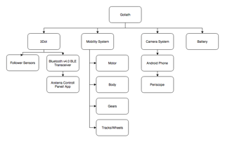
Product Breakdown Structure (PBS) is an outline of the product broken down into different systems. The systems can be hardware, software, or informational items. The Goliath is broken down into battery, camera, mobility, and the 3Dot board. The battery will provide power for all of the systems. The camera system will encompass a Galaxy S6 with a periscope attached. The components that contribute to the movement of Goliath are its motors, gears, and tracks. Lastly, the 3Dot microcontroller will be reading the inputs of the follower sensors and providing a Bluetooth transceiver to connect to Arxterra.
Electronic System Design
System Block Diagrams
By Diana Nguyen (Missions, Systems, and Test Engineer)
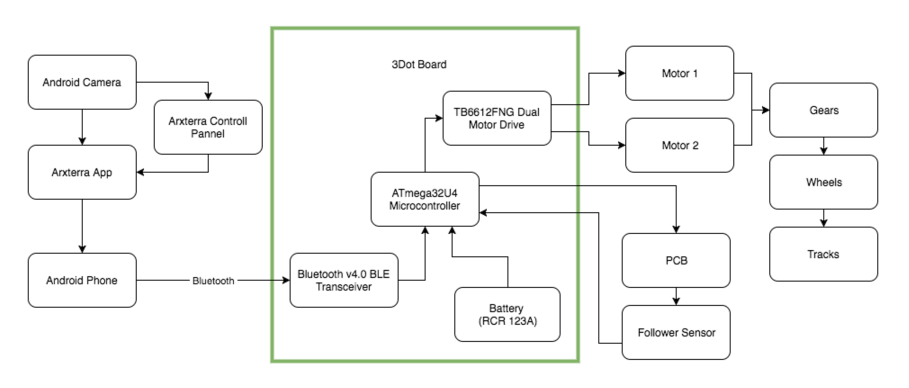 The system block diagram illustrate how the components of the Goliath communicate and interlink with each other. The new 3Dot board has a built in Bluetooth transceiver which eliminates the need to have a Bluetooth module. Using the Bluetooth transceiver we connect the Galaxy S6 to the 3Dot board which will allow us to provide a live feed while the phone is on Goliath. Also built into the 3Dot micro-controller is a rechargeable battery which powers to the board and all the components connected to it.
Interface Definition
By Diana Nguyen (Missions, Systems, and Test Engineer)
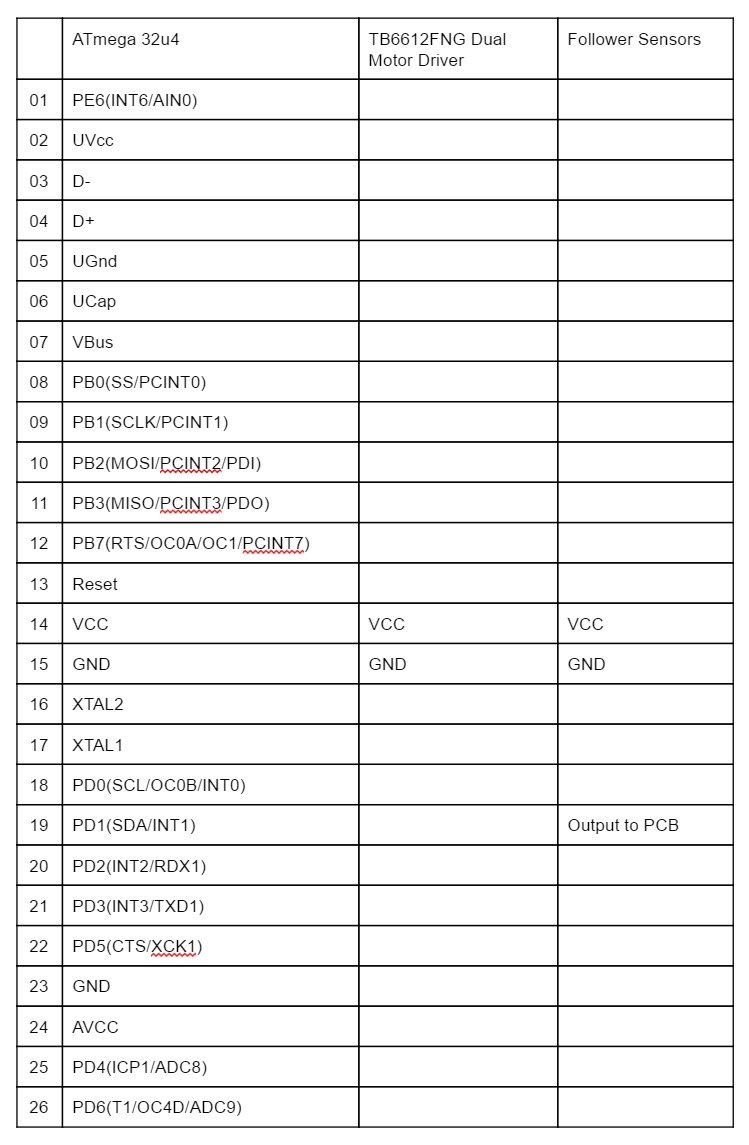
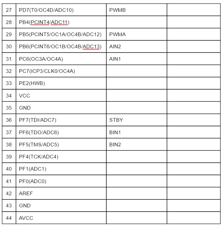
The interface matrix shows how each subsystem will be connected to the ATmeg 32u4 which is located on the 3Dot board.
Mechanical Design
By Dylan Hong (Design and Manufacturing Engineer)
According to the customer, the 3Dot Goliath tank must replicate the actual 302 German Goliath Tracked Mine as much as possible in terms of mechanical design. This preliminary 3D model of Goliath was created with Solidworks. By researching the 302 Goliath tank, I was able to create four individual parts: the top, bottom, and the two sides to assemble it in a way that replicated the actual product. The inside of the body is hollow and is made to fit the smartphone, motors, PCB board, 3Dot board, and the battery. [1]
As for the dimensions of the Goliath, the previous semester modeled the body with dimensions of 7.375 x 5.125 x 3.44 inches, which was disproportionate to the actual Goliath. Upon research, we found that the actual specification for the dimensions of the actual Goliath came out to be a ratio of 1: 0.566: 0.373. Our Goliath is currently modeled at 7.33 x 5.13 x 2.5, which is approximately closer to the actual ratio than the previous model. The only outlier from our dimensions was that the width has a difference of about an inch from the actual model because we have to compromise the width of the Galaxy S6 smartphone, which has dimensions of 5.65 x 2.78 x 0.27 inches.[3]