Construction Update 2.5
By Mustafa Alkhulaitit – Project Manager
and Gregorios Rios – 3S modeling
This a follow up to the previous blog posted. In this blog, I will be discussing in details how I got the LCD controller to work. As mentioned before, there were multiple issues associated with the LCD panel. This blog will be broken into different sections targeting the different issues.
1. Arduino IDE:
The first step is to make sure that the Arduino IDE is connected to the correct board. In our case, the board used is the “Arduino Mega 2560”
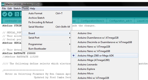
The other step is to make sure that the serial port is the one that the board is connected to. If the COM port is different, there will be no connection between the board and the computer.
The bottom right corner of the Arduino IDE states the board that the COM port is communicating with.

2. Firmware:
By downloading the Marlin firmware, the default motherboard was “7” and needed to be changed to “33” which is the board we are using.
// 10 = Gen7 custom (Alfons3 Version) “https://github.com/Alfons3/Generation_7_Electronics”
// 11 = Gen7 v1.1, v1.2 = 11
// 12 = Gen7 v1.3
// 13 = Gen7 v1.4
// 3 = MEGA/RAMPS up to 1.2 = 3
// 33 = RAMPS 1.3 (Power outputs: Extruder, Bed, Fan)
// 34 = RAMPS 1.3 (Power outputs: Extruder0, Extruder1, Bed)
// 4 = Duemilanove w/ ATMega328P pin assignment
// 5 = Gen6
// 51 = Gen6 deluxe
// 6 = Sanguinololu < 1.2
// 62 = Sanguinololu 1.2 and above
// 63 = Melzi
// 7 = Ultimaker
// 71 = Ultimaker (Older electronics. Pre 1.5.4. This is rare)
// 8 = Teensylu
// 81 = Printrboard (AT90USB1286)
// 82 = Brainwave (AT90USB646)
// 9 = Gen3+
// 70 = Megatronics
// 90 = Alpha OMCA board
// 91 = Final OMCA board
// 301 = Rambo
#ifndef MOTHERBOARD
#define MOTHERBOARD 33 // 33 is for Ramps 1.3 and 1.4
#endif
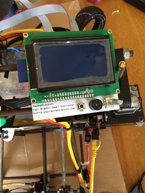
3. Hardware:
Connection pins had to be soldered on the RAMPS 1.4 in order to establish connection between the LCD controller and the RAMPS 1.4.
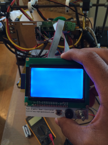
4. Power Issue:
Another issue we’re facing is dealing with the power supply. The LCD controller won’t remain ON when we disconnect the PC connection to the board. After some research, it appeared that the RAMPS 1.4 is missing a diode that would make the LCD controller on without the PC connection.
Therefore, 1N4004 diode will be soldered on the RAMPS 1.4, and that will solve the power issue.
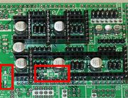
The middle indicated rectangle is where the diode going to be soldered.
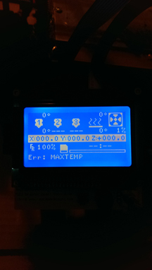
5. Conclusion:
Other than this, the LCD controller is a very neat feature that the printer is going to have. All of the other functions were verified like adjusting the axis, temperature, and the fans. After soldering the diode, the LCD controller will be a 100% working and ready to function without any issues.