Spring 2018 AT-ST Preliminary Model

By: Danny Pham (Manufacturing Engineer)

Verified By: Intiser Kabir (Project Manager)

Approved By: Miguel Garcia (Quality Assurance)

Table of Contents

Introduction

Our initial design included a similar concept to the Titrus III robot that involved moving the robot with servos. Since this was not ideal, we redesigned the legs to move using dc motor instead of servos and keeping the servo as a weight shift mechanism. Our design was inspired by previous velociraptor projects and an actual biped walking Theo Jansen kit.

Initial Model

For our new design, we switched from a Titrus III leg design to the Theo Jansen design. We went with the Theo Jansen design because this design works much better when it is connected to a motor and the leg can rotate in a continuous motion.

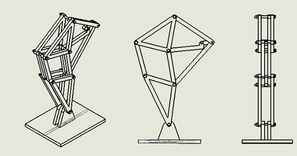
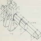
Figure 1: Theo Jansen Leg model

Description

This is the Theo Jansen design. It incorporates a motor that rotates a gear that in turn rotates a shaft connected to the leg. This will rotate the rest of the leg and create a circular walking motion for the foot. This will allow the robot to take a step.

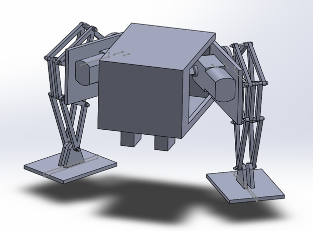
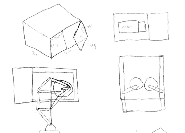
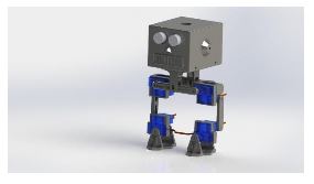
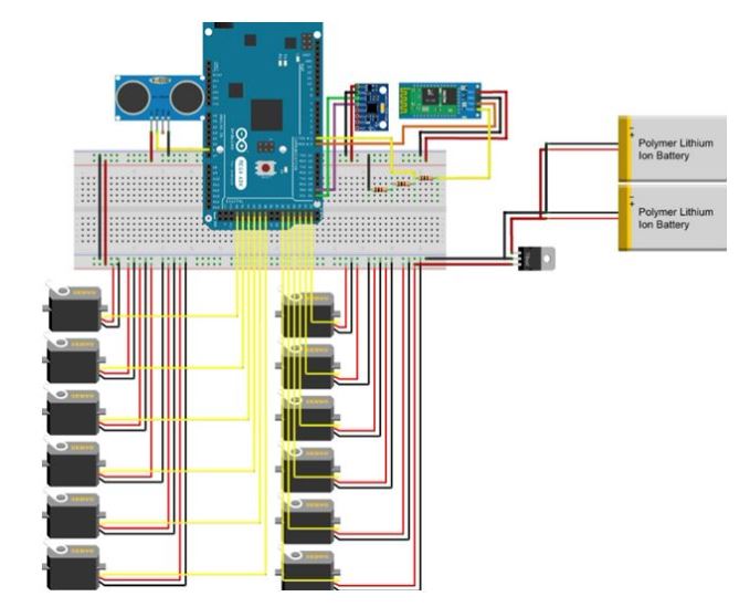
Figure 2: Preliminary Model

Description

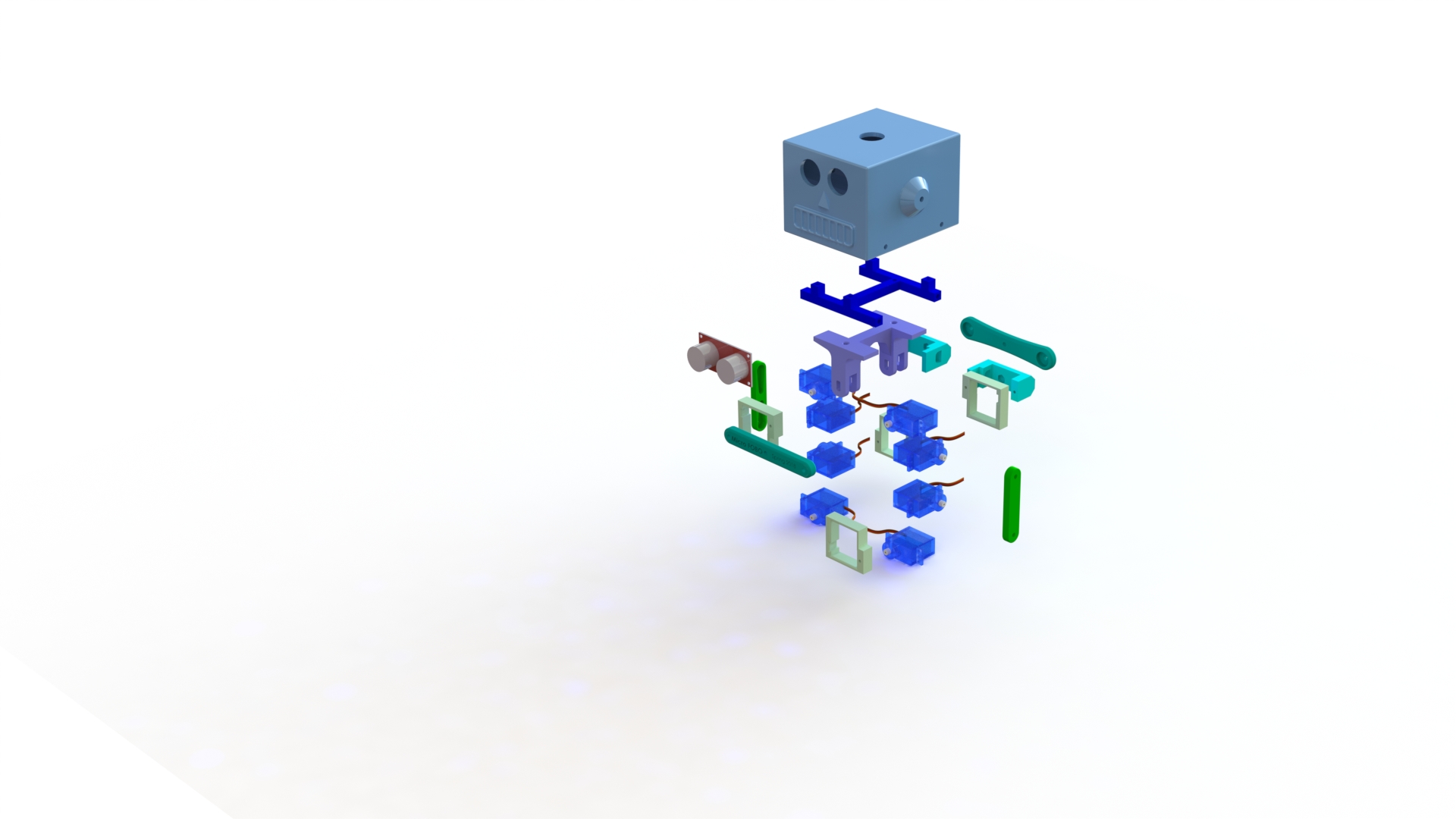
This is our first model that incorporated the Theo Jansen legs and split leg mechanism. I used a box for the body and implemented door hinges on the side that would act as the split leg mechanism that turns the legs. There are servos inside the box that are connected to these panels, and the servos would move the panel in and out to turn the legs. The DC motors are planted on the other side of the panels inside the box, and the motor is connected directly to the Theo Jansen leg. The motor rotates the leg and creates the walking motion for the robot.

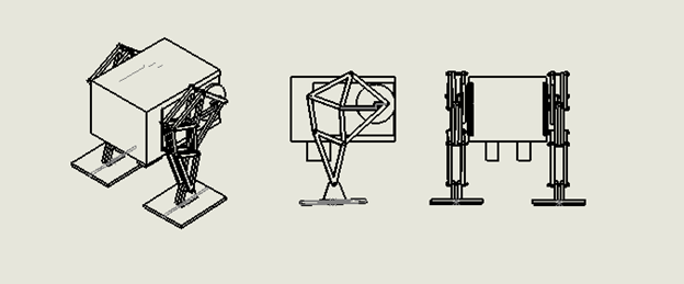
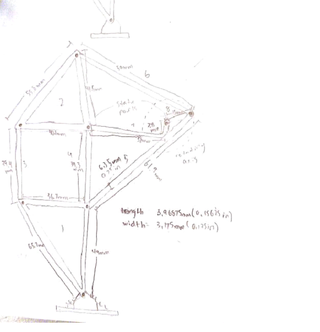
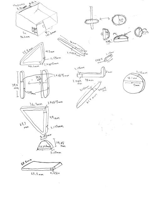
Figure 3: Side views of Preliminary Model

Issues with the model

Some issues with the model include the distance between the legs and center of mass. Because the legs are so far apart, it makes it much more difficult to balance the center of mass when the servos are turning the legs. If we had the legs closer, the weight is closer to the center instead of the sides and it will be easier to balance the robot. The box body takes too long to print and exceeds our requirement of six hours. Also, there are issues with the foot design, and how it plants itself on the ground when it is moving in circular motion. Because it is moving in a circular motion, the foot cannot be static or else it will not stay in parallel with the ground and that will cause points of contact that will conflict with the walking motion. The previous velociraptor group used springs in order to allow the foot to move in parallel with the ground, but it was not stable and made balancing the robot harder.

Conclusion

Our new design incorporates DC motors to move the legs. We will incorporate a weight shifting mechanism in the future with a servo so that we can do robot balancing during walk motion, but for now, the servos are used to turn the legs. A future modification of the design may include less distance between the legs so that we can balance it easier and a smaller mass for the body so that we can fulfill the print time requirement.

Spring 2018 AT-ST Mechanical Drawings

By: Danny Pham (Design and Manufacturing Engineer)

Verified By: Intiser Kabir (Project Manager)

Approved By: Miguel Garcia (Quality Assurance)

Introduction

For our robot to walk and turn successfully, we will be designing elements of the robot that will be able to balance itself and move smoothly. The AT-ST walker design will incorporate parts of the Velociraptor and Biped design from previous semesters. The AT-ST will also incorporate dc motors instead of servos, so we switched out from our previous Titrus III leg design. In our case, our robot designs will be using the Theo Jansen leg design and split leg function that the previous 2017 Spring velociraptor project used.


Concept Sketches

Figure 1: initial sketches and idea of Priliminary Model

Description

For the body of the AT-ST walker, for preliminary design, we will be using a box. The box will have side panels that open and close like a door. The Theo Jansen legs will be attached to the outside of the panel, and the motor will be mounted on the inside of the side panels to connect to the legs. Another set of gears and servos inside the body will move the connector to open and close the doors, which in turn will turn the leg like split leg function.

Figure 2: initial ideal measurement of our Theo Jansen Leg

Description

This is the Theo Jansen leg design. The measurements are taken from the actual Theo Jansen leg dimensions. The width that we picked for the leg is 3.175mm because it will be made of carbon fiber and that width is sturdy enough for the carbon fiber material to support the leg.

Figure 3: 2D Sketch of Theo Jansen Legs

Description

The leg is structured so that it is not just a one dimensional build of the leg. Each component is doubled so that the leg structure is wider and that will make the leg more stable. The previous velociraptor group also included springs on the feet in order for the foot to not be parallel to the ground at all times. This will help the Theo Jansen leg motion and keep it moving.

Figure 4: Measurement Parts

Description

These are the individual measurements of each connector in the legs, and other miscellaneous parts in the body.

Conclusion

These will be the basic design of the AT-ST walker robot. The measurements used for the leg design are scaled versions of the actual model and models from the previous semesters to fit our maze and robot definitions. The measurements and shapes are subject to change once we test the function of a rapid prototype of the robot design.

Spring 2018: BiPed 3D Print Time

Written By: Miguel Gonzalez (Project Manager and Manufacturing)

Approved By: Miguel Garcia (Quality Assurance)

Update: 3D Printing Time Waiver (Approved on 5/01/2018)


Introduction

In this blog post, we will cover the overall 3D print time for the complete assembly of the Mirco FOBO. The Micro FOBO’s design is based on the original FOBO which was created by Jonathan Dowdall but utilizes updated and revised components. The design of the components will not be mention in this post but can be found in our Mechanical Design blog post. This post will explore the time it takes to manufacture parts for the Micro FOBO using a 3D printer. To better calculate the amount of time, use for fabrication I have created a table listing all the parts that are needed to assemble our robot and listed the time it takes to make it. Micro FOBO uses a total of fifteen 3D printed pieces which takes seven hours and forty-eight minutes. It is important to note that our current printing time violates our customer’s program requirement of keeping the printing time under 6 hours total. Only the head of FOBO exceeds the 2-hour limit of 3D printing requirement per part. Due to this violation, we have decided to appeal this requirement with a waiver document. By getting the approval of the customer through this appeal we won’t need to make any changes to our design or 3D printing process.

Related Requirements

Level 1 Requirements:

L1-8: Micro FOBO’s part components will be 3D printed using the material carbon fiber PLA.

L1-9: Micro FOBO will not exceed a print time of 7.80 hours. Upon approval of the waiver.

Level 2 Requirements:

L2-2: Micro FOBO dimensions will need to be small enough to fit in a 4in by 4in box for maze purposes.

L2-15: Micro FOBO shall weigh no more than the allocated mass of 460g.

Fig.1 Printing Times on Simplify3D

Table Data:

The table above shows Micro FOBO’s parts listed with their own “Build Statistics” which is information about the part’s printing time, weight, and cost of materials. This information was gathered through the slicing software, Simplify3D. All parts were listed to have a layer height of 0.20mm and 25% infill when producing the printing time information.

Final Remarks

It is important to note that the printing time shown above has been completely processed via slicing software but has been verified to be correct when printing the first full prototype. All 3D printing is done through my own 3D printer but the material (Carbon Fiber PLA) bought will be processed for reimbursement. As mentioned before, we currently exceed the amount of time allocated by the customer for printing time. The main reason we cross the six-hour mark is due to the head of FOBO requiring large amounts of support material and thus requiring more time to print out. We hope that the customer accepts our printing time waiver to allow us to keep the same head design and printing process.

References

Spring 2018: Testing Design Sketches

Written By: Miguel Gonzalez (Project Manager and Manufacturing Engineer)

Approved By: Miguel Garcia (Quality Assurance)


Table of Contents

Related Requirements

Level 1 Requirements

L1-3: Micro FOBO will have 2 legs.

L1-4: Micro FOBO will be a toy robot based on the design of the FOBO by Jonathan Dowdall.

L1-8: Micro FOBO’s part components will be 3D printed using the material carbon fiber PLA.

L1-11: Micro FOBO shall be 60% or less of the overall size of Jonathan Dowdall’s FOBO

Level 2 Requirements

L2-2: Micro FOBO dimensions will need to be small enough to fit in a 4in by 4in box for maze purposes.

L2-3: Micro FOBO will use SG90 micro servos.

Customer Requirements

C-03: The robot will be designed to be a toy for people ages 8+.

C-04: In order to minimize manufacturing cost, and packaging cost the robot shall be able to be constructed from sub assemblies within 10 minutes.

Before CAD

One of the first things we did when verifying our sketches was produced a copy of the original FOBO from www.projectbiped.com this would help in determining correct aspect ratios for the creation of the Micro FOBO. Using parts from previous semesters we managed to get all the necessary components to produce the FOBO. We 3D printed the parts for FOBO and assembled it all within the first three weeks of the semester.

Fig.1 Original FOBO Source: projectbiped.com

Fig.2 Printed FOBO


By using the printed out FOBO I was able to measure the individual parts of the robot and produce a scaled down version of each part. It mainly relied on using ratios of the larger servos compared to the micro servos our group planned on using. Figure 2 is an image that was taken after the testing of the micro FOBO parts but is a good illustration of the size comparison between the original  FOBO (in blue) and the Micro FOBO (in black).

Creating the 3D Models

After creating the Initial Design Drawings on paper I made sure to 3D model the parts on Solid Works and test how the parts fitted together. Typically we can verify how the parts work together by using Solid Works Assembly and verifying the dimensions allow the parts to fit onto the micro servos and with one another. Of course, all parts first needed to be designed before we can verify part compatibility this also included designing the micro servos, ultrasonic sensor, and custom PCB. Below you will find 3D models of parts and components that were designed in Solid Works CAD.

Fig.3 3D Model of Micro Servos

Once all the parts were 3D modeled the first compatibility test on the parts was conducted by assembling all parts together using Solid Works. This process involved virtually assembling the Micro FOBO and verifying that all parts fit together properly and that all mounting holes aligned with each other.

Fig.4 Micro FOBO Exploded Assembly

Fig.5 Micro FOBO Full Assembly


Testing the 3D Models

The last thing to do was to 3D print a prototype of the Micro FOBO and verify the results obtained from the assembly. Most parts that were printed out needed no revisions. Only the servo band and servo bracket required revisions. These parts typically required revising the mounting holes for the micro servos and slightly increasing the holes where the wires fitted through. Once the changes were applied to the model the parts were 3D printed again and verified that the issues no longer remained. We tested all designed parts by assembling a full-scale working prototype as shown below.

Fig.6 Part Verification

Fig.7 Testing Servo Fitting


Fig. 8 Part Verification with Sketches

Fig.9 Assembly Process

Fig.10 Head Verification and Assembly

References

  1. www.projectbiped.com
  2. Initial Design Drawings

Spring 2018: BiPed Initial Design Sketches

By: Miguel Gonzalez (Project Manager & Manufacturing)

Approved By: Miguel Garcia (Quality Assurance)


Related Requirements

Level One Requirements

L1-3: Micro FOBO will have 2 legs.

L1-4: Micro FOBO will be a toy robot based on the design of the FOBO by Jonathan Dowdall.

Level Two Requirements

L2-3: Micro FOBO will use SG90 micro servos.

L2-14: Micro FOBO shall measure within 4.5” x 3.25” x 7.25”.

Initial Sketches and Design

Since our robot was going to be based on the original FOBO created by Jonathan Dowdall we first needed to do some observation on his design. The original FOBO measured 24cm ( 9.5″) tall and 15.25cm ( 6″) wide. Because we are creating a miniature version of this design we can measure the servo size the original FOBO had with the micro servos we plan to use. As fig.1 shows, we can measure the two different servos and calculate their perspective ratio size with one another to give us an approximation of how small we can make our robot.

Fig.1 Calculating Ratio Sizes

Various ratios were calculated from the measurements of the two servos and we discovered that our micro version of FOBO will be approximately 60% scale of the original FOBO. This is quite a significant reduction. Now that we had our ratios and measurements of the servos we could begin by sketching some of the FOBO parts and incorporate them to suit our miniaturized robot. The servo band and servo bracket were one of the first parts to be sketched and design since these parts attached the servos onto the FOBO’s leg. Measurements from the servos and the servo horns make up the dimensions of these parts. Since the micro servos were designed to be pressure fitted onto some of the parts small tolerances where only acceptable. It was made sure to only use datasheet measurements with verified dimensions from caliper measurements.

Fig.2 Sketches of Bearing Frame and Servo Wrap

Fig.3 Body Riser Sketches

Many of the initial sketches have inaccuracies in their stated dimensions, this is due to the fact that testing and fast prototyping is needed to verify that the pieces would fit together. When designing the head of the robot it became evident that simply reducing its size by 60 percent of the original FOBO will not be sufficient. The head of micro FOBO is reliant on the size of the 3DoT board and the shield that will be mounted on it. Rough estimates on the dimension of the controller board were guessed in order to begin an initial sketching of the robot’s head. Once the head had been sketched it became evident that we can do some designs on its face to better meet the robot’s requirement of looking like a toy. This meant that we could use the ultrasonic sensors to look like eyes and thus we can design a nose and mouth to finish the face features. Antennas were also sketched on the head of the robot to simulate how toy robots looked like in the 1950s.

Fig.4 Head Sketches

Fig.5 Full Body Sketch

References

  1. http://www.projectbiped.com/prototypes/fobo
  2. 1950s Robot Toys

Spring 2018 AT-ST Product Breakdown Structure (PBS)

By: Joseph Cho (Mission, Systems, and Testing)

Verified By: Initiser Kabir (Project Manager)

Approved By: Miguel Garcia (Quality Assurance)


Introduction

The product breakdown structure below visually presents the products that will be created based on the assignments. The product breakdown structure should reflect the work breakdown structure created beforehand.

Figure 1: AT-ST Product Breakdown Structure

Description

The PBS (Product Breakdown Structure) is showing the different productions by each division. E&C (Hardware) division will be making a custom PCB shield for the sensors and gyroscope. E&C (software) division will be programming codes for movement and sensory data. Manufacturing division will be prototyping models for the body and legs of AT-ST. MST division will be customizing Arxterra control panel to have suitable commands and telemetry for AT-ST.

Reference

  1. https://www.arxterra.com/fall-2017-velociraptor-preliminary-design-document/

Spring 2018 AT-ST Turning Code

By: Samuel K Yoo (Electronics & Control – Software)

Verified By: Intiser Kabit (Project Manager)

Approved By: Miguel Garcia (Quality Assurance)

Table of Contents

Introduction

The objective is to focus on the different methods of turning for the robot. The first method is timing turning which tells the robot to turn for a certain amount of time. The other is an infinite state machine which uses the outer sensors to tell the bot which state it is in. This turning sequence used for the robot has wheels, which the AT-ST does not. The concept of turning can be used for the AT-ST.  

Code

CHANGE CODE TO <code> type

Figure 1: Screenshot of code

Figure 2: Continuation of Screenshots of code

Figure 3: Last part of code screenshot

Explanation

The code, in the beginning, initializes certain variables and sets them as inputs and outputs. After this the code contains a line follower code which makes the robot follow the line. There are then the subroutines for the time turning. The subroutine near the end of the code allows the bot to make a left, right and turn around. Time turning is a method of spinning the wheels in the same rotation until it points in another direction.  Each turn must be tested to find the desired direction. The values in the code are placeholders until real values are obtained. This code however only works with motors, not servos and needs to be updated at a later date. The finite state machine code is not in the list above, however, I can explain the logic and some pseudocode.

The logic behind the finite state machine is to switch from one state to another state. These states will tell the robot it needs to continue, turn, or not until it reaches another state. If all sensors read black, it is at an intersection and will either start turning left right. Next, it would jump to the next state and see if the sensors outer sensor read the white part of the maze if so it would continue to turn until it sees all black. After that, it would proceed to move forward.

Conclusion

This whole entire blog post is to make the turning code. The time turning is in the code, however, it does not suit the AT-ST because of the difference in components. The finite state machine is not implemented yet. This post will require further updates for both the inclusion of the state machine turning and the servos.

Goliath Spring 2018 – L1 & L2 Requirements

By: Ryan Nguyen (MST Engineer)

Verified By: Ernie Trujillo (Project Manager)

Approved By: Miguel Garcia (Quality Assurance)


Table of Contents

Level 1 General Requirements

  1. The robot shall be completed by May 15.
  2. The robot that is to be designed shall be done in such a way that it is relatively inexpensive, less than $250, preferably a laser cut model or 3D printable design.
  3. Since robots are to be operating through the maze simultaneously, the design should ensure that collisions are to be avoided in all situations.
  4. When printing 3D models for the project, any prototype print shall obey the 2/2/2 rule and shall take no more than 6 hours in sum. Projects may request a waiver with justification.
  5. Robots shall utilize a version 6 3DoT boards powered by the 3.7V RCR123A battery. Projects may request a waiver with justification.
  6. The robot will be designed in such a way that there are no dangling or exposed wires. Connectors will be used between all electronic and electromechanical components. Jumper wires will not be used, ribbon cables are preferred; the gauge of wires should be consistent with the current.  
  7. Good construction techniques: all moving and rotating parts shall use bushing or bearings, hinges shall be interlocking and include a latching mechanism. No gaps shall be greater than 1 millimeter, immediate access shall be provided to all external connectors (USB, switches).
  8. The robot shall record the user’s input and be able to repeat the previous route defined by the user. The software algorithm is defined in 400D E&C lab sequence.
  9. During teaching mode, ArxRobot app via mobile devices shall be used to teach the robot to navigate the maze.
  10. During the playback mode, the ArxRobot app shall transmit live video feed and telemetry to the Arxterra control panel, including battery level.
  11. The Robot disassembly time shall be 10 minutes. Projects may request a waiver with justification. All 3Dot boards will be clear of electronics, motors will be disconnected, all sensors will be disconnected.
  12. Reassembly time shall be 10 minutes. Projects may request a waiver with justification. All teams will be allowed to use a cable tree as well as an assembly diagram as necessary. All robots will be tested after reassembly to confirm its functionality.

Goliath Level 1 Requirements

Project:

L1 – 1 The Goliath will drive on flat surfaces, such as cloth, paper, linoleum.

L1 – 2 The Goliath shall be operational for 1-hour duration.

L1 – 3 The robot shall be a scale replica of a Goliath 302 Tank. The scale factor will be 1:11.5 with a mean

          square error (MSD) over all three axis (x, y, z) of no greater than 10%.

L1 – 4 The total cost of the goliath shall be no greater than $200.

L1 – 5 The Goliath shall have easy access to charging and programming hookup.

L1 – 6 Goliath shall house a custom PCB and use control telemetry shall to navigate the maze.

Program:

L1 – 7 The Goliath should make tank noises.

L1 – 8 Goliath shall detect and avoid other robots in the maze.


Goliath Level 2 Requirements

System:

L2 – 1 The mass of the Goliath shall not exceed 400 grams. Goliath L1-3

L2 – 2 The Goliath shall be smaller than 5x4x3 inches. Goliath L1-3

L2 – 3 Goliath shall use IR range finder to detect objects. Goliath L1-7

L2 – 4 Goliath’s final version shall be printed with ABS plastic. General 3

L2 – 5 The Goliath shall be power by a single 3.7v RCR123A battery. General 6


Subsystem:

L2 – 6 Main PCB shall have two UV sensors, UV LED, Gyro, and connectors to range-finder. Goliath L1-6

L2 – 7 Arx-robot App will have different operating control modes and direction pad to control Goliath’s

          movement. Goliath L1-6

L2 – 8 Goliath shall have 4 x 10 mm cut out on back of Goliath to provide access to charging and

          programming hookup. Goliath L1-5

L2 – 9 The Goliath will not have any electrical parts mounted outside. General Level 1-7

L2 – 10 The Goliath should have a latched lid. Interlocking mechanism. General Level 1-8

L2 – 11 The Goliath shall detect objects 10 inches in front. Goliath L1-8

L2 – 12 Goliath will have all-terrain tracks. Goliath L1-1

L2 – 13 The Goliath shall have 10 gears. Goliath L1-1

L2 – 14 The Goliath shall have 2 motor(s), located in the back of the chassis. Goliath L1-1

References

  1. Goliath 2017 PDR
  2. https://docs.google.com/document/d/1cyjXSxK7dr–Xwo8d_XS3zJ5vIeamPyu2YjNbjs5Hzw/edit

Spring 2018: BiPed Ultrasonic Sensor Board & Prototype Fritzing Diagram for BiPed

By: Jorge Hernandez (Electronics & Control Engineer)

Verified By: Miguel Gonzalez (Project Manager)

Approved By: Miguel Garcia (Quality Assurance)


Table of Contents

Introduction

From the research performed, the number of ultrasonic sensors required to make a biped
robot is one sensor. We know one sensor will be used which will cause the robot to only
detect objects in a one-directional plane. According to our level 2 requirements, we are using
the ultrasonic HC-SR04 sensor to meet out level two requirements:
Shall be able to see other robots to avoid a collision. The robot will stop completely and wait for
a command. (Ultrasonic sensor). This expands farther:
1. If the sensors are too far from an object, the robot will move forward.
2. If the sensors are too close to an object, the robot should move backward.
3. If the sensors are within the range of an object, the robot will not move.

Types of Ultrasonic sensors

Ultrasonic sensors have a range of 2-450cm (0.78-177in) which will be suitable to track the
other robots from 20 inches away. The way ultrasonic sensors operate is through emitting
sound waves and detecting the sound reflected back from the object. From the reflected
sound, the sensor can provide a measurement of how far an object is away from it. The pros of
ultrasonic sensors are that they can detect objects from farther distances and they can detect
small objects accurately. Also, they can operate in harsh conditions such as dirt. However, they
have slower response times than other sensors, their measurements can be distorted by loud
noises, and surfaces that absorb sound can deter their measurements. The dual cylinder
HC-SR04 is powered up through a 5V source, which will be suitable for our application because
we are using a 5V source coming through the I2C pins of the 3DoT board. The single cylinder
MaxSonar EZ1 Sensor can be powered through a 3V source, which will not be compatible with
our project. This makes the HC-SR04 Sensor the ideal ultrasonic sensor to use in our application.

Prototype Fritzing Diagram for BiPed:

The Fritzing application allows a physical breadboard design to be created digitally. By designing
a digital version, the beginning PCB designs can begin. One difficulty with using the free
software is that the library does not have all the parts needed for many designs. Using Google,
many of the parts required were found with Github.
Here are links to the Fritzing libraries for FOBO:
(If using the Adafruit Servo Driver)
(For the Bluetooth Module HC-06 and Accelerometer/Gyroscope MPU-6050)

Fig.1 Electronic Fritzing Diagram


There was nothing to change at all as we are using the FOBO’s same hardware build. We decided
to go with 2 Lithium Ion batteries, 12 servos, and ultrasonic as well. The color sensor is being
discussed since we know Spiderbot wants to use UV sensors but will be added to fritz diagram
once we know the final maze descriptions.

References

Updated Here: Blog Post