
By: Brandon Perez
Approved by: Ijya Karki (Project Manager)
Table of Contents
A final update of the requirements with completed values is provided below. The reason for preparing quantitative requirements is to ensure that during the validation and verification tests, we have more testable criteria.
The Biped shall statement…
-Date has been determined for the semester duration and scheduling for class finals.
-Budget has been determined by the customer.
-These requirements have been set by the customer.
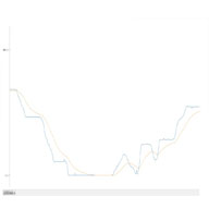
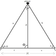
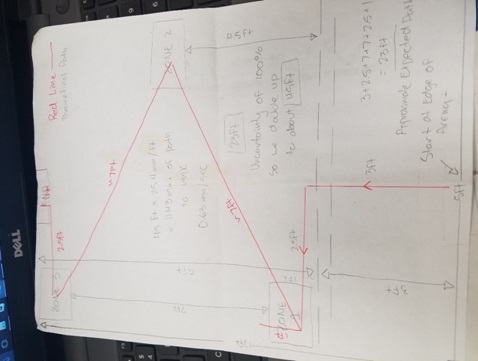
-Based on the expected arena size, we have estimated an expected worst case scenario path of 45ft during the entire game duration. The red path on the picture below indicates an expected path for our Biped to travel which totals up to 23ft. We decided to double up the expected distance traveled due to a 100% uncertainty. With a 45ft distance to travel as a worst case scenario in a duration of an hour, we have set our minimum speed requirement to be 0.32 mm/sec because 45ft*(25.4mm/inch)*(12inches/ft)/(3600secs) = 0.32 mm/sec.
-The servos that have been provided to us have a 180-degree range of motion. We can restrict this range of motion even less, but we have decided to work with this full range because we will be able to turn 180 degrees from any side, which means our robot has the capability of turning directly around no matter what foot is placed on the ground.
We are to control the Biped in RC mode during the game as it is a requirement by the customer. Since the longest dimension of the arena is 12ft, we would operate the Biped at 12ft away in the case we were right at the edge of the arena with the mobile device on the floor.
We were provided the servos to our group by the customer at no cost, therefore we conducted an experiment to see how much weight the servo could handle on top of its shaft’s axis while still being able to operate properly. The reason behind this type of load test instead of the traditional motor torque test was because these servos are being placed underneath the legs of the Biped to act as ankles to help turn the Biped. It was found the servos would still be able to turn loads up to approximately 750 grams which had defined our mass limit for our Biped.
One of the requirements for the Biped to participate in the end-of-semester game, “Save the Human” is that the Biped must be able to detect “power-up” zones upon which the Biped can have vulnerability against the opponents. The power-up zones will be indicated by red, blue, and green color pads.
The Game Committee, which is the organization of Project managers for the groups participating in “Save the Human”, have decided that the game duration will possibly take up to an hour.
The angle climb requirement along with the maximum angle deviations have been set by the Game Committee. This requirement has been dropped from a “shall” statement to a “should” due to lack of progress with achieving walking.
The height climb requirement has been a traditional requirement following from previous generations of Bipeds for capability of climbing over small heights. The max height deviation of 0.5cm has been set by the game committee.
The Biped shall statement…
The DC Motor we are to use must be rated at 5V to operate effectively with the 5V supply from the 3Dot’s DC Motor driver. A torque of 9.75×10^-3 ft*lbs has been determined because the Biped’s legs weigh 70 grams = 0.15 lbs each, and are cranked at 1 cm = 0.0325 ft from the DC motors axis. We used the formula T=F*d to obtain the minimum torque required of our motors.
The servos that will be used to control the Biped’s arms must be able to move the combined mass of the 3D printed arms over to both the left and right side of the Biped. They must have an operating voltage of 5V or greater because they are being powered through the external power source which will be supplying 5V with the use of an LDO regulator. The servos must be capable.
The rate of the rotary encoder has been chosen to be a ratio of 40:1 with respect to the motor speed to ensure an optimum resolution of the motor shaft position during operation that way the Biped can maintain stability when walking.
An RGB LED has been chosen to be an indicator for the user to know that the color sensor has detected the color of the color pads. When the Biped picks up the color of the power-up zone color pads using the color sensor, the resulting color shall be displayed on the RGB LED for a minute duration.
An IMU has been chosen as our sensor or chose for detecting when the Biped is walking on inclines or declines of max angle deviations of (+/-)6.5 degrees which is the value that has been set by The Game Committee.
It was found that the amount of current drawn during our most energy expensive operation, walking, was 560mA. We decided to use this basis as our average current drawn from the battery. If our system must operate for a whole hour, then our battery must provide at least 560mAh because 560mA drawn for the course of an hour will have resulted in 560mAh of total energy consumed.
This is the final update to the requirements that will be used to come up with the verification and validation matrix. Once the matrix is completed, Biped can begin conducting tests as proof of our accomplishments.

By: Hector Martinez
Approved By: Ijya Karki (Project Manager)
Table of Contents
Requirement
The Biped design correlates to all level 1 and level 2 requirements because the body will house all components.
This design document reviews the design process for Biped starting at week 9 of the semester. Up until week 9, the manufacturing engineer for Biped was Ijya Karki and I was co-engineer for manufacturing of Prosthetic Arm. Having done my research on prosthetics and robotic arms, I had zero knowledge of biped robotics. With two weeks until CDR, I had a steep learning curve. In order to be an effective addition to Biped, I had to understand the current design, model it on SolidWorks, and build a prototype. There was no time for me to research biped technology or come up with a new design so we had to move forward with the group’s current design.
The Biped design at week 9 featured a weight shifting body, dual dc motor gearbox, shaft encoders, and servos. Weight shifting would be controlled by the servos, one servo would shift weight left and right to aid in walking while the other servo would shift weight front and back to assist with incline walking. Shaft encoders would help track the position of each foot which would aid in coding. Everything would be housed in a multi layered body. This current design was under review by the current group and there were changes they wanted to make, I was asked to review the design and make changes necessary to ensure walking. I was also tasked with developing a turning mechanism because the current design did not have a way to turn.
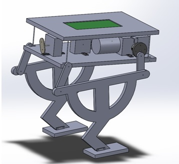
Fig. 1 – Design of the Biped at week 9 of the semester.
While simulating on SolidWorks, I discovered the walking mechanism was unstable and a more robust system was necessary. Based on the above design, the group wanted two motors that powered the legs connected at the front and the back of the legs, opposed to one at the front, we believed this would solve the stability issues while walking. I came up with the idea of adding servos at the bottom of the feet to assist with turning. Adding servos to the bottom of the feet would create ankles, we would then attach new feet to the servo to complete a turn.
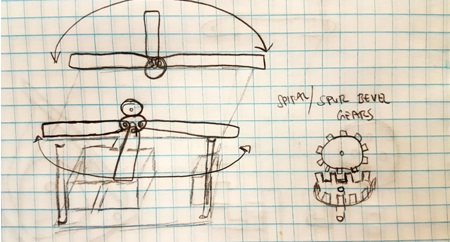
Fig. 2 – Preliminary drawing of how arms could be used to balance Biped.
Before I start modeling on SolidWorks I always put ideas on paper, by doing this, I can start to think about what aspects of my ideas are feasible. For example, figure 2 is a drawing of an initial idea I had for arms that could be rotated forward or backwards with servos to help when walking on inclines. Seeing it on paper, I realized that this design would not help with level waking because there wasn’t a way to extend the arms out to the side to shift center of mass left or right. By putting my ideas on paper first, I was able to quickly realize that this idea was not useful for Biped. Had I decided to simulate on SolidWorks only, I would have spent considerable time designing before coming to the same conclusion.

Fig. 3 – Ver. 2 of Biped design, featuring a servo at the ankle that will assist with turning.
The group believed that instead of having a body capable of shifting weight, a simpler approach was to have weighted arms capable of rotating 180 degrees on the horizontal plane. This would accomplish level walking as well as walking at an incline. Figure 3 features the servo housed in the leg with a foot attached with a servo gear. While the Biped is mid step, it has to balance on one foot, if the servo is turned in this position the whole Biped can turn and complete the step in a new direction.

Fig. 4 – Ver. 2 of Biped, featuring two motors to power the legs and the servos inside the body to power each of the arms.
By rotating the arms forward or back, the Biped would be able to shift its weight forward or back while walking on inclines. While taking a step on level ground, one of the arms would extend out while the other arm is rotated forward. This will shift the center of mass of the biped to one of the feet so the free leg can take a step. Figure 4 features the two servos inside the body which would control each arm. Below the body are the two motors that will be used to control the legs. One motor is connected at the front link of the leg while the other motor is connected to the rear link. The legs would have to be 180 degrees out of phase with each other to produce walking.
One week before CDR, the customer was asked to review the progress of the current design and to our surprise he was not pleased with any part of it. The customer had concerns that the feet were too far apart and weight shifting would not be accomplished. He liked the idea of having arms to shift weight, but did not like that the arms were extended out at all times. Apparently there was some miscommunication as to the number of motors the customer wanted to use for walking, he wanted the Biped to accomplish walking using only one motor. The only thing the customer liked about version 2 was the servos at the ankle to accomplish turning.
With a clearer vision of what the customer wanted, I needed a crash course on robotic walking. I sought the help of Aaron Choi the manufacturing engineer for Velociraptor and he pointed me in the direction of the Theo Jansen Biped (TJB) toy. The TJB featured a single crank shaft to produce walking and ball bearings which acted as weights to shift weight while walking.

Fig. 5 – Theo Jansen Biped toy that would become the inspiration for the final Biped design.
By incorporating a single shaft to produce walking, we would be able to use a single motor. The customer insisted on using arms to control weight shifting, therefore, we did not look into incorporating ball bearings as a mechanism in version 3 of our design. At this point, I was extremely overwhelmed and I was seriously questioning my new found abilities on SolidWorks. Luckily, Aaron had 8 weeks of research on Theo Jansen walking technology and helped me, a lot. With his help, I was able to produce version 3 of Biped.
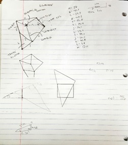

Fig. 6 – Preliminary sketch/design of Ver. 3 of Biped, featuring Theo Jansen linkages and a single motor.
For version 3 of Biped I decided to get really creative in the way I would incorporate the servo into the Theo Jansen linkages. As can be seen above, I decided to house the servo in between the bottom triangle of the Theo Jansen mechanism. I believed that adding a servo to the bottom of the triangle would cause Biped to be too tall and possibly unstable. Brandon Perez, our mission systems and test (MST) engineer, provided me with a motor that featured a single shaft which extruded from both sides of the motor. I could use this motor to attach the legs to the shaft at 180 degrees out of phase to produce walking. Additionally, the width of the motor and single shaft gave the Biped a total width of 5cm, versus 9cm from previous versions.
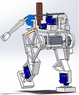
Fig. 7 – Ver. 3 of Biped. Additional features include servo controlled arms that hang to the side, TJB legs, servo controlled weight at the top to control incline walking.
I continued designing taking into consideration our requirements. One requirement was to have color sensors that would be able to sense color pads on the floor. The figure above doesn’t show the sensor housing, but the reason for the boxy feet is because the sensors would be housed under the feet. We concluded that the best place for the color sensor would be as close to the floor since that’s where the color pads would be located. The figure below shows how these feet were designed as well as how the servos would attach to the feet.
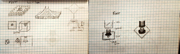
Fig. 8 – Design sketches of color sensor housing as well as servo/foot mate.
For CDR, we featured a Biped which we expected to look much like the final product. I added weights to the arms and top rear servo to simulate weight shifting for level walking and walking on inclines. The motor, servos, PCB, and 3Dot were all at their final locations. The faint outline of a body can be seen in the figure below. We were very pleased with this latest design and were confident the customer would be as well.

Fig. 9 – Design presented at CDR featuring attached weights, PCB, and simulated walking.
Unexpectedly, we were received a lot of criticism for our design. Once again, the customer complained about the width of the feet. The customer raised concerns that the Biped was too wide and would like the legs to be much closer together. The customer did like how the arms could move, but did not like how the design was implemented. The customer also liked the body design but did not like the body length, he thought the body was too long and would prefer something shorter. The criticism only grew when we presented our prototype because the prototype only validated the concerns of the customer.
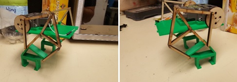
Fig. 10 – First prototype presented at CDR, the goal was to demonstrate static walking only.
The customer was not at all happy with our first prototype and gave us another week to present a second prototype. During the initial tests of this first prototype, we realized that the customer concerns were in fact right, the width of the Biped was too wide to be able to shift weight. We decided to scrap this design and work on something narrower. Figure 4 features the TJB toy with very narrow legs, the linkage design also incorporates weight shifting. Once again, I was under the gun to produce a new design in less than a week. Luckily we had in our possession, a TJB toy, and I was able to make all the measurements to create a design.

Fig. 11 – Initial drawings of TJB crankshaft, lobe design, and spacing.
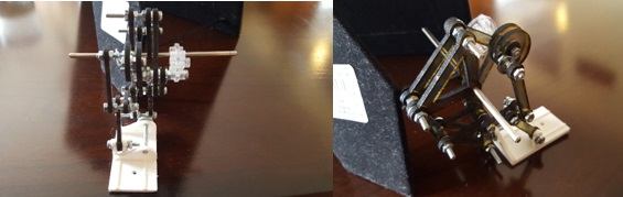
Fig. 12 – Leg design for Version 4/prototype 2 based on TJB toy.
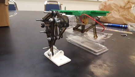
Fig. 13 – Incomplete prototype 2 with TJB toy inspired legs.
For version 4 I decided to copy the TJB toy, literally. I measured all the linkages, created them on SolidWorks, and laser cut them on acrylic. Laser cutting turned out to be considerably faster than 3D printing and was ideal for prototyping. Although prototype 2 was still somewhat wide it was a start in the right direction because the Biped actually demonstrated balancing and something that resembled walking. To fix the width issue, we needed to source a shorter motor shaft. The current shaft was 6cm and we were able to find one that was 3cm. This new shorter shaft would allow the Biped legs to be closer together. We also had issues with the gear that was provided with the motor, because Theo Jansen linkages are specific dimensions, we needed to scale our linkages to match the size of that motor gear. We realized after the prototype was built and during prototype 2 demonstration the motor would stall because the gear would hit the leg linkages. Additionally, the servo in the ankle had to be scraped because the TJB toy has a very specific foot linkages that help shift weight, the servo between these linkages obstructed the motion necessary to shift weight.
With the issues of version 4 resolved, I was able to move onto the body design. After doing extensive work with laser cutting, I figured it would be much faster to laser cut a body rather than 3D print. By laser cutting joints into the body pieces, I would be able to fit these together with little effort.
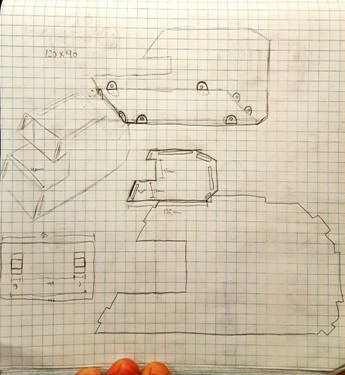
Fig. 14 – Sketches of what the body could look like. Featured are notches for easy assembly.
Based on CDR feedback, we knew the customer liked the body design which was inspired by the Star Wars ATST walker. We were not able to design arms that extended from the side of the Biped, the need for a narrow body restricted the amount of space available for additional servos. Instead I decided to house our external battery on a tray being held out by “arms”. These arms are laser cut on acrylic and the battery tray is screwed on to them.
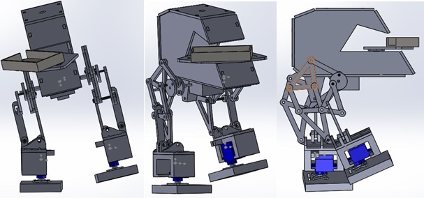
Fig. 15 – Final SolidWorks design of Biped featuring TJB legs, servo at the ankles, ATST body, and arms holding a battery tray.
Manufacturing went right up to the day of the final. Along with Alan Valles from E&C, we worked through the night to produce a walking Biped. While Alan uploaded and tested code, I routed, soldered, and managed wires. During the final presentation we played in Save the Human game in which Velociraptor Bipeds from other groups were to attack our human biped. Unfortunately, our Biped did not perform as expected. We did not have enough time to test the walking code with the balance code to produce stable walking.

Fig. 16 – Final Biped project as presented on the day of the final.
We were able to test the turning code which did produce turning. I believe if we had managed our time better we would have definitely produced a walking Biped.

Fig. 17 – Final design balancing on one foot to produce turning.
The design of this project was a long and grueling endeavor. Looking back, there are some things I would do differently. First, I would make sure to have clear expectations from the customer. When the customer is unsure of what he wants, the manufacturing engineer is expected to come up with a design that will wow the customer. This is a lose-lose situation because if such a design is reached then you are now on the hook for delivering every aspect of that design, and designs that wow are usually very intricate and complex. If such a design is not reached, then the customer is able to reject all designs, wasting value time in the process. This is even more important in a case like mine, where I had 8 weeks to do 16 weeks’ worth of work. Secondly, don’t allow others to influence your design unless you want them to. By allowing other people to influence your design you lose track of the wants of the customer. This doesn’t mean you shouldn’t seek for help, by getting someone else’s input you are able to attack a challenge in a different way. Although this was a tough project, it was very rewarding. Our leg design was by far the most complicated design out of all biped projects. The legs actually moved in a motion very similar to the TJB toy and when placed on a surface to walk, the Biped was able to walk with some human help for balance. If this group was together from the beginning of the semester, Biped would have walked and turned successfully on the day of the final.
[1] Solidworks

By: Hector Martinez (Manufacturing Engineer)
Approved by: Ijya Karki (Project Manager)
Table of Contents
Requirement
“Shall be able to walk a minimum speed of 0.32 mm/sec.”
After CDR, we discovered that our foot design was inhibiting the weight shifting that the Theo Jansen Biped (TJB) toy provides. After careful inspection, it was noted that a simple design oversight resulted in a failed CDR demonstration.
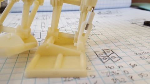
Fig. 1 – TJB toy foot with weight shifted on left foot.
The image above shows the TJB toy with its weight shifted to the left foot. Notice the link on the right with the metal cylinder, this ankle link is what causes the TJB to lean to the left and shift its weight. In this position, the right foot is able to take a step. Also notice that the ankle link is not perpendicular to the foot, instead, the angle between the ankle link and foot is necessary to allow the biped to lean. Without this clearance the biped would not be able to shift its weight and take a step.
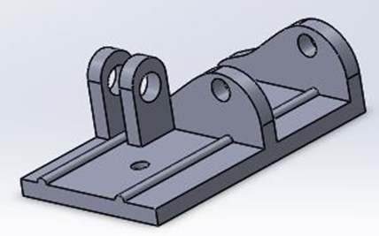
Fig. 2 – CDR foot with changed orientation of mounting bracket for ankle link.
While designing our biped, I ran into an issue which I believed to have a simple solution. The links for our TJB inspired legs are being laser cut, all the links are oriented the same direction except the ankle link. I decided to change the orientation of the ankle link to match the rest of the links because this would make laser cutting easier. I failed to realize that by changing the orientation of the ankle link I also changed the orientation of the pivot angle.
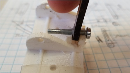
Fig. 3 – Close-up of 3D printed foot for CDR.
Notice in the picture above that the pivot angle of the ankle link is now parallel to the foot and not perpendicular as shown in figure 1. This change caused the mounting bracket to collide with the ankle link, restricting the angle necessary to make the biped lean. There was not enough time to 3D print a new foot with the proper mounting bracket orientation, thus, a quick solution was to break the top of the mounting brackets and super glue a machine screw to hold the ankle link in place. This was by no means an ideal solution and in order to make the foot work properly and redesign is necessary.
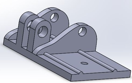
Fig. 4 – Redesigned foot which will be used on final product.
In order to make the foot work properly the orientation of the mounting bracket for the ankle link had to be changed to match that of the TJB toy. Additionally, the ankle link will have to be 3D printed to accommodate the orientation of the mounting bracket as well as the orientation of the rest of the leg links, which are offset by 90 degrees.
[1] http://www.rubberbug.com/walking.htm
[1] Solidworks

By: Hector Martinez (Manufacturing Engineer)
Approved by: Ijya Karki (Project Manager)
Table of Contents
Requirement
“Shall be able to turn up to 180 degrees on each of its sides.”
In the COM Blog Post , I discussed the leg design inspired by the Theo Jansen Biped (TJB) which uses cleverly designed linkages and shafts to shift center of mass (COM) and facilitate walking. One of our requirements is that the biped is able to turn but the TJB does not allow for turning, to overcome this issue, we are adding servos to the bottom of the TJB foot which will allow our biped to turn. In order to attach a servo to the TJB foot, I designed a custom servo housing that will act as an ankle.
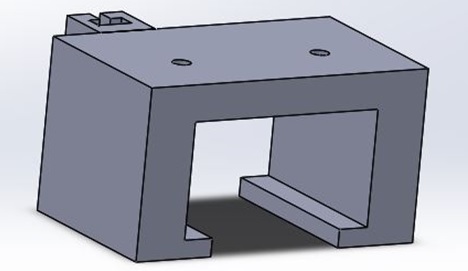
Fig. 1 – Custom servo housing that will screw directly to the TJB foot.
Once the servo is mounted, a new custom foot will be attached to the servo that will act as our new foot. This new foot will also serve as a housing for our color sensor which will go on the bottom of the foot. This color sensor is due to requirement that we must detect color pads that will be scattered on the playing field. In order to attach a new foot to the servo, a servo horn will be used that will be screwed to the foot.

Fig. 2 – TJB foot with ankle (servo housing), servo, and new foot attached.
One concern for the ankle and the reason for this blog post is the structural integrity of the ankle while the weight of the biped rests on it. When the biped takes a step, all the weight of the biped will rest on the housing and we are worried that the ankle may fracture or break. One of our requirements is that the biped should weigh no more than 750 grams. An easy and efficient way to test the ankle at this weight is to use SolidWorks. By simulating on SolidWorks we can get a good idea of the type of stress the ankle will handle. In order to perform a proper stress test, a material, load, load direction and fixture must be set on the part.
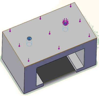
Fig. 3 – Fixtures and load direction specified on the ankle.
The image above shows the direction of the load (purper arrows). Obvisously, the weight of the biped will only cause a vertical load on the ankle, which is set to our maximum possible weight of 750 grams. The material specified is ABS plastic. A fixture is specified at places that cannot or should not move, in the case of the ankle, fixtures are set at the mounting holes to the foot (blue arrows). When the simulation is run, these fixtures will act as rigid bodies which may be subject to break or fracture.
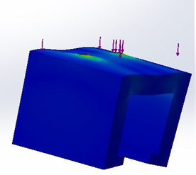
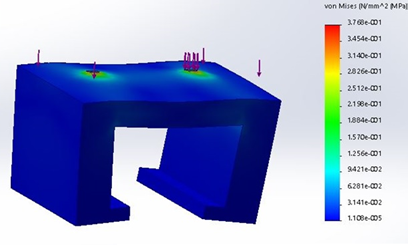
Fig. 4 – Different angles of stress analysis of ankle.
The image above shows the results of the stress analysis. The results show where and how a part may fail. The blue color indicates the ankle undergoing limited stress while red indicates heavy stress and possible failure. In the case of the ankle, there is more stress at the fixture points, but based on the color scale, the ankle is able to support this load. The simulation also shows how the ankle may warp due to the load, but this does not mean this is how the ankle will warp. Additionally, the simulation assumes that the inside of the ankle is empty. Obviously with a servo sitting inside the ankle, this kind of warping will not be possible. Based on the results of the simulation we are confident that this ankle will be able to support the maximum allowed weight of 750 grams.
[1] https://www.arxterra.com/fall-biped-2016-shifting-center-of-mass-to-achieve-walking/

By: Hector Martinez (Manufacturing Engineer)
Approved by: Ijya Karki (Project Manager)
Requirement
“Shall be able to walk a minimum speed of 0.32 mm/sec.”
A proper biped design must implement a weight shifting mechanism that allows for walking. This is because walking requires the weight of the object to be shifted to one foot so the free foot can be swung forward and repeat the process(1). The group responsible for the Velociraptor found a Theo Jansen inspired biped toy which implements a unique walking mechanism that integrates a swinging leg with a weight shifting ankle.

Fig. 1 – Packaging of Theo Jansen inspired biped, one propeller and ball bearings create walking.
The biped toy uses on motor, ball bearings, and a cleverly designed shaft to control both weight shifting and walking. We believe we can benefit from this design because one of our requirements states that our walking must be done with one motor. Other bipeds have implemented walking and weight shifting with two different mechanisms, some of the mechanisms to shift weight includes motorized hips, motorized knees, or weighted motorized arms, but these designs require multiple motors and servos. The simplicity of the Theo Jansen Biped (TJB) allows us to kill two birds with one stone.
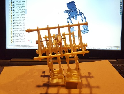
Fig. 2 – Assembled biped toy with fan removed, shaft and links provide mechanism to walk/shift weight.
The design that we presented for CDR implemented Theo Jansen legs and used weighted motorized arms to shift weight. Through simulation on SolidWorks, we discovered that the width of our feet required an absurd amount of weight (1.5 kg) at the arms to shift the Center of Mass (COM) to allow for walking. It was after CDR that we realized that two things had to change with our design: 1) our legs needed to be much closer together, like the picture above, and 2) the biped needed something more than arms to assist with weight shifting.

Fig. 3 – CDR design. Checkered circle shows where COM is located when arm is extended.
After realizing that the TJB toy implements weight shifting and walking in one mechanism, we decided to implement it to our design. Our design features a scaled version of the TJB along with “arms” which hold a battery tray. This battery tray is attached to a servo which will turn left and right on the horizontal plane, this will help us mimic the ball bearings the TJB uses to assist with weight shifting.
Conclusion
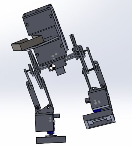
Fig. 4 – Final design. Linkages and battery tray allow the COM to be centered over the foot.
Additionally, the smaller gearbox allowed us to shorten the width of our chassis from 60 mm to 40 mm which directly shortened the width of our feet. As the picture above shows, the linkages allow the biped to use its feet as anchors, with a proper motor shaft design, these allow the entire biped to lean. Thus, this allows its COM to shift over the foot and allows the other foot to take a step. By turning the arms and battery tray, we mimic the ball bearings the TJB uses to allow for extra stability while taking a step.