Spring 2016 Velociraptor: Material Trade-Off-Study Update
Requirements needed to fulfill:
- Project Level 1 Requirement:
- According to the given course that the robot is to complete, the Velociraptor shall travel on multiple surfaces. Refer to course analysis for more detail.
- The Velociraptor shall be able to statically walk on all surfaces of the course
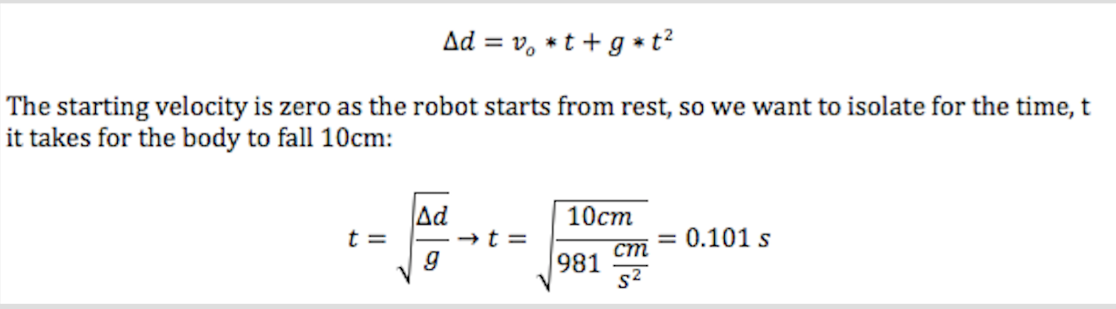
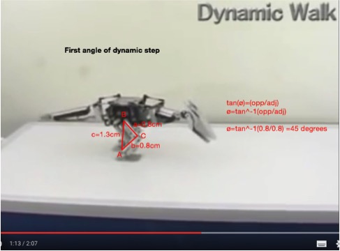
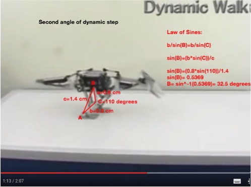
- The Velociraptor shall be able to dynamically walk on flat surfaces of the course.
- The Robot shall statically travel up a 6.5-degree incline according to the course analysis
- Project Level 2 Requirement:
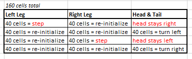
6. To maintain balance while performing static walking, a head and tail shall be implemented to the chassis of the Velociraptor to even out the shifted weight when standing on one leg and thus meet the Project Level 1, requirement
8. In order for the Velociraptor to travel on two different surfaces, the material that will be placed on the feet shall have a coefficient of friction of more than 1.0 in accordance to the Course Analysis as to refrain from slipping, and thus meet Project Level 1, requirement 3.
Actual experiments will be done to verify the feasibility of the design using our 2nd prototype.
Experiments:
- Material Trade – Off- Study:
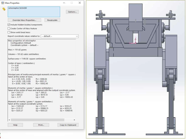
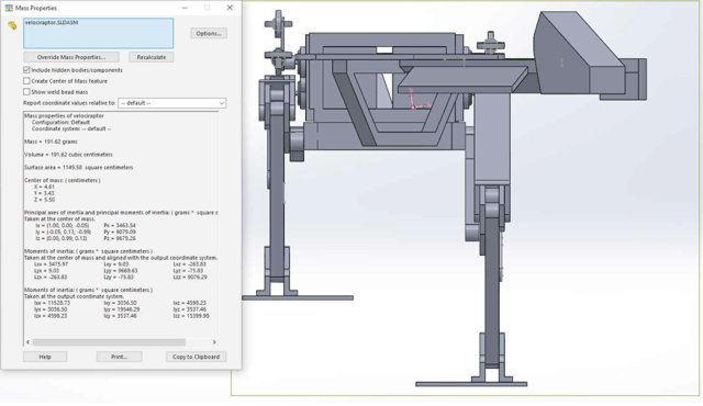
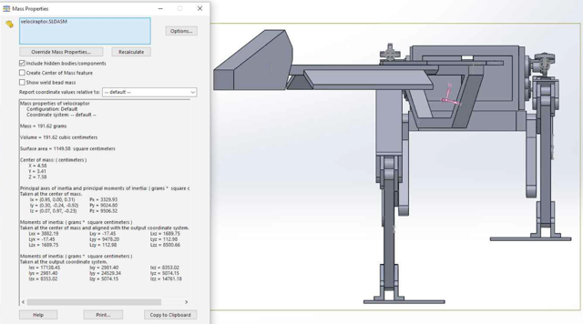
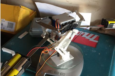
a) First Experiment included the feasibility of using 3D filament Polylatic Acid (PLA) for our final robot. When we started building our 2nd prototype, including the head and tail, we’ve decided to distribute the weight of the body by placing the batteries toward the head and tail to put less strain on the servos. By using this design, we will be able to minimize weight of the chassis of the robot and use the weight of the head and tail to shift center of mass.
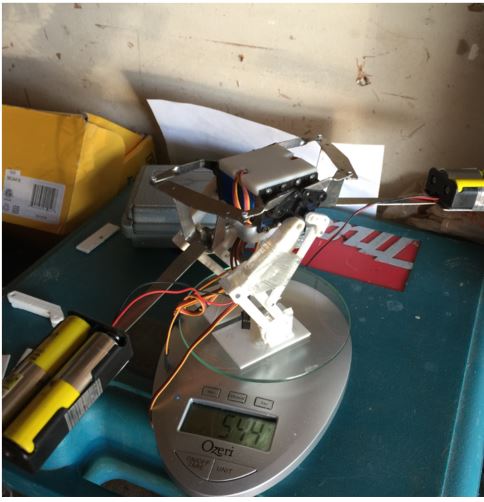
But putting more weight toward the head and tail, caused the bottom piece of the body that connects the head to start cracking which made us do a material trade-off-study to determine the right material for our robot.
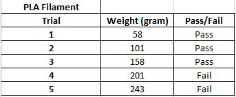
Trial using PLA filament
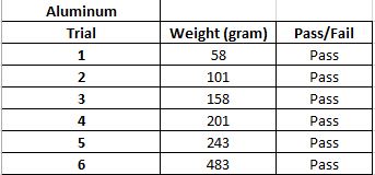
Trial using Aluminum
The printing the bottom piece using the 3D filament weighed 13 grams compared to Aluminum piece which weighed 19 grams. This not only shows the feasibility of using Aluminum for our bottom piece to maximize the weight on the head and tail, verifying project level 2 requirement 6 to implement head and tail on the chassis to shift the center of mass to balance when it’s performing static walking.
b) The second experiment was conducted in order to verify the 3D filament PLA is feasible perform static and dynamic walking on various surfaces without slipping.
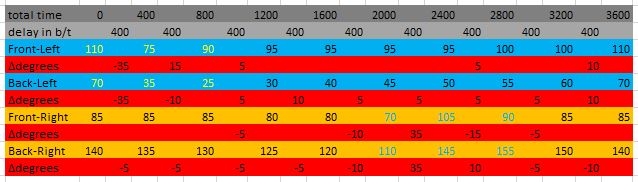
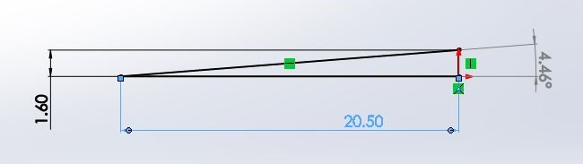
Level 1 requirement 6 states the robot should perform static walking on a 6.5 degree incline, so we’ve created inclines using various degrees to determine if the robot was able to balance and refrain from slipping at a minimum of 6.5 degrees. For our experiment, we started off by creating a slope from 4.5 degrees to 13.7 degrees and tested to determine the degree the robot starts slipping. In order to create a similar static friction of the course, we have implemented a carpet on the incline. For experimental measurement, we’ve used a protractor to measure the angle of the slope, and for the theoretical measurement, we’ve used the length and height to calculate the slope:
Both feet on Ground:
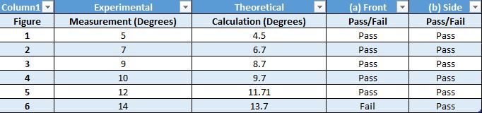
The chart above shows the acceptability of the 3D model, when we assembled the robot, it was able to stand with both foot on the ground up to 15.7 degrees without slipping or falling.
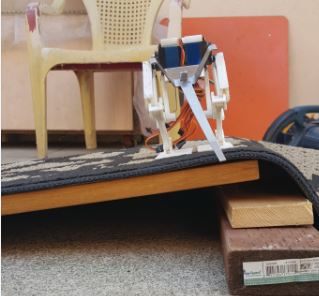
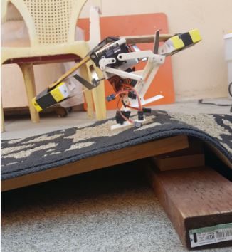
Placed sideways on a 8.7 degrees incline, successfully balancing and refraining from slipping.
Robot placed on a 8.7 degrees incline without slipping or falling.
One foot on Ground:
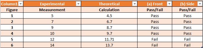
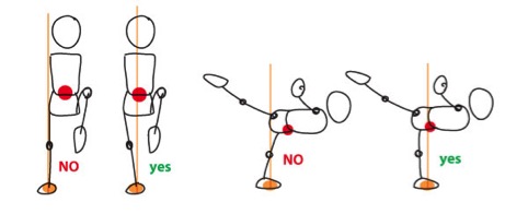
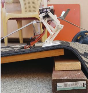
When the robot is performing static walk on incline, we’ve tested if it was able to balance on one foot without falling or slipping. As shown above, the experiment showed the robot was able to balance on one foot up to 9.7 degrees incline.
By shifting the weight of head and tail toward the shifting leg, the robot is able to stand on one foot as if it’s performing static walk. It’s able to stand on a 8.7 degrees incline without slipping nor falling.
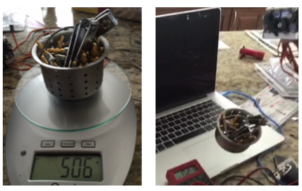
Conclusion
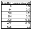
Using a thicker material for the bottom piece will not only increase printing time, but also create less space for our components to fit. But by using Aluminum for the bottom piece of the body to hold the head and tail, not only will it be able to hold up to 483 grams but also we will be able to keep enough space in the middle to mount the PCB. The test to verify the material used to refrain the robot from slipping have been successful. The robot was able to stand on both feet and on one foot up to 9.7 degrees without slipping. When the robot has to stand on an incline of more than 10 degrees, we will have to reconfigure the robot’s ideal standing position to slightly lean forward in order to make sure the center of mass stays in the middle of the robot’s body.