Spring 2017 Velociraptor: Final Project Summary
Table of Contents
Author
By: Jesus Enriquez (Project Manager)
Spring 2017 Velociraptor Project Team:
Jesus Enriquez (Project Manager)
Oscar Ramirez (Mission, Systems, & Test)
Mohammar Mairena (Electronics & Control)
Andrea Lamore (Manufacturing)
Executive Summary
Program Objective
The Objective of the EE 400D Velociraptor Robot is to produce a robot that emulates the body of a “Velociraptor”. The robot will compete in a custom game of “Pac-man”. The finished product must meet the following Program and Project Requirements:
- Total production cost must not exceed $200.00 as agreed upon between the project team and the College of Engineering
- The load of the Velociraptor shall be primarily driven by DC motors
- The Velociraptor will be controlled through the Arxterra App (Android or iPhone) using Bluetooth
- The Velociraptor shall use the 3DoT board and custom PCB to carry out robotic controls to achieve mission success as defined in the Mission Profile
- The Velociraptor shall perform a static walk as it navigates the custom maze
Mission Profile
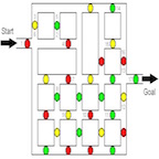
The Velociraptor Robot shall compete in a “Pac-Man” style game against the Biped Robot during the EE 400D Final on May 15th, 2017 as described below:
- The game will involve both robots starting on opposite ends of the maze in which the Velociraptor will begin the game as the “Ghost” , whereas the Biped will act as “Pac-Man.”
- The Velociraptor shall attempt to collect as many dots as possible while navigating the maze utilizing either a static or dynamic walk.
- Control of the Velociraptor will use the Arxterra Control Panel.
- Video support will be provided by the Spiderbot from an aerial view.
- The Velociraptor shall use the 3DoT board and a Custom PCB to carry out the robotic controls in order to achieve Mission Success
Project Features
- Static Walk
- The Velociraptor shall be able to perform a static walk in order to navigate the custom EE 400D maze.
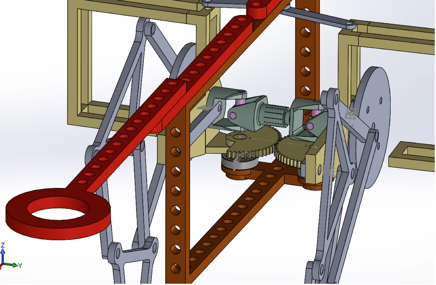
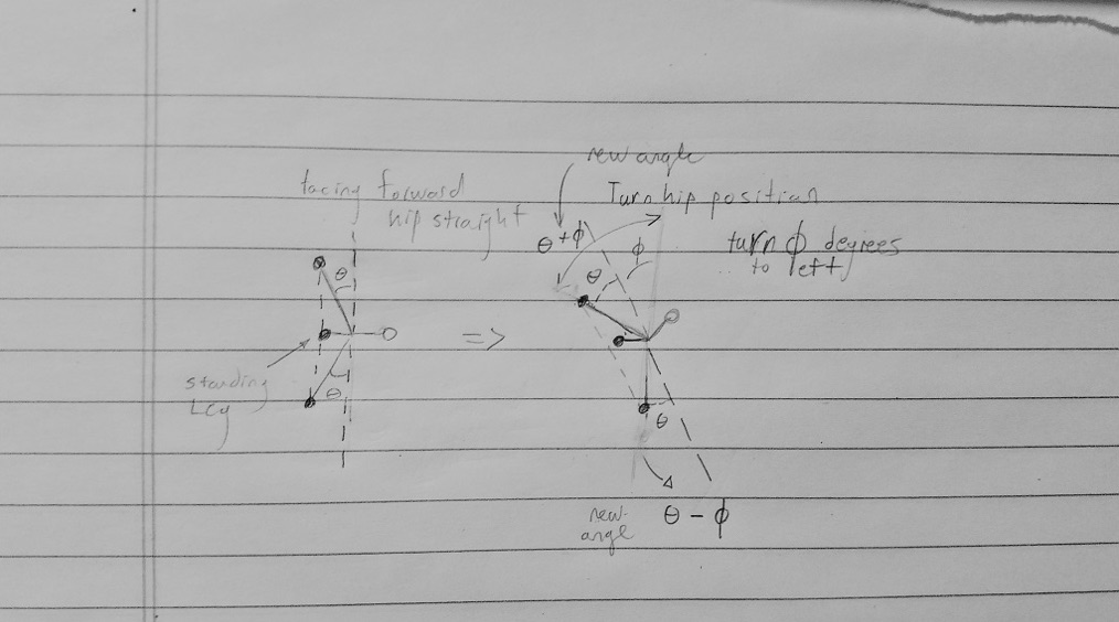
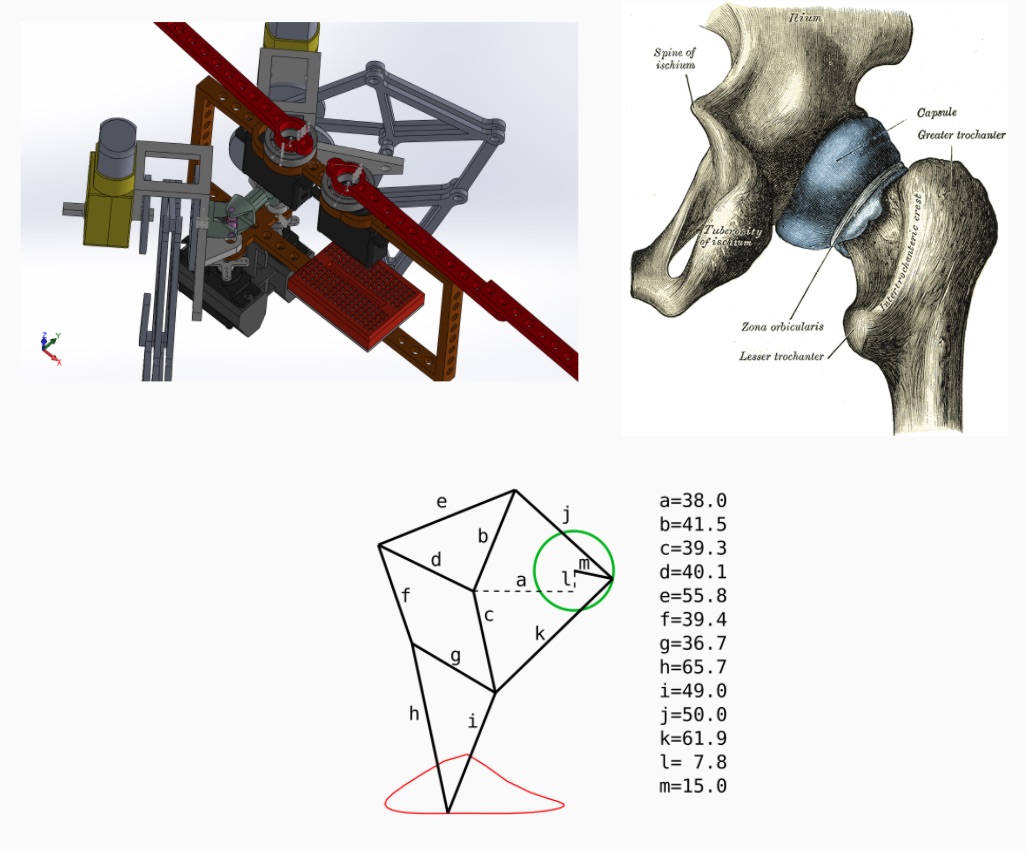
- Universal Joint (Similar to Human Hip)
- One of the creative solutions that we came up with came from the inspiration of how a hip moves, with the help of a universal joint.
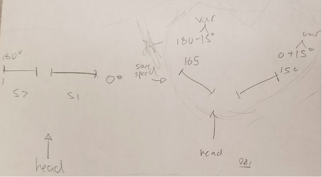
- Turning Capabilities
- With help of the previously stated universal joint, this would give our robot turning capabilities, with the help of servos
- Head/Tail
- The head and the tail would only be used for cosmetic purposes since moving them would cause too big of a shift in the center of balance.
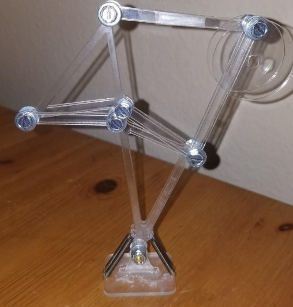
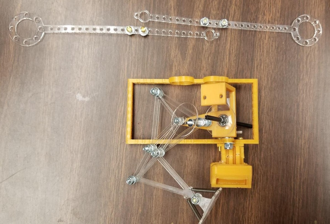
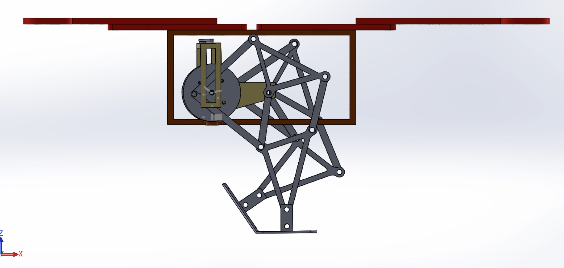
- Theo Jansen Leg Mechanism
- We decided to go with the Theo Jansen because it was a leg mechanism that rotated on a single axis which was ideal for our design since we were using DC motors.
- 3DoT Board
- Custom PCB
System Design
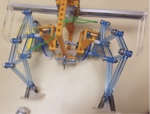
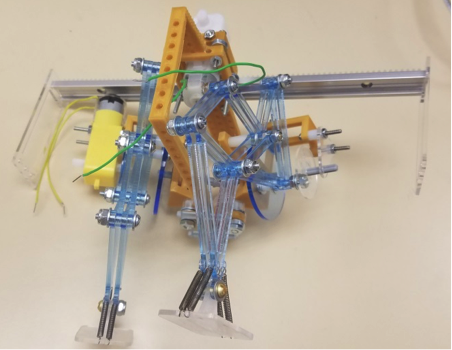
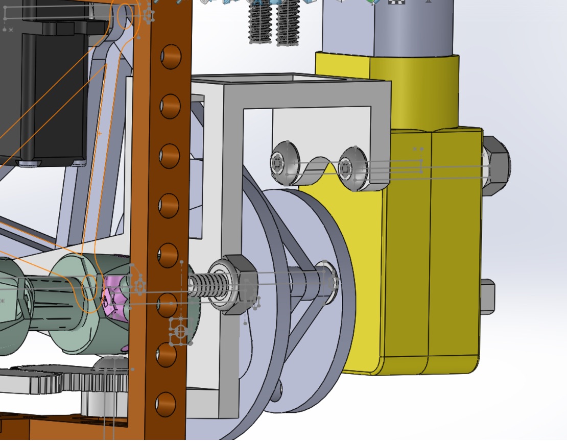
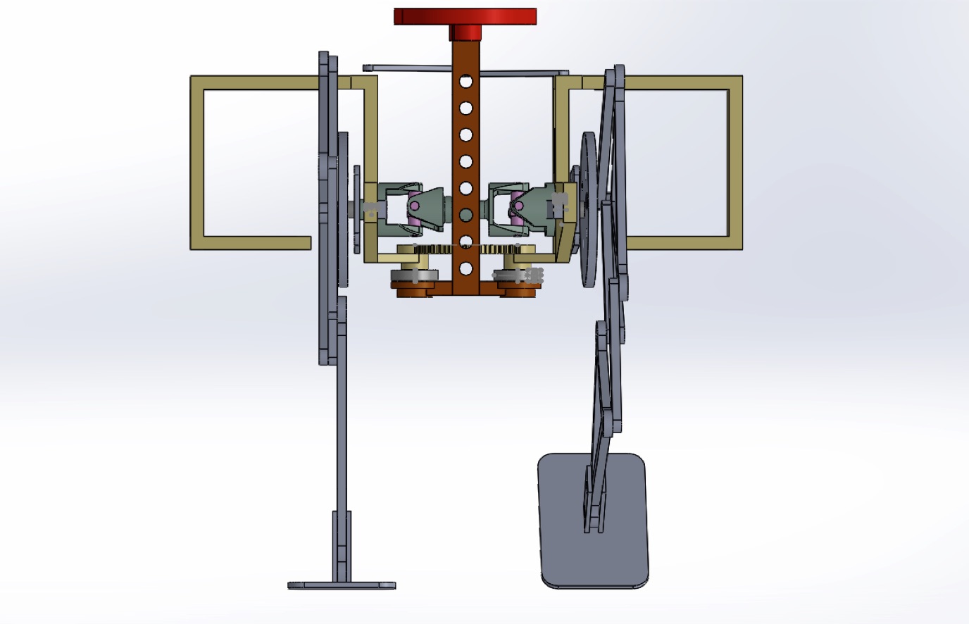
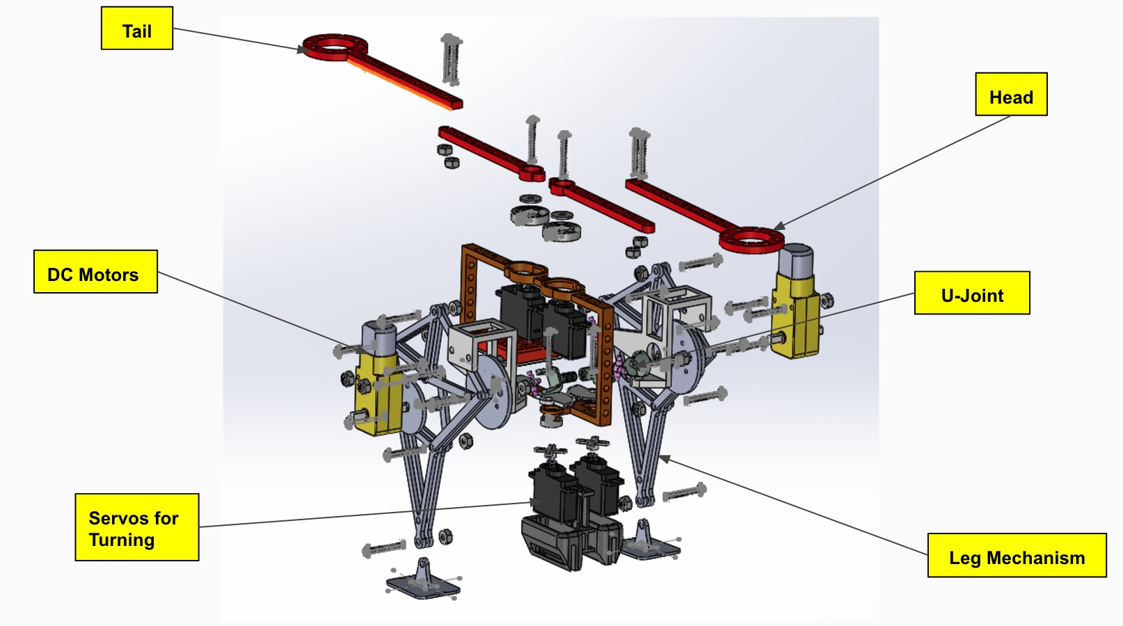
Below is an exploded view of the system design for our Velociraptor.
System Block Diagram
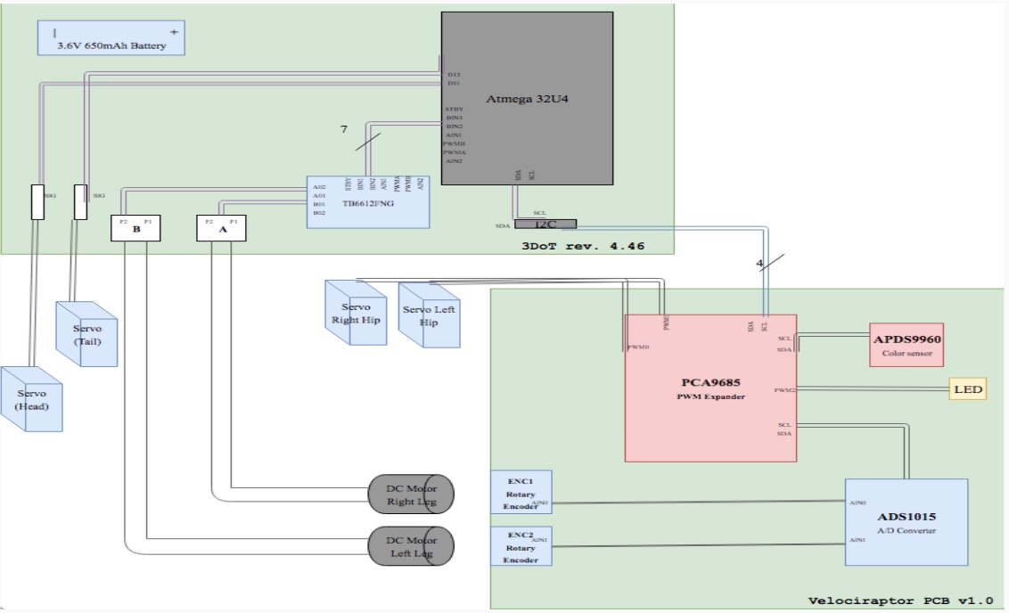
The system Block Diagram shows the inputs and outputs of our Velociraptor. It shows that our original design had a total of 4 servos and 2 DC motors, along with 2 rotary encoders for determining the velociraptor’s leg position. Ultimately this design was changed over and over as we went through the iterative design process. We ended up using only 2 DC motor and 2 servos, along with 1 rotary encoder to determine the position of the legs.
Subsystem Design
Experimental Results
We were able to test out and experiment on most of the driving factors of our robot. The following tests/experiments have been documented in blog posts with further information which can be reference to below.
Servo Torque Test
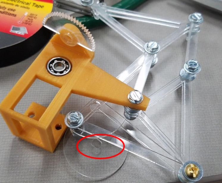
Leg Mechanism Prototype
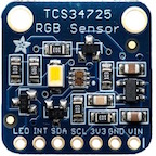
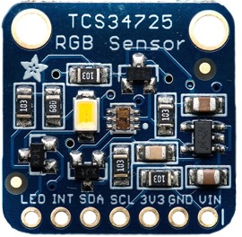
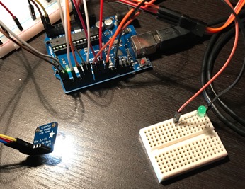
RGB Color Sensor
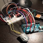
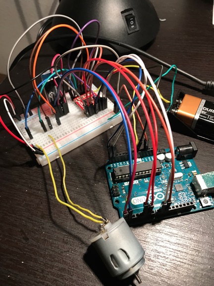
DC Motor “Move” Command
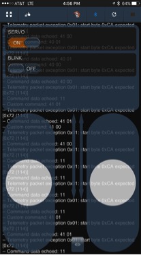
Servo Custom Commands
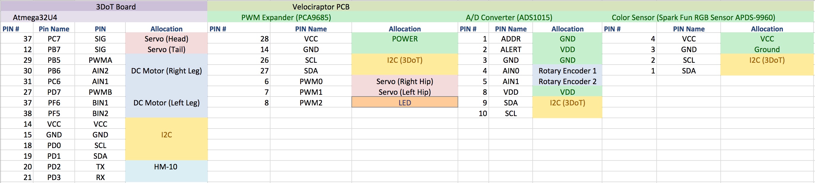
Interface Definition
In the figure below, is the interface definition matrix for our robot. It is important to keep this interface matrix updated and to also continuously keep track of all the revisions because as the design changes, it can have an affect on the resources that have been allocated in the previous design such as number of pins and hardware limitations. It might be a good idea to leave room on your custom PCB or Schematic in the case that the design changes and you need more pins available for a variety of thing (i.e. extra motors, new sensors).
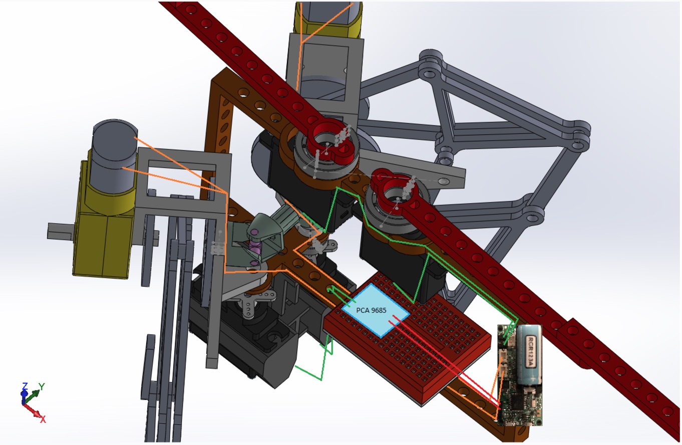
Cable Tree
Our Cable Tree was done through computed aided drawing which is not recommended. But as you can see below, we took into account the different things that would need to be mounted onto our robot like the 3DoT, the PCB, and the motors. One of the things we did not take into consideration was the slack that we would have to allow for the wires when turning the legs. Also, wire wrap is highly recommended to use in order to give the robot a cleaner overall look.
Mission Command & Control
Software Block Diagram
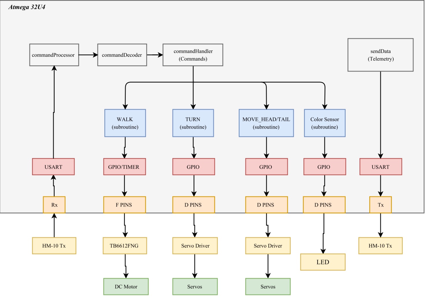
The Velociraptor software contains four different subroutines. Three subroutines control the robots movements and one controls the color sensor and LED. The software begins by first decoding incoming data packets, then each subroutine is called based on the decoded command in the commandHandler. Also please note that the subroutine for the Head/Tail movement was removed in the final design since we decided to use it for cosmetic purposes instead.
Electronics Design
There were a series of steps that had to be run through in order to choose the different types of parts for our robot. In the link below, we have a slide-set detailing the different parts that we used for our robot.
Firmware
The firmware design for the robot can be found in the following link below.
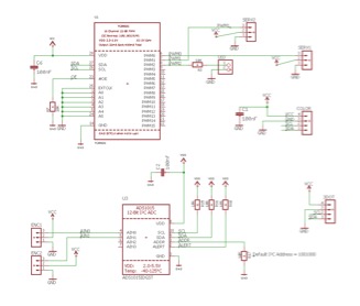
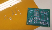
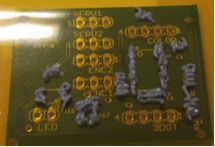
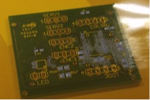
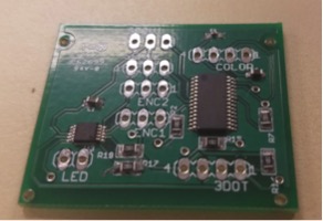
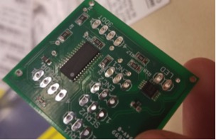
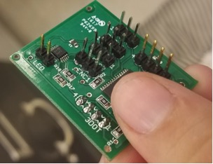
PCB Schematic/Layout
Included is a blog post that goes through the stages which our schematic, PCB, and construction went through during our project design.
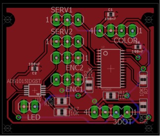
Finalized PCB Layout Design
Hardware Design
Below is a series of blog posts which takes you through the hardware design and assembly process that our manufacturing engineer went through as she continuously developed new designs and models through the engineering iterative design process.
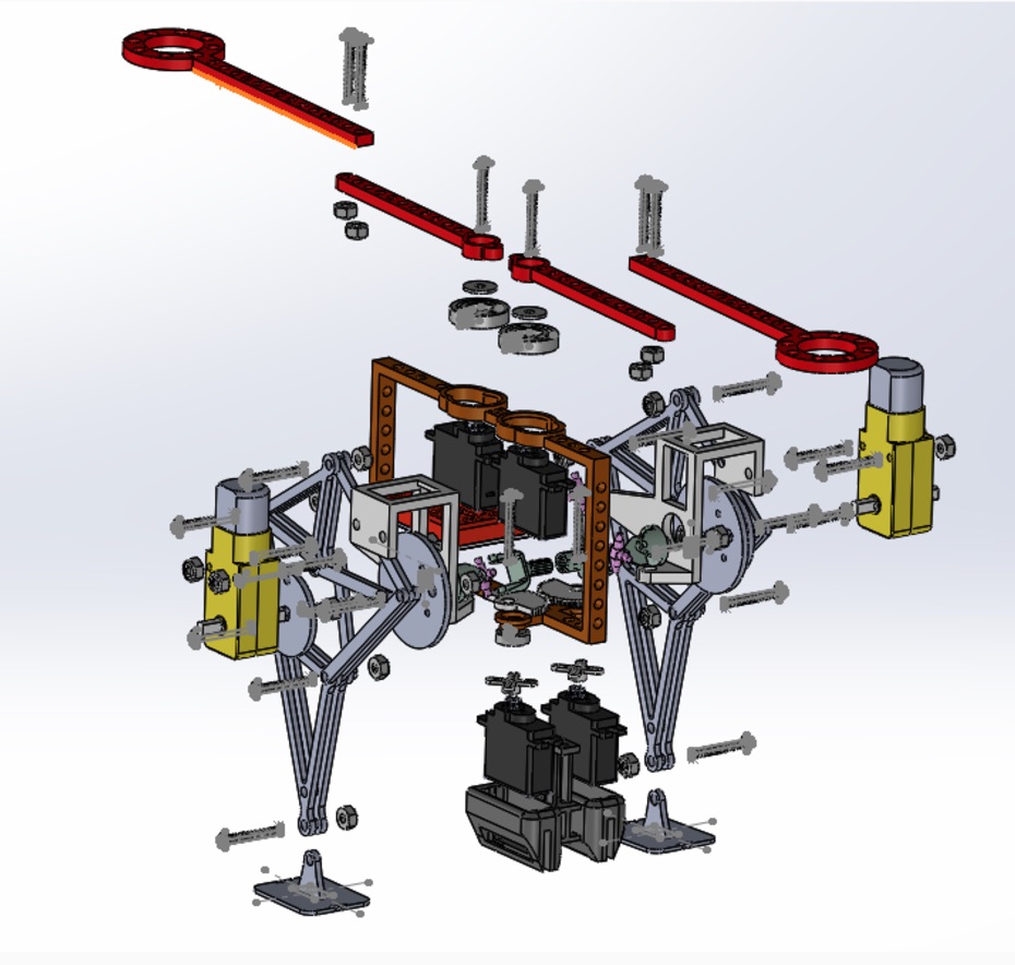
Exploded View of Velociraptor
Verification & Validation Test
Our verification & Validation test plan can be referred to in the link below. The other link includes the verification matrix detailing which requirements we were able to meet throughout the engineering design process.
Verification & Validation Test Plan
Project Status
Power Allocation
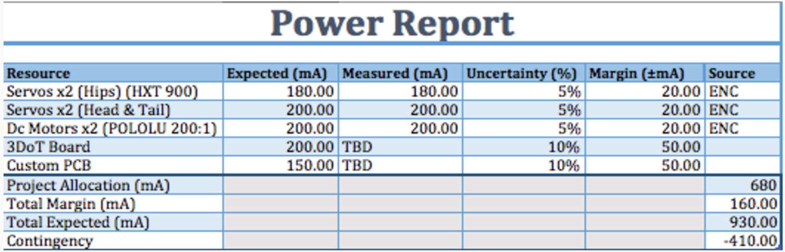
The Power Report shows that the Velociraptor team is at ~930mA and the Project Allocation is at 680mA. In this case we had a negative contingency which meant that we were allocating too much power to our original design. Later on, we ended up taking away some of the components such as DC motors and Servos which dropped our contingency for a positive note.
Mass Allocation
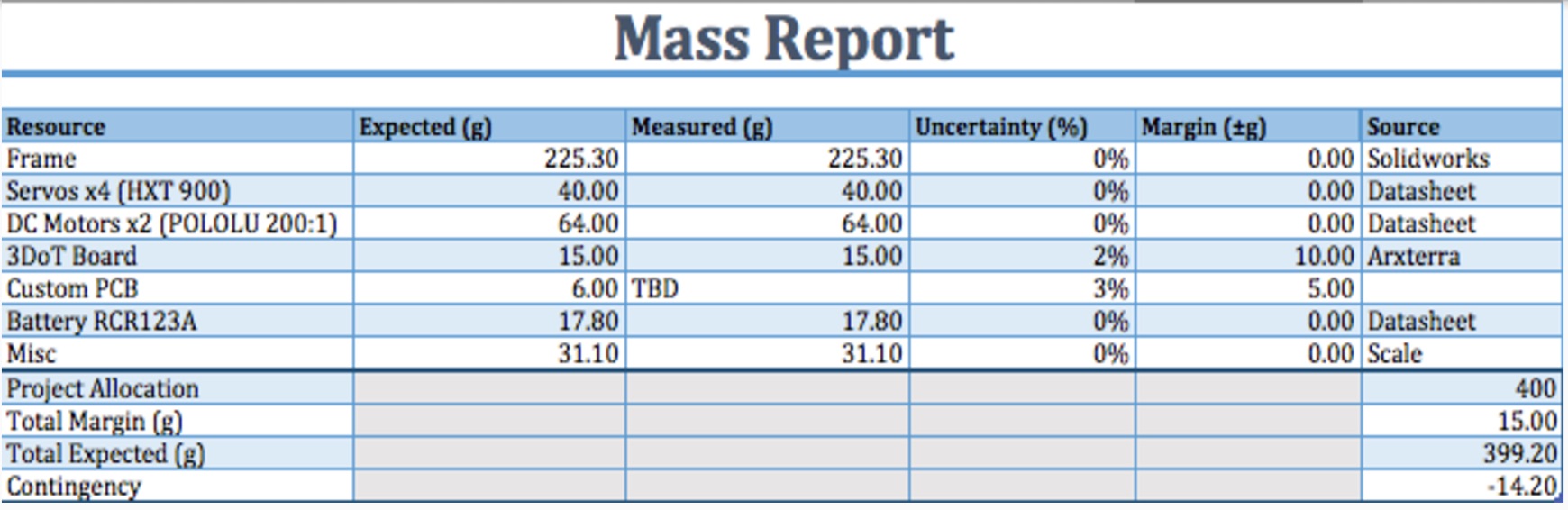
The Mass Report is based upon the torque needed to drive the robot, which is ~400g. The robot weighed 889g which was because we ended up decided to make the robot a lot larger in size than that of the original anticipated design.
Cost Report

Looking at the cost report above, we can see that we went well over our budget. We had an allocated budget of $200 originally and spent a total of $361.25 in the end. For future suggestions, it is better to do research on getting parts from personal vendors rather than distributors (i.e. McMaster Carr) in order to get parts for a cheaper price.
Updated Schedule
Top level
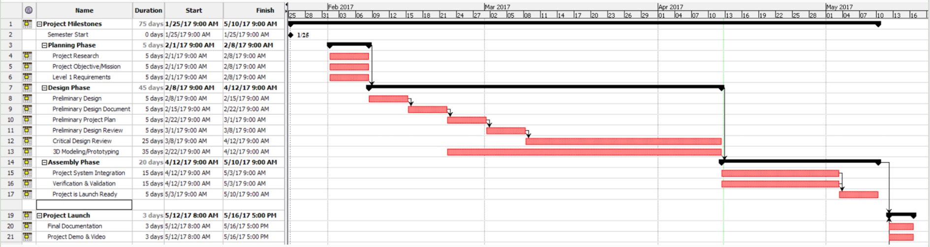
System/Subsystem Level
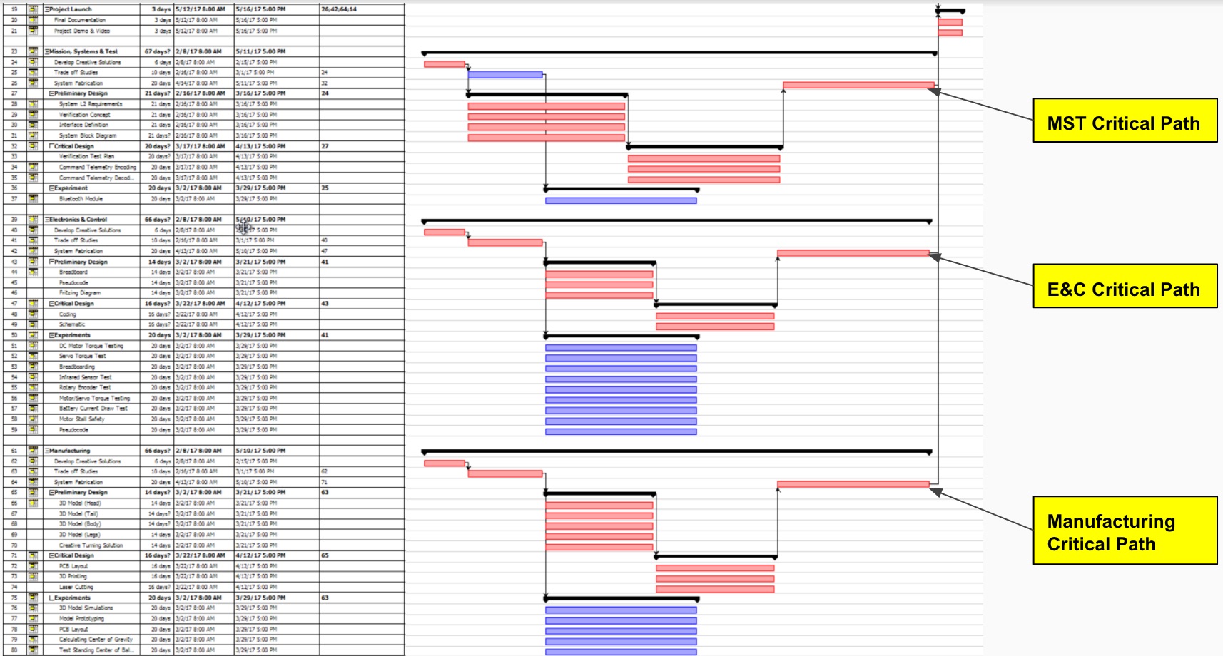
Much of the top level schedule had remained the same mostly throughout the duration of the project. This was mainly because most of the time we could not really push back important deadlines for the top level at all. As for the system level, this one tended to be very dynamic throughout the duration of the project since there was consistent design changes throughout the semester which continuously pushed tasks back.
Burn-down Report

The project overall started off very steady getting things done on time in the beginning since they were mostly top level tasks. Although as we started to dive into the system level tasks, we started to delve off-track which was tied to a lot of the iterative design changes we were making. In the end, we were not able to finish 100% of the tasks which we hope to which was caused to consistent errors and mistakes such as accidental drops or parts being burnt out from time to time. Expecting the unexpected and being prepared is suggested for future purposes because anything that can go wrong, will go wrong sometimes.
Concluding Thoughts
Lessons Learned / Future Suggestions
Below are a few suggestions for some of the things our group encountered as we went through the engineering design process for this project:
- Theo Jansen Leg Mechanism:
- Our team highly recommends that the Theo Jansen leg mechanism to NOT be used for future generations of any Bi-Pedal robot. The Theo Jansen leg mechanism was extremely difficult to deal with when it came to getting the robot to perform any type of walk. The Theo Jansen is more practical for other robots such as the spider-bot which has multiple legs.
- Position Tracking:
- When looking at the options that we had for position tracking, the one idea that we stuck with was the rotary shaft encoders. Dealing with the rotary shaft encoders was tough when it came to the wiring and placing them on the DC motor alone was also difficult since the cheapest encoder shaft we could find did not fit the motor shaft. So in this case we design an adapter to fit it. Look into hall sensors for future references, it may be simpler and give the robot a cleaner look.
- Material:
- Looking back at our design, it was not as strong as we hope it would be. We ended up using 3D printing and laser cutting for convenience purposes but realistically we needed a much stronger material. Ideally in the beginning we wanted to use aluminum to give it a clean look but it was way too expensive. Our suggestion is to find a way to laser cut all the parts because it will give a cleaner cut look to the robot and will also cut down manufacturing time. Laser cut wood or plastic would also be ideally stronger for the design so it isn’t too fragile.
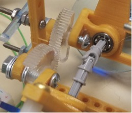
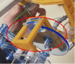
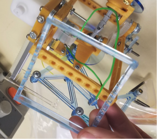
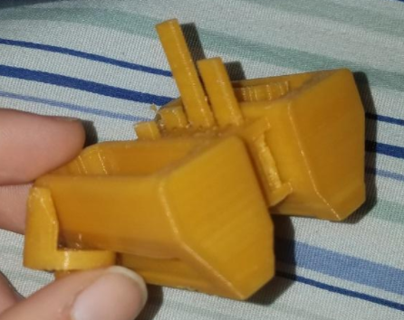
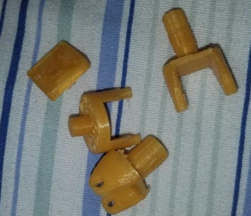
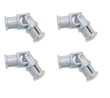
- Universal Joint:
- The Universal Joint worked amazingly well when it came to turning the legs in a 90 degree fashion while still being able to take a step. I highly recommend to continue to use the universal joint and incorporate it in future designs that require a turn.
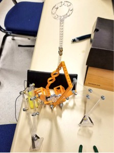
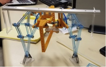
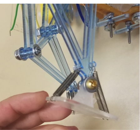
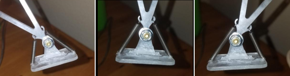
- Springs on the Feet:
- The Springs on the feet were very beneficial to our design as it gave almost full control of how we wanted to fix the feet in place. It is recommend to use more than 2 springs in future designs as you’ll see that ours only had two.
- Static Walking:
- The best advice that I can possibly give, considering it was our biggest challenge, is to focus a huge amount of your time into testing the robot to make sure it walks. The earlier you can get the robot to stand on its own and possibly even take a step, the more likely your project will be successful. We did not spend much time testing the robot to see if it could walk because we continuously kept changing the design. Sometimes, it’s best to stick with a design that is simple and full-proof but also satisfies the customers requirements
- Electronics:
- When beginning the course, please make sure that your E&C or someone on your team is good at coding in C++. This will be very beneficial for the team since it will push for faster prototyping. Also do not hesitate to reach out to the division managers who are there to be resourceful for things such as Code or Electronics in general.
Last but not least, please do ask Professor Hill for help since he did come up with idea at the end of our project which we should have came to him for in the first place. Using your resources and communicating across all management levels is extremely important.