LiPo Battery safety Spring 2016

Posted By: Luis Valdivia (Project Manager)

Written by: Kevin Nguyen (Electronics and Control)


Table of contents:

  • Introduction
  • Using the IMax B6AC LiPro Balance charger
    • Charging
    • Discharging
  • Using the Voltage monitor system
  • Battery safety bag


Introduction:

LiPo batteries are the most dangerous types of batteries in the world. They are very compact in size yet contain very high power. This high energy density allows them to power devices for longer periods of time compared to other types of batteries but also makes them very explosive. LiPo batteries may explode and catch fire if overcharged, undercharged, charged too fast, undercharged too fast, or punctured. Although this seems scary, if handled properly, LiPo batteries can be just as safe as any other battery and will outperform most other batteries. This blog post will help you minimize the risk and reap the rewards of LiPo batteries.LipoBattery safety

iMax B6AC LiPro Balance Charger:

Most LiPo explosion incidents happen due to improper charging. This manual will help the user become familiar with the B6AC Lipo Charger to charge or discharge the lipo battery for the UFO quadcopter. Here are step-by-step guides on how to charge and discharge using the B6AC charger.

Lipo charger


  • Charging
      • Power charger from outlet with AC to DC adapter.
        • Once the charger is plugged into the wall, it should automatically turn on.  
      • Sift through the different modes using the DEC./◀ and INC./▶ buttons and through the options using the START/Enter button .
      • Select battery type using the BATT. TYPE/Stop button.
        • Be sure to select the correct battery type. There are different techniques for charging different batteries. Choosing the wrong battery type may burn down your house.
      • Select charging mode.
        • The preferable charging mode is Balanced Charging since it charges all cells evenly. To be able to use this mode you must have a balance connector on your battery. This is used to detect the voltage levels of each individual cell so that the charger can charge the appropriate cells depending on its level.
      • Select charging current.
        • More charging current will result in a faster charge. The general rule is to use the same value as the rated capacity(i.e. 4500mAH = use 4.5A charging current). It is acceptable to select a lower charging current, but do not choose a higher charging current unless specified in your batteries’ specs. Charging current may be limited by your AC to DC adapter. Since our wall adapter was only capable of producing 1A, we charged with a 1A charging current which might take some time.
      • Select battery cell count.
        • i..e. 4 cell battery = 4S
      • Plug the balance connector into the appropriate location on your charger depending on the amount of cells of your battery.
        • Pay attention to polarity.
      • Connect positive and negative ends of battery to charger.
        • An adapter is necessary to connect the two.
        • Connect the adapter to the charger before connecting the battery; this is to prevent shorting the battery. Shorting for long periods of time may cause fires.
        • When disconnecting, take the battery off first before the adapter; this is to prevent shorting the battery.
      • Once everything is plugged in and the correct options are selected, press and hold the START button for 3 seconds.
      • A screen should appear showing the amount of cells the battery is reading vs. the amount of cells the user set for charging.
        • If these two values match(R=S), press START/Enter to begin charging.
        • Once the battery is fully charged, the battery charger will beep to alert the user. Never charge past 4.2V per cell.
        • When storing the battery, it is best to charge no higher than 3.7V.   
      • While charging, the DEC./◀ and INC./▶ buttons can be used to view total voltage or individual cell voltages.
      • Press the BATT. TYPE/Stop button to stop charging.


  • Discharging
  • Select battery type.
    • Select discharge mode.
    • Select discharge current.
    • Press and hold Start for 3 seconds to begin discharging.

Note: Charging and Discharging too fast may damage the battery. Double check the charging/discharging rates to make sure it is compatible with your battery.                


Voltage Monitor Alarm System:

To prevent the battery from discharging to dangerous levels, a voltage monitor alarm system is used to alert the user of low voltage levels. Below is a quick setup guide for the low voltage alarm.

Lipo alarm

  • Connect the Balance Charging Connector to the Alarm.
    • The back of the alarm has labels showing the connections of each pin. Make sure the polarity is correct.
      • Once the Alarm has been successfully installed, an initial beep will sound to indicate that it is operating properly.
  • Press button at the top of the Alarm to select the lower limit of the voltage level.
    • This voltage level is used to compare against each cell of the battery. Once a cell goes below this value, the alarm will go off until removed.
    • LiPo battery cells should never go below 3V. It is recommended to set the lower limit to 3.2V to give some cushion time to remove the battery from the device.
  • After the device is connected to the battery, the 7-Segment display will display the value of the battery as well as the value of each individual cell.


Battery Safety Bag:

safety bag

When not in use, it is recommended to store the LiPo in a battery safety bag. In the case of an explosion, these bags are flame retardant and will prevent the fire from spreading. Only one battery should be stored in each bag. If more than one is stored in a bag, the effectiveness of the bag will be reduced and risk of burning down your house will increase. Stop using batteries that appear to be damaged. Overcharging or undercharging may cause gases to leak and make the battery appear puffy. The chemicals in the battery will ignite when exposed to air.

Works Cited:

  1. “The World’s Most Dangerous Battery.” The World’s Most Dangerous Battery. N.p., n.d. Web. 26 Mar. 2016. <http://www.atbatt.com/batterytimes/dangerous-battery>.
  2. “A Guide to Understanding LiPo Batteries – Roger’s Hobby Center – Radio Control (R/C or RC) Cars, Boats, Airplanes, Puzzles, Plastic Models, & Trains – Saginaw, MI.” A Guide to Understanding LiPo Batteries – Roger’s Hobby Center – Radio Control (R/C or RC) Cars, Boats, Airplanes, Puzzles, Plastic Models, & Trains – Saginaw, MI. N.p., n.d. Web. 26 Mar. 2016. <http://www.rogershobbycenter.com/lipoguide/>.
  3. N.p., n.d. Web. <https://www.pololu.com/file/download/iMAXB6ACmanual.pdf?file_id=0J525>.

Project Preliminary Design Spring 2016 Millennium Falcon

By: Luis Valdivia (Project Manager)

Kevin Nguyen (Electronics and Control)

Juan Mendez (Manufacturing and Design)

Anthony Becerril (Mission, System, and Test)
Work Breakdown Structure

Capture


The Work Breakdown Structure (WBS) above outlines all the necessary work for the Millennium Falcon to succeed in meeting requirements. Each division has their own systems and subsystem tasks that must be done for project completion.


Project Schedule


  • Top Level Schedule


pLibre1

pLibre2

The top level schedule aligns with the WBS and outlines tasks to be done by each division as well as overall team tasks.


  • System/Subsystem Level Tasks


Division Task Details Completion Date
Mission, Systems, and Test LED Lightshow Programming Complete programming for customizable LED lightshow 3/10/2016
Arduino/ Programming Complete programming for arduino board to communication with quadcopter 4/4/2016
Android/iOS Application Successfully complete phone application compatible with Arxterra 4/4/2016
Verification Testing Create testing procedures, complete testing, and report results 5/3/2016
Electronics and Control New PCB Design revise previous design to be all on one board 3/4/2016
Battery Discharge Test create and complete battery discharge test 3/25/2016
Voltage Monitoring Test create and complete voltage monitoring test 3/28/2016
PID Tuning create successful PID tuning system 4/20/2016
Communication Verification Setup and verify communication with RC and bluetooth 4/27/2016
Manufacturing and Design 3D Model Create complete 3D model with parts 5/5/2016
PCB Stencil PCB printed and finalized by implement components 3/31/2016
Shell Mold Create quadcopter shell mold 4/29/2016
Shell Latching Implement latching system of shell to rest of quadcopter 4/29/2016
Component Assembly Complete assembly of quadcopter 5/2/2016
Parts Ordering Fully order all parts necessary for project
EDF Attachments Successfully create and attached various EDF attachments
  • Burn Down schedule

Burn down schedule chart display the total work remaining throughout the semester. As we progress, the percentage of work remaining will decrease.

Burndown

System Resource Reports

pOWER

mASS

Cost

Project Cost Estimate

The cost estimate comes from the cost report done within system resource reports and is inexpensive. Most of our cost going to renewing existing parts and adding modifying parts (e.g. servos). The costs are as follows:

Projection Allocation: $150.00

Total Margin:            $33.40

Total Expected Cost: $167.00

Contingency: $16.40

Spring 2016 Velociraptor: Servos

By Ashlee Chang (E&C)

Updated: 03/30/16

Table of Contents

Fulfilling Requirements

Level 2 requirements #7 is stated as follows:

7. For the Velociraptor to perform dynamic walking servos moving at a speed of 0.101 sec/10° shall be implemented to the chassis and thus meet the Project Level 1, requirement 5.

The servos will be the motor responsible for the walking and movement of the velociraptor in static walking, dynamic walking, turning, and walking up an incline. Below are the trade-off studies conducted, analyses on the best option, and the team’s final decision.

Servos Introduction

A servo is a handy device in robotics that converts electrical energy to mechanical energy. The device contains a two wire DC motor, a gear train, a potentiometer, an integrated circuit, and an output shaft. There are usually three wires attached to this device: a ground wire (which is usually black), an input voltage wire (which is usually red), and a control wire (which is usually yellow). Using the control wire, a coded signal is transmitted to the servo, which instructs the shaft to rotate to a specific angular position. The potentiometer can be thought of a variable resistor; its role in the servo is to monitor the angle of the shaft. If the shaft is not oriented at the correct angle, it will turn the motor to correct the direction. If the shaft is oriented at the correct angle, it will shut the motor off. A normal servo usually has the capability of positioning between the range of 0* and 180*.

pic1

Anatomy of a servo

The velociraptor will need eight servos: two for the head, two for the tail, and two for each leg. The two each on the head and tail will be for balancing purposes; left and right movements will be for balancing as each foot takes a step. The two per leg will be for not only walking, but a turning mechanism as well.

Calculations

pic2
Calculating servo torque

Torque is basically a “twisting force” and is measured in kg*cm. The larger this specification, the more force the servo can exert. If a servo has a power rating of 1 kg*cm, the maximum amount of power it will be able to apply with a 1 cm arm will be 1 kg.

In application to the velociraptor, an estimation for total weight must be made in order to justify the purchase of the servo. For the MicroBiPed, the servo power rating was 3.5 kg*cm at 6.0 V. Thus, for an arm of 1 cm, the servo would be able to produce a 3.5 kg push or pull force to the right angle of the servo arm before stalling. Due to the torque dependency on arm length, the joints of the velociraptor should be kept close to the body to maximize force capabilities. Below is the Titrus III legs showing the arm lengths.

pic3
Titrus III arm lengths

The first prototype of the servo has a front arm length of 5.2 cm and back arm length of 2.0 cm. Using these numbers, calculations are made in the “Update” section of this blog post to calculate exactly how much weight each arm alone can handle. The Titrus III is credited and can be seen in action here: https://www.youtube.com/watch?v=GxVv4WNlXMA.

Trade-off Studies

In order to better assess the appropriate servo to use for the velociraptor, a comparison chart was made below of servos in the marketplace.

pic4
Servos comparison table

pic5
All servos, as per order in the comparison table

* The difference between the two Futaba servos is one has a bearing type of dual bronze brushings, and the latter has a signal ball bearing system.

The first listed servo is the one used by last semester, and the second is one with a lot of torque but Dr. Hill suggested not to go with. 11 different servos were compared, listing some of the most important characteristics. The velociraptor will need eight, so it is important to keep the cost of individual servos at a minimum. The operating speed shows how long it takes for the servo shaft to rotate 60*. It can be seen from the table that all operating speeds are relatively close in value, thus it will not be a major deciding factor. The stall torque is also an important parameter, which shows how much force is needed to move the shaft over a certain distance. In the case of a heavy velociraptor, the stall torque becomes a very important parameter as more torque is needed. The dimensions will affect how large the body encasing them will be. This information is important to M&D division for the size and shape of the body. Lastly, the weight is also significant, considering there are many servos to be accounted for.

Observing the MicroBiPed, weight was undoubtedly the biggest problem. The choice of material used to construct the shell of the robot, PLA, made the overall “micro” robot very heavy as a result. The torque of the servos was not sufficient enough to power through the weight of the MicroBiPed. Thus, it is important that the velociraptor team is weight-conscious in selecting not only the material used to construct the shell, but also the individual component pieces. Below is a table comparing the stall torque to weight ratio of each component. Also below is the price to torque ratio.

pic6
Stall Torque/Weight Ratios

pic7
Price/Weight Ratios

Links to all the products:
[Towerpro MG92B] http://www.headsuphobby.com/Towerpro-14g-MG92B-Digital-Metal-Gear-High-Torque-SubMicro-Servo-A-537.htm
[JX PDI-6221MG20KG]  http://www.banggood.com/4X-JX-PDI-6221MG-20KG-Large-Torque-Digital-Coreless-Servo-For-RC-Model-p-1031156.html
[Futaba S3003] http://www3.towerhobbies.com/cgi-bin/WTI0001P?I=LXH288&P=8
[RioRand ES08MA] http://www.riorand.com/toys-hobbies/helicopters/riorandr-es08ma-9g-mini-metal-gear-servo-upgrade-mg90s-for-trex-align-450-rc-helicopter-e.html
[TowerPro SG90] http://www.amazon.com/J-Deal%C2%AE-TowerPro-Helicopter-Airplane-Controls/dp/B00X7CJZWM/ref=sr_1_1?ie=UTF8&qid=1455438532&sr=8-1&keywords=servos
[Hitec HS-311] http://www.headsuphobby.com/Hitec-43g-HS-311-Standard-Servo-B-560.htm?categoryId=-1
[Futaba S148] https://www.servocity.com/html/s148_standard_precision.html#.VsBN_fkrKM-
[Futaba S3004] https://www.servocity.com/html/s3004_standard_ball_bearing.html#.VsBOBPkrKM-
[Power Up AS3513NG] http://www.headsuphobby.com/Power-Up-25g-AS3513NG-Analog-Mini-Servo-W-350.htm?categoryId=-1
[Power Up AS3125NG] http://www.headsuphobby.com/Power-Up-38g-AS3215NG-Analog-Standard-Servo-W-400.htm?categoryId=-1
[Emax ES3051] http://www.headsuphobby.com/Emax-43g-ES3051-Digital-Standard-Servo-G-651.htm?categoryId=

Arduino Application

The servo library can be found on the Arduino website, which supports up to 12 different motors on most boards and up to 48 on the Arduino Mega. The Mega can handle up to 12 servos while the Mini can only handle 6-7, so the Mega might be in this semester’s project’s best interest. Two example codes are listed on the Arduino servo website for controlling the position of a servo with a potentiometer and for sweeping the shaft of the servo motor back and forth.

There are three different output types: analog voltage, PWM, and serial. Servo motors use the communication type of PWM (post width modulation). The length of a pulse in seconds will determine how many degrees the motor will turn, and in turn, dictates the angle of the output shaft.

pic8
Pulse duration’s relationship to shaft angle

Conclusion

Seeing as the velociraptor will require eight servos, it’s important to minimize weight as much as possible. The servo choice of the MicroBiPed provides the largest torque to weight ratio compared to all other options listed in the table. It’s even more notable that the dimensions are the smallest as well, which will keep the velociraptors body containing most of the servos sizable. To maximize the power ratings of the servos, the arm lengths should also be designed short.

Update (03/14/16)

After the systems and test engineer estimated the project to be around 350 g, torque calculations were able to be made to see exactly how much weight a single servo can handle. The front and back legs (“arm” joints) of the first prototype are 5.2 cm and 2.0 cm, respectively. Using the torque of the TowerPro MG92B servo at 3.5 kg*cm, it is calculated that the front servo alone can handle a weight of approximately 675 g and 1750 g, respectively. This is a basic calculation; of course there are other things to take into consideration like weight distribution of the velociraptor and the fact that some servos work together at the same time. However, this calculation shows that if a single servo can handle the weight of the entire project, then more than one servo (some working together simultaneously) definitely has enough torque to handle the project and then some. The total weight of the project, as estimated by the S&T engineer, is around 500 g. Thus, the TowerPro MG92B was the chosen servo for the velociraptor. All eight servos together come to a total of $60. This servo, also used by last semester’s MicroBiPed, also has the best torque-to-price and torque-to-weight ratio.

Works Cited

[1] What is a servo?
https://www.servocity.com/html/what_is_a_servo_.html#.VsAzEvkrKM8
[2] What’s a servo?
http://www.seattlerobotics.org/guide/servos.html
[3] How to Arduino #3 – Servos
youtube.com/watch?v=ybV8vitYAWU
[4] Servo Power & Speed
https://www.servocity.com/html/servo_power___speed.html#.VsBO9vkrKM8
[5] Understanding RC Servos: Digital, Analog, Coreless, Brushless
http://www.rchelicopterfun.com/rc-servos.html
[6] Servo library
https://www.arduino.cc/en/reference/servo
[7] Titrus III
youtube.com/watch?v=GxVv4WNlXMA

Spring 2016 Velociraptor: Sensors

By: Ashlee Chang (E&C)

Updated: 04/05/16

Table of Contents

Fulfilling the Requirements

Level 2 requirements #9 and #10 are stated as follows:

9. For the Velociraptor to have the ability to travel up a 6.5-degree incline, a gyroscope/accelerometer shall be implemented to preserve the chassis balance and thus meeting the Project Level 1, requirement 6.

10. In order for the robot to detect obstacles at a range of 20 cm in its path, an ultrasonic sensor shall be implemented to the build of the Velociraptor and thus meeting the Project Level 1, requirement 7. 

Thus, the two sensors that will be implemented on the Velociraptor will be an ultrasonic sensor and a gyroscope/accelerometer. Below are the trade-off studies conducted, analyses on the best option, and the team’s final decision.

How the Sensors Work

Ultrasonic Range Finder

Ultrasonic sensors use a process called echolocation, which uses sound as a form of location. A high frequency sound wave is generated; the time it takes for the sound to bounce off an object and back to the sensor determines the distance away from the object it is.

Gyroscope/Accelerometer

A gyroscope/accelerometer is a device to measure acceleration forces. Using this information, one can determine the plane at which the robot is tilted at with respect to Earth. It has crystal structures contained within it that generates vibrational stress to acceleration, inducing a voltage level reading.

Trade-off Studies

Ultrasonic Range Finder

tradeoffultrasonic

Ultrasonic Sensors Comparison

The first option is the component used for last semester’s MicroBiped. The neck and head length of the velociraptor will be approximately 15-20 cm long, which is the minimum distance the ultrasonic sensor must be able to detect. All of the ultrasonic sensors compared have at least a 2 cm minimum range. The velociraptor must be able to respond to an object forward-facing it, most likely 5-10 distance away from the end of its head. All of the maximum ranges for the ultrasonic sensors are well over 400 cm, which makes any of the options fine. Most standard sensors have a dimension of 50 x 15 x 14 mm, weight 10 g, need a 5 V power supply, and generate ultrasonic waves at 40 kHz. The resolutions range from 0.3 to 1 cm, all which are exceptional as the Arduino coding can be set up to respond at any point. The angle at which the echoes can bounce back is documented in the last column of the table. The RB-See-90 has an angle measurement double than the other ultrasonic sensors, but is also 5x the price. As demonstrated below, as the velociraptor approaches the hindering obstacle, the obstacle takes up a wider view within the vision of the ultrasonic sensor. Thus, a measuring angle of 15* is sufficient. These ultrasonic sensors use a PWM interface; a 10 micro-s pulse will initiate the ranging, and a pulse duration is outputted based on if and how far an object is away. The calculation for distance is Distance = [(Duration of high level)*(Sonic 340 m/s)]/2.

pic3

Measuring Angle and Distance

  • List of Products:

[SainSmart HC-SR04]: http://www.sainsmart.com/ultrasonic-ranging-detector-mod-hc-sr04-distance-sensor.html

[Banggood HY-SRF05]: http://www.banggood.com/HY-SRF05-Ultrasonic-Distance-Sensor-Module-Measuring-Sensor-Module-p-91444.html?currency=USD&createTmp=1&utm_source=google&utm_medium=shopping&utm_content=saul&utm_campaign=Electronic-xie-us&gclid=CK7pwoHpissCFYVCaQodpXIBbw

[GearBest HC-SR04]: http://www.gearbest.com/development-boards/pp_58067.html?currency=USD&gclid=CIeQwMrsissCFYM8aQodFM4FOw

[SeeedStudio RB-See-90]: http://www.robotshop.com/en/seeedstudio-ultrasonic-range-finder.html?gclid=CJ7LmePtissCFYSDaQodBvQOsg#productsReviewBoxTitle

[MaxBotix MB1030]: http://www.maxbotix.com/Ultrasonic_Sensors/MB1030.htm

Gyroscope/Accelerometer

gyroacceltradeoff

Gyroscope/Accelerometers Comparison

With accelerometers, there is a trade-off between the measuring range and its sensitivity. A smaller range will provide a more accurate reading, but won’t be able to handle higher velocities, and vice versa. For stationary tilting. Range notation is written as +#g. For tilting, +1.5g is recommended, robots +2g is recommended, for sudden stops +5g is recommended, and for vehicles such as a spaceship +250g is recommended. So the choice in range for the velociraptor should at least +2g. The weight and dimensions of the accelerometers are all similar, and won’t be a factor in the final decision. Ideally, a PWM output type would be ideal to work with in the Arduino because of its simplicity. However, all accelerometers researched seemed to either have an analog or a serial interface; the serial interface uses SPI (serial peripheral interface) and I2C (inter-integrated circuit). The E&C division manager recommended not to use such interface as it is difficult to master dealing with such data. Analog Device’s ADXL335 supports an analog interface, which will provide data that will be easy to work with.

  • List of Products:

[Freescale Semiconductor MMA8451]: https://www.adafruit.com/products/2019?gclid=CISlz8P1issCFQmQaQodjKwLqQ

[Freescale Semiconductor MMA8452Q]: http://www.robotshop.com/en/triple-axis-accelerometer-breakout-board-mma8452q.html?gclid=CNfjjqWEi8sCFQmqaQodNSYPGQ

[Analog Devices ADXL345]: https://www.adafruit.com/products/1231

[Analog Devices ADXL335]: https://www.sparkfun.com/products/9269

[Kootek GY-521]: http://www.amazon.com/Kootek-MPU-6050-MPU6050-sensors-Accelerometer/dp/B008BOPN40

Conclusion

pic5

GearBest HC-SR04 and Analog Device ADXL335

The sensors the velociraptor team would like to go with are GearBest’s HC-SR04 ultrasonic sensor and Analog Device’s ADXL335 accelerometer. The former was chosen based on an economical decision, as all ultrasonic sensors met the requirements in distance detection, resolution, and angle sensitivity. The latter was chosen because it not only has a more than sufficient measurement range of +3g, but also outputs analog data, a much easier interface to work with over SPI and I2C.

Update: Due to unforeseeable circumstances, the velociraptor team had to make some changes regarding the sensor choices. In regards to the ultrasonic sensor HC-SR04, the sensor was no longer functional once the object in front was out of range capability. Most HC-SR04s cheaply manufactured in China overlooked this important flaw. Once a high frequency wave was sent out, the sensor would standby and wait until this wave bounced off the object and returned. With no object in front of the sensor, the HC-SR04 would continue waiting. A clap of the hands or even shaking the sensor would act as a return signal, and the Arduino serial monitor would stop returning the error value -1. This is why the velociraptor team decided on investing in a nicer, better quality rangefinder that met the velociraptor requirements. The E&C division manager had a quality ultrasonic sensor on-hand, which our team purchased. For the gyroscope/accelerometer, there was miscommunication on what sensor was to be used for sensing orientation. Initially the team was told to use an accelerometer, hence the ADXL335 choice. However a couple weeks ago, the team was informed that a gyroscope was to be used, as analog inputs are actually more difficult to handle. Testing the GY-521 gyroscope/accelerometer combination board, a sample code was uploaded provided online, which was hundreds of lines long, using serial output type. Upon uploading to the Arduino, the code took up over an outstanding 50% of flash memory. Because the current walking code and Bluetooth code are approximately 20% each already, the team saw using this serial output type orientation sensor as unfeasible. Therefore, the team is sticking with the ADXL335 choice. Both the MaxSonar ultrasonic sensor and ADXL335 accelerometer codes have been tested and work successfully with some degree of accuracy.

IMG_4506

MaxBotix LV-MaxSonar-Ez3 MB1030 and Kootek GY-521

Works Cited

[1] Ultrasonic transducer: https://en.wikipedia.org/wiki/Ultrasonic_transducer

[2] Accelerometer: https://en.wikipedia.org/wiki/Accelerometer

[3] A beginner’s guide to accelerometers: http://www.dimensionengineering.com/info/accelerometers

[4] Accelerometer, Gyro and IMU Buying Guide: https://www.sparkfun.com/pages/accel_gyro_guide


Spring 2016 Velociraptor: Material Trade-Off Study

By Mingyu Seo (Manufacturing & Design)

Approved by Khoi Vu (Project Manger)

For the Velociraptor Project, we have considered several materials for manufacturing prototypes as well as for our final robot. The chart shows advantages and disadvantages of the material, to help us consider the different materials we’ll use for the velociraptor:

Capture

Through careful consideration, we chose to use 3D material to build our prototype. Using a 3D printer will give use the advantages of faster printing speed, quick solidification, and are easily accessible. 3D materials shown above such as PLA, ABS, and PVA are flexible, strong durability, and have sharp printed corners which are made for ideal small parts. Although the plastic material may have lower temperature resistance compare to Aluminum, building a prototype with a 3D model will let us make adjustments by applying heat to it.  We have considered using PLA (Polylactic Acid) material due to its advantages of sharper printing corners, low material cost, maximum printing speed, and accessibility on campus. All 4 materials were considered as a possible material for our final robot. But Aluminum was chosen to be used as the material to build the final robot due to its economical, strong durability and non-magnetic/electrical conductive traits. Due to aluminum’s disadvantages of the necessity of specific printing machine and non-malleability, our team has considered it should be used after finalization of the dimension of our robot in order to minimize cost as well as time.

Spring 2016 Velociraptor: Course Analysis

By Khoi Vu (Project Manager)

IMG_0047 (2)

Figure 1: Actual Course

This is the analysis of the course in which the Velociraptor biped robot will need to complete. This course contains multiple surfaces that the robot will need to be able to walk on. Furthermore, the course will also have an obstacle that the robot will lift its leg high enough to walk over. It will also encounter another obstacle that it will have to avoid and navigate itself around it. This obstacle will be the size of a textbook.

Surfaces:

1.The first surface the robot will encounter will be linoleum. The coefficient of friction of linoleum tiles will vary from 0.3 to 0.5 depending on the amount of waxed that is on the tiles. (Refer to works cited 1)

12

Figure 2: Linoleum Tiles


2.In the second surface, the robot will encounter is a 3.5 cm rubber bar with the height 0.3 cm. According to the Engineer’s Handbook, the coefficient of friction between rubber and a solid is 1.0. The rubber bar separates the Linoleum tiles and Berber Carpet.(Refer to works cited 2)

IMG_0047

Figure 3: Rubber Bar


3.Finally, the robot will also walk on Berber Carpet for the remainder of the course. The carpet has a 0.58 as its coefficient of friction. (Refer to works cited 3)

IMG_0557Figure 4: Berber Carpet


course

Figure 5: Measured Course Using SolidWorks

IMG_0594

Equation 1: Calculation of the Incline angle

In Equation 1, the formula calculates the angle of the incline of the course by measuring the adjacent side of the angle and the maximum height of the ramp.

Works Cited

  1. http://www.floorcare-usa.com/pdf/CoefficientFriction.pdf
  2. http://www.engineershandbook.com/Tables/frictioncoefficients.htm
  3. http://www.am20.com/pdf/AthleticFloor8pg.pdf

Spring 2016 Velociraptor: Preliminary Project Plan

Khoi Vu (Project Manager)

Camilla Jensen ( Systems and Test Engineer)

Table of Contents

Work Breakdown Structure

Figure 1 describes the work distribution for project Velociraptor. There are three branches which consist of Mission, Systems, and Test, Electronics and Control, and Design & Manufacturing. Each branch has its unique work breakdown headed by individual engineers. All three branches will be overseen by the Velociraptor’s Project Manager


WBS

Figure 1

Project Schedule

Top Level Schedule

The charts shown below are the preliminary work schedule that Velociraptor’s team members are assigned. Each task has a start and a deadline that must be completed. Tasks are divided based on the Work Breakdown Structure (WBS) in figure 1.

Capture

Figure 2

gantt

Figure 3

Burn Down and Project Percent Completion

The burndown chart provides an insight on the hours of  work that had been contributed and the remaining hours that are needed to complete the project. This chart shows how productive the team has been for the past two months.

Screen Shot 2016-02-23 at 9.11.25 PM

Figure 4

System/Subsystem Level Tasks


Camilla Jensen (Systems Engineer)

1.  Learning C++ programming language to write algorithms using the Arduino IDE to

decode instructions to the Velociraptor from the Arxterra Application on an Android

device.

2. Learning how to use the HC-06 Bluetooth wireless device and configure with the

Arxterra Application.

3. Generated system resource reports (Mass, Power and Budget) that will define the size of

battery for Velociraptor.

4. Will work with E&C to optimize walking codes for Velociraptor.

5. Will create verification and validation test plan and perform tests to ensure each device

meets all defined requirements.


Ashlee Chang (Electronics & Control Engineer)

1. Research servo options and conduct a trade-off study to select the most fitting servo to handle the total mass of the velociraptor.

2. Research sensor options and conduct a trade-off study to select the most fitting ultrasonic sensor and accelerometer to meet the object detection and adaption to incline requirements.

3. Generate a fritzing diagram with all electrical components to map out all wire connections and testing on a breadboard

4. Prepare a circuit schematic in Eagle CAD that will be passed on to M&D for manufacturing

5. Research power subsystem requirements, selecting an appropriate battery, and meeting the specific voltage and amperage requirements of each component

6. Test the PCB to ensure all electrical components are fully operational.

7. Write the Arduino C++ walking code to control the servos; this includes static walking, dynamic walking, adapting to an incline using the accelerometer sensor, being able to turn in response to an object hindrance

8. Work with S&T on the interfacing between the velociraptor Bluetooth and Arxterra app


Mingyu Seo (Manufacturing & Design)

1. Create a complete 3D model of the Velociraptor by using Solidworks for the prototype.

2. Perform stress analysis, Center of Mass, and breaking points to determine the acceptability of

the robot.

3. Build a prototype for Electronics and Systems Engineer to validate MCU subsystem & Control

Firmware as well as for final robot validation.

4. Fabricate the PCB design provided by Electronics Engineer and order an SMT solder paste stencil.

5. Manufacture mechanical parts for velociraptor using the laser cutter.

6. Specify and order off-the-shelf parts for final assembly of the robot.


System Resource Reports

Since the goal for this semesters Velociraptor was to reduce the mass from last semesters MicroBiped, the project allocation has been set to 1.00kg and thus reduce the bulkiness and increase stability for the robot.

Mass

Figure 5: Mass Report

In the figure below (figure 6) presents the estimated power consumption of the Velociraptor biped robot. The majority of the power will be consumed by the eight servos that is used to provide torque for movement of legs, tail, and head.

Power

Figure 6: Power Report

Project Cost Estimate

Cost

Figure 7: Estimated Project Cost

Figure 7 is the estimated cost that will be required to manufacture the Velociraptor biped robot. The margins of the Cost Report displays an estimated price for shipping. Many of the parts had free shipping or it was included in the price of the product. The Battery charger’s  shipping costs were 4 times the cost of the charger since it’s shipped from China.

Spring 2016 Millennium Falcon Preliminary Design Document

BY:

Luis Valdivia (Project Manger)

Anthony Becerril (Systems Engineer)

Juan Mendez (Manufacturing Engineer)

Kevin Nguyen (Electronics Engineer)

Table of contents: 

  • Program Objective 
  • Level 1 Requirements
  • Level 2 Requirements
  • Design Innovation
  • Subsystem Requirements
    • Product Breakdown Structure
    • Electronics System Design
      • System Block Design
      • Interface Definition
    • Manufacturing Design
  • Design and Unique Task Descriptions


Program Objective:

The Program Objective of the Millennium Falcon is to produce a safe, low cost, and durable quadcopter using ducted fans. The Millennium Falcon quadcopter will allow user friendly connectivity to an RC controller or any smartphone device using the Arxterra application. The project shall explore multiple innovative design solutions for yaw control leading to stable flight during operation of quadcopter. Stable horizontal flight control will also be addressed, as a design feature. The aircraft will resemble the famous spaceship from the Star Wars movie franchise with a newly designed shell and programmable lights.

Mission Profile:

The Mission Profile for the Millennium Falcon is to complete a flight course outside out CSULB property. The Millennium Falcon quadcopter must maintain stable flight as it circles around a tree in the field across the Whaley Park Community Center. Before attempting flight, the aircraft must be registered with the Federal Aviation Administration to ensure a safe environment for others.  

Level 1 Requirements:

  1. The Millennium Falcon quadcopter team, aims to maintain flight stability.
  2. An enclosure box will protect battery.
  3. A new Printed Circuit Board (PCB) must be re-designed.
  4. New shell for aircraft intends to resemble aesthetic requirements.
  5. Millennium Falcon quadcopter must have longer landing legs to support vehicle.
  6. Quadcopter is expected to implement user input from wireless communication.
  7. The Millennium Falcon quadcopter must display a programmable light show during flight.
  8. Quadcopter will perform designated flight path while meeting safety requirements
  9. Purchases and services for material items must not exceed budget.


Level 2 Requirements:

  1. The Millennium Falcon quadcopter team, aims to maintain stability by using a fifth Electric Ducted Fan (EDF) for yaw rotation control. If side fan solution is not implemented, EDF orientation, specifically bracket angle, will be optimized for Millennium Falcon quadcopter stability during flight.
  2. A battery enclosure box must structurally support the weight of the battery and protect it from impact.
  3. New PCB will be required to keep all wiring internal and not exposed. Crystal oscillator, resistors, capacitors will be internally designed contrary to previous semesters design.
  4. New shell casing will meet aesthetics by resembling the Millennium Falcon spaceship from the Star Wars movies. New shell casing also will feature a latching system to secure shell onto Millennium Falcon quadcopter frame.
  5. Removable landing legs must support the entire weight of the vehicle and lift it at least one inch off the ground.
  6. Wireless control of the Millennium Falcon quadcopter will be done by communicating via the Arxterra smartphone application supported on both android and apple as well as via bluetooth remote control.
  7. The Millennium Falcon quadcopter light show must be customizable via Arxterra smartphone application.
  8. The Millennium Falcon quadcopter will perform designated flight path at the CSULB traffic circle while meeting requirements set by the Federal Aviation Administration (FAA) , Unmanned Aircraft Systems (UAS) and College of Engineering (COE).
  9. All purchases and services cannot exceed $400.00 with the guidance of project manager and customer approval.

Design innovation:

Below you can see the creative design process used in the creativity exercise.

Creative solution for vehicle protection: 

Creative Desing

Creative solution for controlling yaw rotation:

Creative Desing2

Subsystem Requirements:

Product Breakdown Structure (PBS):

Below in the product breakdown structure, all components of focus are outlined with details explaining their purpose.

pbs

Electronics System Design:

Wireless Communication

  • An RC control will be created to control the Millennium Falcon quadcopter.
  • A smartphone application will be implemented to control the Millennium Falcon quadcopter. This application will be compatible with android and apple mobile devices.

Light Show

  • Light show must be controlled through Arxterra application.

5th Ducted Fan

  • 5th EDF must have enough thrust to counter the yaw rotation.

Battery

  • Since 5 EDFs are used this semester, battery must be able to supply power to 5 motors.  

New PCB

  • All components must lie within the PCB.

System Block Diagram:

sys block


This is the Signal Block Diagram for the Millennium Falcon Quadcopter. To maintain stability during flight, the microcontroller will constantly read data from the sensors and the data would then be analyzed using a PID algorithm. The PID controller would determine how much power to supply to the ESCs to keep the Quadcopter in a stable position. The ESCs are directly connected to the Electric Ducted Fans and will control the speed accordingly. The microcontroller will be setup with a bluetooth module for communication with any mobile device. As an alternative to bluetooth communication, an RF transceiver will be connected to an input pin of the GPIO. A Remote Controller will be designed to communicate with the RF transceiver to control the quadcopter. The advantages of using radio communication instead of bluetooth communication is that radio waves are capable of travelling much longer distances than bluetooth. A 14.5 V LiPo battery will be used to supply power to the device.

Interface Definition:

Resource Map

MultiWii 328p Bluetooth ESC LED
1 3.3V Vcc
2 A0
3 A1
4 A2
5 AX1 Vin
6 AX2(RX1) RXD
7 AX3(TX0) TXD
8 AX4/D3
9 BAT
10 D10 Front Right ESC
11 D11 Rear Right ESC
12 D12 Side ESC
13 D2
14 D3 Rear Left ESC
15 D9 Front Left ESC
16 D13
17 LCD
18 PIT
19 PSE
20 PWR
21 ROL
22 THR
23 YAW
24 GND GND GND


Based on last semester’s resource map, the pin connections for the components will be similarly placed with addition to the 5th ESC that will be used for yaw control. The LED is moved to Auxiliary Pin 1 to make room for the 5th ESC. Pin layout for the sensors are not needed since they are embedded within the microcontroller.


Manufacturing Design:

Lightshow

  • Mount neopixel light ring under the battery casing.

Electric Ducted Fan

  • A 5th fan will be purchased and mounted on to the side of the Millennium falcon quadcopter.
  • An additional bracket will be designed on Solidworks and 3D printed.

Picture of Electric Ducted Fan (EDF):

Fan1

Picture of prototype EDF bracket:

Fan2

Orientation (Alternate solution for yaw control)

  • A series of case studies will be performed in order to determine an accurate angle to tilt the ducted fans.
  • Additional brackets may be designed and 3D printed if necessary to replace the current ones.

Battery Protection


  • A protective case will be designed on Solidworks and 3D printed. The case will be dimensioned to fit the applicable battery which will be used.
  • The case will be tested in order to determine if it can withstand impact without damaging the battery.

Picture of battery enclosure prototype:

Battery case prototype


  • A lid to close off the battery will be designed using Solidworks and be 3D printed. The lid will be designed to have landing legs added or removed. The lid and legs will be tested if they can support the Millennium Falcon quadcopter.

Picture landing leg prototype:

Legs


Printed Circuit Board

  • PCB will be laid out and have components properly mounted on.
  • PCB shall be mounted on to the current Millennium falcon frame.

Shell Casing

  • Shell will be modeled to look the the Millennium Falcon. Techniques used in prior semesters will be used such as using foam to fabricate the mold and then vacuumed. Previous semester reference
    • Additional brackets will be designed and 3D printed in order to be added onto the current frame which will serve as mounting brackets for the shell.
    • Holes will dimensioned to be bigger in order to make more space for the ducted fans.
    • A 5th hole will be cut out in order to make space for the additional bracket and ducted fan.

Picture of Millennium Falcon prototype shell:

MF Shell


Design and Unique Task Descriptions:

Task: Landing Legs must be able to support more than the estimated mass of the quadcopter.

Solution: Manufacture legs of best material in mass and strength combination.


Task: Test wireless control capabilities.

Solution: For bluetooth and RC control, test signal strength for best control.


Task: Power complete quadcopter electronics system.

Solution: Upon quadcopter completion, choose a battery best fit for quadcopter.


Task: Create quadcopter stability during flight.
Solution: Test EDFs thrust capability and trial and error placement and direction of EDF .


Cite references:

  1. Huynh, Tien-Phuc. “UFO Shell’s Production.” Arxterra. N.p., 6 Dec. 2015. Web. 18 Feb. 2016. <https://www.arxterra.com/ufo-shells-production/>.
  2. Arechiga, Danny. “Level 1 Requirements.” Arxterra. N.p., 16 Sept. 2015. Web. 11 Feb. 2016. <https://www.arxterra.com/level-1-requirements-4/>.
  3. Hatori, Ayaka. “Arxterra | Mission Objective and Level 1 Requirements.” Arxterra. N.p., 18 Mar. 2015. Web. 11 Feb. 2016. <https://www.arxterra.com/mission-objective-and-level-1-requirements/>.
  4. Hatori, Ayaka. “Mission Objective and Level 1 Requirements.” Arxterra. N.p., 8 Mar. 2015. Web. 11 Feb. 2016. <https://www.arxterra.com/ufo-intro/>.
  5. Vo, Tuan, and Elaine Doan. “Level 1 Requirements.” Arxterra. N.p., 21 Apr. 2014. Web. 11 Feb. 2016. <https://www.arxterra.com/level-1-requirements/>.

Spring 2016 Velociraptor: Preliminary Design Document

Velociraptor Team:

Khoi Vu (Project Manager)

Camilla Jensen (Systems Engineer)

Ashlee Chang(Electronics & Control Engineer)

Mingyu Seo (Design & Manufacturing Engineer)


Table of Contents

Program Objectives/Mission Profile

By: PM Khoi Vu

The Spring 2015 Velociraptor biped was inspired by the robot Titrus-III; it was designed and created by Tokyo Institute of Technology. The purpose of this project is to design a Tyrannosaurus class biped robot to be used as a toy. The mission profile is to demonstrate the feasibility of the dinosaur biped as toy product. The objective of this project focuses on a toy with the ability to detect and avoid obstacles. The Velociraptor will be controlled by establishing a communication with the Arxterra Android application.


Requirements

Program/Project:

The requirements are divided into two categories, program and project. The program requirements are general requirements that the robot must fulfill, whereas project requirements are more specific to the appearance and ability of the robot. To ensure the success of this project, these requirements were set based on the customer’s objectives and mission profile.


Program Level 1 Requirement:

  1. According to the CSULB 2015-16 Academic Calendar, the Velociraptor biped shall demonstrate its feasibility as a toy by Monday, May 9, 2015 (Last Day of EE400D).
  2. The Velociraptor’s biped shall cost no more than $400.00. This limit was determined by analysis of the previous project estimated and the final cost of Fall 2015 MicroBiped, and Spring 2015 MicroBiped.
  3. The project shall follow the CSULB College of Engineering Health and Safety Policy before the Velociraptor can be demonstrated at CSULB.


Project Level 1 Requirements:

  1. The Velociraptor shall resemble a Tyrannosaurus class of dinosaurs as given in the objective.
  2. The word “biped” is defined as having two feet; therefore, the Velociraptor shall use two legs to move.
  3. According to the given course that the robot is to complete, the Velociraptor shall travel on multiple surfaces. Refer to course analysis for more detail.
  4. The Velociraptor shall be able to statically walk on all surfaces of the course
  5. The Velociraptor shall be able to dynamically walk on flat surfaces of the course.
  6. The Robot shall statically travel up a 6.5-degree incline according to the course analysis.
  7. The Robot shall have the ability to detect obstacles in its path.
  8. The robot shall make turns when an obstacle is detected and shall maneuver around the detected obstacles.
  9. The robot shall be controlled via Bluetooth communication with the Arxterra Android application.
  10. The Velociraptor shall be power using a portable power source.


System/Subsystem Requirements

Project Level 2 Requirements – Systems requirements

By: S&T Camilla Jensen

  1. According to the CSULB 2015-16 Academic Calendar, all the subsystems of the Velociraptor biped shall stay within the time phasing to complete project Velociraptor by due date Monday, May 9, 2015 (Last Day of EE400D) and thus meeting the Level 1, requirement 1.
  1. To have a realizable budget, the chassis shall be manufactured directly at CSULB and thus meeting the Level 1, requirement 
  1. In order for the project to meet the CSULB College of Engineering Health and Safety Policy, all project members shall read through and become thoroughly familiar with the policy and accordingly comply with the policy and working in a lab, and thus meeting the Level 1, requirement 3.
  1. To resemble a Tyrannosaurus class of dinosaurs, the chassis of the Velociraptor shall be cut out in hollow body parts to assemble a frame-like body structure in a material that is cost effective i.e. Stays within budget (Cost report) and sturdy enough to carry weight of Velociraptor (mass report) and thus meeting the Project Level 1, requirement 1.
  1. To facilitate the algorithmic functions of a Velociraptor Biped, an Arduino Microcontroller shall be implemented as the brain of the Velociraptor and thus meeting the Level 1, requirement 5.
  1. To maintain balance while performing static walking, a head and tail shall be implemented to the chassis of the Velociraptor to even out the shifted weight when standing on one leg and thus meet the Project Level 1, requirement 4. [6]
  1. For the Velociraptor to perform dynamic walking servos moving at a speed of 0.101 sec/12.5° shall be implemented to the chassis and thus meet the Project Level 1, requirement 5. [7]
  1. In order for the Velociraptor to travel on two different surfaces, the material that will be placed on the feet shall have a coefficient of friction of more than 1.0 in accordance to the Course Analysis as to refrain from slipping, and thus meet Project Level 1, requirement 3. [8] 
  1. For the Velociraptor to have the ability to travel up a 7-degree incline, an accelerometer shall be implemented to preserve the chassis balance and thus meeting the Level 1, requirement 9.
  1. In order for the robot to detect obstacles at a range of 20 cm in its path, ultrasonic sensors shall be implemented to the build of the Velociraptor and thus meeting the Project Level 1, requirement 7. [10] 
  1. To fully accommodate the movement of a turn, a total amount of 8 servos turning the robot at a an angle of min. 45 ° degrees(referring back to requirement 10) to avoid obstacles shall be implemented to the Velociraptor and thus meeting the Project Level 1, requirement 8.[11]
  2. In order to control the Velociraptor remotely, the Arxterra application for Android phone shall be implemented to the robot and thus meet Project Level 1, requirement 9.
  1. To establish the wireless connection between the Arxterra Application and the Velociraptor in order to control the robot a Bluetooth communication shall be executed into the system’s robot design to meet Project Level 1, requirement 9.
  2. In order to control the Velociraptor wirelessly, a battery shall be implemented to power the robot for a minimum of 60 minutes and supply power enough for the MCU and servos TBD in the power report to meet Project Level 1, requirement 10.


Design Innovation

By: PM Khoi Vu, E&C Ashlee Chang


Brainstorming Approach: Flaws of Previous Generation:

  • Size & Weight: In the previous generation of MicroBiped, solid printing of parts made the robot heavier than necessary. The material used also contributed to the weight of the robot.
  • Center of Mass: The head and tail did not counter the mass of the body. This caused the center of mass to not be supported by the foot for the essential balance of the robot.
  • Servos: Did not provide enough torque to turn the head and tails of the MicroBiped. This flaw will be further explained in the next part.
  • Joints: The weight of the head and tail of Fall 2015 MicroBiped was supported by the servos.Servos are not designed to support weight but rather provides torque to the system. The leg of MicroBiped was also missing a joint that may have prevented it from walking.


Attribute Listing: Possibility for the Next Generation Biped

There are many different attributes to focus on in design such as material, input devices, color, size, shape, taste, texture, hardness, and odor. Some of the few focused on for the velociraptor are listed below.

  • Material
    • Wood: Khoi has access to a woodshop. Using wood, we can manufacture parts of the body perhaps for a prototype. It would be difficult to implement wood on the final design of the velociraptor, as hollowing would be tedious and inaccurate.
    • Metal: Metal is easier to work with and to manufacture. Using light metals such as aluminum could solve the weight issue from last semester’s MicroBiPed.
  • Input Devices
    • Electroencephalogram: An EEG would definitely make the customer happier with a “cooler” design, but this remote was not easy to control. Brainwaves proved to be an inaccurate input method for the velociraptor.
    • Arxterra Control Panel: Most projects in the Robotics Company plan to use the Arxterra app as a remote for communication. This option has a lot less wow-factor, but will, in fact, communicate successfully having reliable Bluetooth.
  • Weight
    • Distribution: Weight distribution must be mapped out as to keep the velociraptor balanced. For instance, the head and tail of the velociraptor must contain a chunk of the overall weight to balance out the displacement of the left and right foot.
    • Material: Choice of material for the velociraptor can determine the success or failure for the velociraptor to perform. The material must be light enough to meet the servos torque requirements.
    • Components: Each electrical component adds more weight to the overall project. Trade-off tables must list important parameters comparing weight to other parameter ratios.


Lateral Thinking:

  • Forced Relationship Technique:
    • A biped that fly.
    • A biped with wheels.
    • A biped made of paper.


  • Point of View:
    • A biped that will be able to travel at lightspeed.
    • A biped that will be able to swim.
    • A biped that will walk using its arm and play basketball.

Solutions:

  • Size & Weight:  Reduce mass by printing out hollow parts and using better material for printing that may be lighter than what was used the previous generation.
  • Center of Mass: Increase mass of head and tail or move head and tail further away from the body to better balance the weight on the foot
  • Servos: Upgrade to servos with more torque and faster turning speed for easier maneuvering and to complete dynamic walking requirement.
  • Joints: New joints will be designed for the head and tail to distribute the weight to the body instead of the servos. The missing joint will be included to ensure the stability of the robot.


Systems/Subsystem Design

By: S&T Camilla Jensen


Product Breakdown Structure

Power

The Velociraptor will have power supplied from a portable source, such as a battery so that it can be controlled remotely from the Arxterra application on an Android phone.

Servos

As the mission objective states that the Velociraptor will be a biped robot so the research from last semester’s MicroBiped using the servos as motors to perform walking proved to be the best option. A study was conducted to compare the different servo options for the Velociraptor (servo trade-off study). Last semester’s MicroBiped failed to successfully walk; therefore, to improve on this feature for the Velociraptor, 8-10 servos are to be used to provide enough torque to conform to The Level 1 Project Requirements. Complying with The Level 1 Program Requirement #2 and taking into account the cost-effectiveness aspect, the trade-off study will be conducted to determine which servo to buy that will keep the cost of the servos within the program’s budget of $400 dollars.

Size

To follow the Level 1 Project Requirements, the Velociraptor will be a toy robot of no more than the size of last semester’s MicroBiped and Titrus-III, roughly measured, 40cm x 13cm x 11cm.

Sensors

To comply with the Level 1 requirement #8, Ultrasonic sensors will be implemented for obstacle detection and avoidance as described in the mission. To control the balance of the Velociraptor when walking up inclines, another sensor will be implemented to determine position and orientation. A research of last semester’s choice of a gyroscope for its MicroBiped followed and a trade-off study (Link to Accelerometer vs. Gyroscope trade-off study) of the Accelerometer vs. Gyroscope, the accelerometer qualified as the better option for the Velociraptor to measure and relay orientation information of the Velociraptor. The system will collect real time data from the sensors and send them to a third party application, the Arxterra app, which will be controlled by the user.

Communication

To control the Velociraptor wirelessly, an Android phone paired with the Arxterra Application will receive sensor data via a Bluetooth device and allow for remote control. Arxterra is a telerobotics company developing open source robots that can control the robots from anywhere with cell phone coverage. The Arxterra Control Panel allows for easy integration of a user interface on the Arxterra App to be controlled on the Android phone and thus fulfilling the Level 1 requirement #9.

Materials

The material of the Velociraptor must be strong and durable. A suitable material for this will be aluminum. Aluminum is both lightweight and sturdy and will be able to carry the added weight of the extra 2-4 servos that are to be implemented to the Velociraptor. Hollowing body parts on the CNC machine to manufacture a frame-like chassis will lower the weight while also reducing the costs of material. A study using SolidWorks will be conducted to verify the strength of aluminum to carry the weight of robot without bending or cracking.

Battery

The battery for the Velociraptor will need to provide power for 8 servos and the microcomputer. It will need to be rechargeable and more cost efficient in the longer run. The battery should provide power for the Velociraptor to complete the mission in one trial and thus when decided what servos to use, the  estimated time the robot will spend to complete the mission will be calculated. For the Velociraptor to statically walk, the battery should have a high discharge rate in order to deliver a large amount of power at one time for performing one step. For safety requirement, the maximum safe continuous discharge rate must be greater than the maximum current drawn from the servos and electronics board.  


Electronic System Design

By: S&T Camilla Jensen, E&C Ashlee Chang


1

Elementary approach to mapping the system


In order to accommodate all the requirements of the customer, the velociraptor will have many input sensors and output actuators in place. Based on the information obtained from the sensors, the velociraptor will in turn perform an action and output the information to the actuators. A list of all components is listed: sensors (ultrasonic sensor, accelerometer, Bluetooth), communication (Bluetooth in an Android), microcontroller, power source (battery), and actuators (servos). Below maps out a more complex block diagram. More details about the pin locations are shown in the Fritzing diagram.


2


Interface Definitions:

Screen Shot 2016-02-27 at 10.40.10 AM

Table 1: Pin connections for Arduino Microcontroller

Table 1 shows the total number of ports on the ATmeg32U4 board in combination with the Arduino pins. To estimate the pins needed to connect the components to control the Velociraptor a comparison with table 2 has been made to eliminate the leftover pins.

Screen Shot 2016-02-27 at 10.40.23 AM

Table 2: Pin connections for components of Velociraptor

System Resource Map:

By: Camilla Jensen (Systems Engineer)

Screen Shot 2016-02-27 at 11.20.27 AM

Table 1 shows the outcome of the comparison of table 1 and table 2 from the Interface Matrix. E&C engineer Ashley Chang performed a test of the of servo communication with the microcontroller and the test proved that the need for a servo driver as last semester used to communicate with the servos for the PMW signal is unnecessary as the servos are compatible to communicate with the microcontroller through digital I/O pins as well. Therefore, the servos for this semester Velociraptor are connected to the digital output pins 2-9 as shown in Table 1.

Fritzing Diagram:

By: M&D Mingyu Seo

Fritzing Diagram


Mechanical Design

By: M&D Mingyu Seo


Introduction

For the velociraptor biped, the design must not only be able to provide a new solution to incorporate biped features but also possible use for a future toy design. This design will demonstrate the feasibility of the dinosaur biped as a toy product and allow future semesters the flexibility of upgrading and reworking the design to be more interactive between the user and the robot. The design of the velociraptor biped will be based on structures designed by Titrus-III, created by Tokyo Institute of Technology, while incorporating new features such as ultrasonic sensor and accelerometer sensor.


Preliminary Sketches                                                                                           

Using the Titrus-III model as a reference, Figure 1 shows the  drawing if preliminary sketches by roughly defining the size of each component, which will adhere to the Velociraptor standards as prescribed in our level 1 project requirements. One of the parts I’ve emphasized was to keep the base of the foot to be parallel to the body to ensure stability.


Office Lens 20160216-234816Figure 1

Figure 2. shows the components that make up for the joint. The joint is made up of 8 different components, which includes a frame for the knee, 2 connectors from knee to ankle, 2 connectors for the 2 servos we’ll be using each leg, and 1 connector from knee to the body of the velociraptor to keep the legs stable and parallel to the body when we perform static and dynamic walking.

right leg

Figure 2

Design and Unique Task Descriptions

By: E&C Ashlee Chang, M&D Mingyu Seo


Subsystem description: Material and shape of the foot

Associated task description: Walking on two different terrains–linoleum and carpet.

  • The velociraptor must have a foot shape that will not hinder its ability to walk. The soles on the velociraptor will be of a different material than that of the wood, metal, or plastic of the body. To handle both the slippery tiles and fuzzy carpet, the soles must have a friction coefficient large enough to adhere to the floor without falling. Materials such as sandpaper and rubber will be researched and tested. This subsystem is connected to level one requirement #8–traveling on two different surfaces.


Subsystem description: Leg joint mechanism

Associated task description: Walking over a 0.5 cm rubber divider

  • Project level 1 requirements #6-8 describe the velociraptor being able to walk on two different surfaces. The mission room of VEC-501 has a rubber divider in between the hallway and the classroom of the ECS building, connecting the linoleum and carpet. The velociraptor must lift its foot high enough (over 0.5 cm) to be able to walk over this part of the mission. How tall the limbs are will determine how high the legs will be able to lift.

Subsystem description: Ultrasonic sensor

Associated task description: Object detection

  • Project level 2 requirement #8 specifies the need for the velociraptor to detect objects. After walking over the rubber divider onto the carpet, the an object will be awaiting the velociraptor on the other side. This object will most likely be a wall, such as a notebook held up. The ultrasonic sensor will constantly update the distance between the velociraptor body and the object. Upon reaching a certain distance difference, the velociraptor must respond.


Subsystem description: Turning mechanism

Associated task description: Velociraptor must turn in the case of an object being in its path

  • Upon object detection using an ultrasonic sensor, the velociraptor must be able to turn to maneuver around this object. There is a minimum requirement of 90* capability to turn, as specified in level 1 requirement #11. The turning mechanism will either be implemented by: (1) one leg taking larger steps than the other, or (2) an extra servo for each leg positioned perpendicular to the other leg servos to spin the entire joint. Level 2 requirement #9 specifies the need for the extra servos to successfully turn.


Subsystem description: Bluetooth

Associated task description: The velociraptor must be controlled wirelessly

  • Level 2 requirement #11 describes the velociraptor communication being wireless. The velociraptor will pick up a signal from the user using a Bluetooth module connected to the Arduino board.


Subsystem description: Android Arxterra App

Associated task description: A phone app will be used to remotely control the velociraptor

  • Level 2 requirement #10 shows the method of control of the velociraptor will be using an Android phone running the Arxterra App. The Bluetooth signals of both the phone and the velociraptor will be transmitted to one another; this includes sensor information and actions to perform.


Subsystem description: Balancing

Associated task description: Use of servos to move the head and tail to balance while walking

  • Project level 1 requirements #6-7 describes the velociraptor being able to stand on 2 legs and be able to statically walk, which uses the head and the tail as counterweight to balance on one leg while the other leg is up. Dynamic walking will require the velociraptor to walk without the head and tail for balance. Upon reaching the incline, the accelerometer sensor will detect disorientation and prevent the velociraptor from falling backwards by sending real-time data for the user to orientate the position of the servos. Simulations will be done through SolidWorks to determine the center of mass.

Subsystem description: Servo speed

Associated task description: Dynamic walking

  • Because the velociraptor must be able to perform dynamic walking (level 1 requirement #7), the servo speed becomes an important factor in the trade-off studies. Operating speed is measured by how many seconds it takes for a servo to rotate 60*. Both the legs (for walking) and the head and tail (for balancing) must be able to rotate at this quicker rate, so ideally all servos will be of the same operating speed and have the capability of spinning quickly. The quickest ones in the trade-off studies at 4.8 V of power were 0.12 s/60* and the slowest ones were 0.23 s/60*.


Subsystem description: Safety

Associated task description: Product category is a toy and must be safe for certain age groups

  • The objective states the velociraptor will be manufactured as a toy, and must also satisfy level 1 requirement #3–CSULB’s health and safety policy. The velociraptor shall not be of a hazard to the user, examples including sharp edges, ways to be electrocuted or burned, etc.


Spring 2016 Millennium Falcon Research

By:

Luis Valdivia (Project Manager)

Anthony Becerril (Mission, systems and test)

Juan Mendez (Design and manufacturing)

Kevin Nguyen (Electronics and Controls)

Table of Contents:

  1. Project Manager Research
  2. Mission, Systems and Test
  3. Design and Manufacturing
  4. Electronics and Controls
  5. Creativity Assignment


1. Project Manager Research:

Project Level 1 requirements:

Overview/Purpose: Highlight baseline qualitative requirements for the overall mission.

Mission  Objective(s) from previous semesters: Produce aircraft that performs flight path set by the customer. The aircraft must also maintain stability as it travels its flight path. To meet aesthetic requirements set by the customer, the vehicle must resemble a UFO or the Millennium Falcon as well as producing a light show

Mission requirements from previous semesters:

  • Complete the project before end of semester
  • Follow regulations and policies for the Federal Aviation Administration (FAA), Unmanned  Aircraft Systems (UAS) and College of Engineering (COE) health and safety.
  • Not exceed the budget
  • Aircraft will maintain stable altitude
  • Remote control aircraft and display light show
  • Meet aesthetic requirement set by the customer (look like a UFO or the millennium falcon).

Mishaps:

  • Not able to maintain stability due to uncontrolled yaw rotation thus failing flight path requirement.

Proposed solution for Spring 2016:

  • Correct yaw stability issue by performing case studies (if allowed by customer) of fans mounted at certain angles.
    • Design adjustable angle brackets.
  • researching counter rotating fans to correct yaw issue (if allowed by customer)
  • Review policies and regulations set by the aforementioned organizations.
  • Establish safety landing feature that will slowly land view at low battery voltage.
  • Design and Manufacture interchangeable landing leg system.
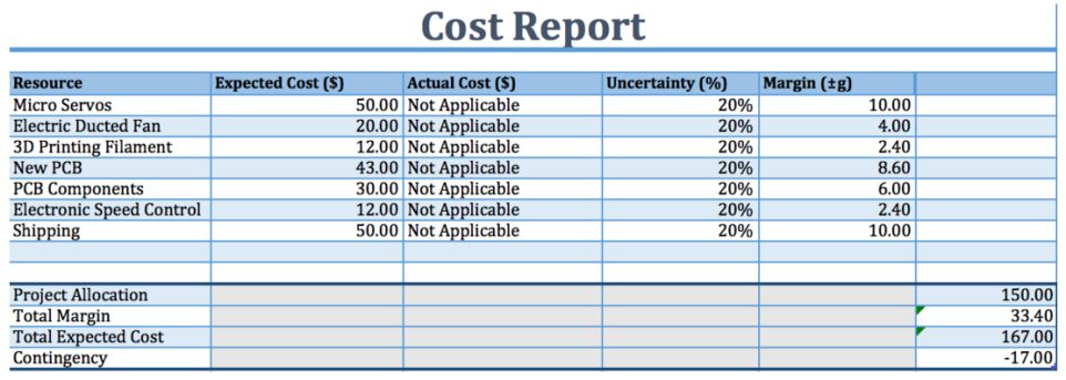
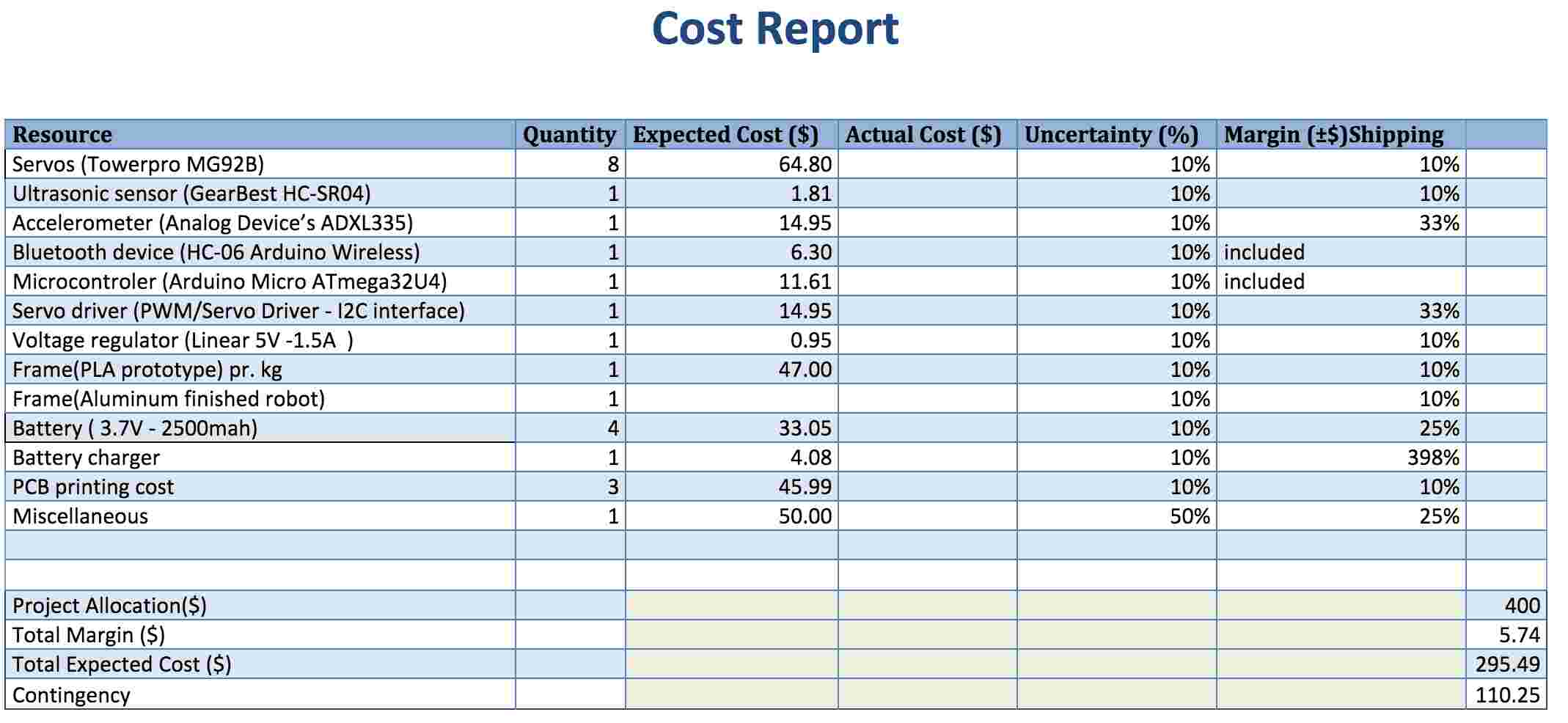
 

Project Budget:

Overview/Purpose: Keep track of budget to avoid overspending.

Budget based on previous semesters:

  • Work with cost estimate as an outline to follow this semester.
  • Preliminary budget based on previous  projects around $400

Mishap: None. Requirements were met by remaining under set budget.

Proposed solution(s) for Spring 2016:

  • Create spreadsheet that keeps track of budget for all vendors and components of the vehicle.
  • Weekly update main spreadsheet with all procurement details.
  • Emphasize consistent documentation format to make information easy to access during the semester.
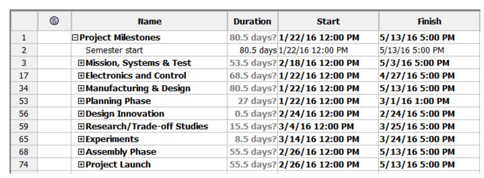
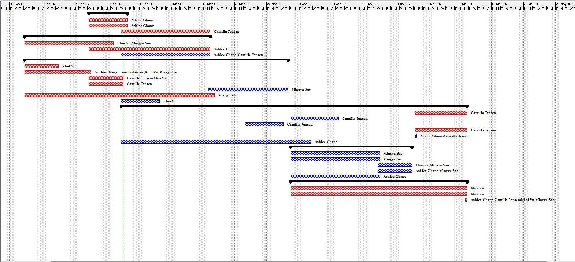
 

Project Schedule:

Overview/Purpose: Set a work schedule to follow on a weekly basis throughout the semester..

Project schedule based on previous semesters.

  • Use level 1/2 requirements to establish appropriate schedule .
  • Keep track of time invested each week for all members.
  • Include status and completion for each member.

Proposed solution(s) for Spring 2016:

  • Document progress every time an action item is closed.


EVALUATION RUBRIC

  1. Is the requirement, Quantitative, Verifiable, and Realizable?
  2. Is the requirement located at the correct level (1 – program / Project)
  3. Is the requirement response to a higher level requirement or customer’s objective (Requirement Flow Down)? Is the linkage clearly defined?
  4. Does requirement provide links to source material?
  5. Does the requirement move the design process forward?
  6. Are equations used to calculate a requirement provided and are answers correct?
  7. The requirements that are missing are the hardest to discover and will be factored into your evaluation.
  8. Is language in the form of a requirement?
  9. Avoid multiple requirements within a paragraph (i.e., breakup statements that contain multiple requirements.)

Y= Yes

N= No

X= No answer needed

Level 1 Requirements based from previous semesters 1 2 3 4 5 6 7 8 9
Must complete the project before end of semester. Y Y N Y N N X Y X
Will follow regulations and policies for the FAA, UAS, & COE. Y Y Y Y N N X Y X
Must not exceed budget. (estimated $400 from last semester) Y Y N N N Y X Y X
Aircraft will maintain stable altitude while completing course. Y Y Y Y Y N X Y X
Remote control aircraft and display light show. Y Y Y N N N X N X
Meet aesthetic requirement set by the customer. Y Y N N Y N X Y X

Works cited:


  1. Arechiga, Danny. “Level 1 Requirements.” Arxterra. N.p., 16 Sept. 2015. Web. 11 Feb. 2016. <https://www.arxterra.com/level-1-requirements-4/>.
  2. Hatori, Ayaka. “Arxterra | Mission Objective and Level 1 Requirements.” Arxterra. N.p., 18 Mar. 2015. Web. 11 Feb. 2016. <https://www.arxterra.com/mission-objective-and-level-1-requirements/>.
  3. Hatori, Ayaka. “Final Documentation.” Arxterra. N.p., 13 May 2015. Web. 11 Feb. 2016. <https://www.arxterra.com/final-documentation-3/>
  4. Hatori, Ayaka. “Arxterra | Final Documentation.” Arxterra. N.p., 13 May 2015. Web. 11 Feb. 2016. <https://www.arxterra.com/executive-summary-final-project-documentation/>
  5. Hatori, Ayaka. “Mission Objective and Level 1 Requirements.” Arxterra. N.p., 8 Mar. 2015. Web. 11 Feb. 2016. <https://www.arxterra.com/ufo-intro/>.
  6. Mohideen, Shamir. “UFO Final Documentation.” Arxterra. N.p., 14 Dec. 2014. Web. 11 Feb. 2016. <https://www.arxterra.com/ufo-final-documentation/>.
  7. Mohideen, Shamir. “UFO Preliminary Project Documentation.” Arxterra. N.p., 28 Oct. 2014. Web. 11 Feb. 2016. <https://www.arxterra.com/ufopreliminary-project-documentation/>.
  8. Vo, Tuan, and Elaine Doan. “Level 1 Requirements.” Arxterra. N.p., 21 Apr. 2014. Web. 11 Feb. 2016. <https://www.arxterra.com/level-1-requirements/>.
  9. Teng, James. “UFO Preliminary Project Plan.” Arxterra. N.p., 30 Sept. 2015. Web. 11 Feb. 2016. <https://www.arxterra.com/ufo-preliminary-project-plan/>.
  10. Hatori, Ayaka. “Arxterra | Final Documentation.” Arxterra. N.p., 13 May 2015. Web. 11 Feb. 2016. <https://www.arxterra.com/executive-summary-final-project-documentation/>.
  11. Stapleton, Anne. “Final Project Progress Report.” Arxterra. N.p., 19 Dec. 2013. Web. 11 Feb. 2016. <https://www.arxterra.com/project-progress-report/>.
  12. Mohideen, Shamir. “Schedule.” Arxterra. N.p., 14 Dec. 2014. Web. 11 Feb. 2016. <https://www.arxterra.com/schedule/>.
  13. Teng, James. “UFO Project Summary.” Arxterra. N.p., 17 Dec. 2015. Web. 11 Feb. 2016. <https://www.arxterra.com/ufo-project-summary/>.


2. Mission, Systems and Testing Research:

LEVEL 2 REQUIREMENTS:

Overview/Purpose: Detail level 2 requirements in alignments with level 1 requirements made to complete mission


Level 2 Requirements from previous semesters:

  • Quadcopter frame and electric ducted fans
  • specify UFO diameter and weight
  • Fire protection
  • LED ring for light show
  • Use of Electronic Speed Controllers (ESCs)
  • Control system consisting of microcontroller and flight controller
  • wireless communication via phone application and bluetooth module
  • Landing gear equipment
  • Shell mold for UFO appearance
  • Achieve flight and specify elevation and flight speed
  • Provide sufficient power for classroom flight


Mishaps: Stable flight has yet to be achieved with certain requirements never initiated (landing gear, flight, fire protection,…)
Proposed Spring 2016 Solution: revise level 2 requirements and consider new ones if new level 1 requirements are made

DIGITAL SIGNAL CANCELLATION:

Overview/Purpose: Implementation of signal cancellation from a digital approach, specifically by inverting the signal


Digital Signal Cancellation from previous semesters:

  • Via Simulink, simple cancellation made via inverting signal (sine wave used)
  • Via audio recording, cancellation attempted by simultaneously playing sounds of original signal and inverted signal (guidance with matlab code)


Mishaps: Cancellation failed via audio recordings
Proposed Spring 2016 Solution: Discuss with team if further work is necessary; If approved look into researching noise cancellation for aircrafts

NEOPIXEL LED LIGHT SHOW:

Overview/Purpose: A lightshow on the Adafruit NeoPixel Ring controlled with a microcontroller, bluetooth module, and app


NeoPixel LED Light Show from previous semesters:

  • LED control circuit w/o bluetooth to test custom light shows
  • LED control w/ bluetooth module via bluetooth terminal app
  • Light show integration with arxterra code
  • Created function/code from scratch for programming lightshow


Mishaps: None; successful creation of programmable LED light show; tape lights considered and never revisited
Proposed Spring 2016 Solution: Consider investigation light functions to display battery life

BLUETOOTH INTERFACE TO ARXTERRA APPLICATION:

Overview/Purpose: how to use bluetooth to control the UFO via phone


Bluetooth Interface from previous semesters:

  • step-by-step procedure on testing a bluetooth module with simple LED example
  • via phone application and Multiwii controller, the UFO can be controlled wirelessly


Mishaps: None; successful bluetooth integration
Proposed Spring 2016 Solution: Consider using, editing, or remaking method of controlling the UFO

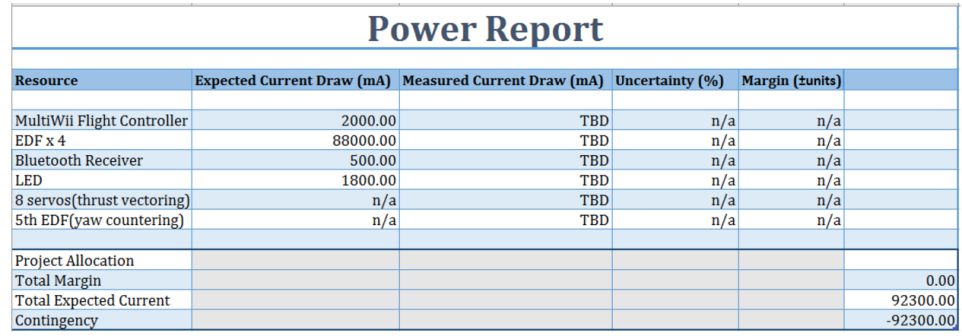
ESC CURRENT DRAW TEST:

Overview/Purpose: Calculations of current draw from EDFs for overall power consideration


ESC Current Draw Test from previous semesters:

  • Completed testing and tabled results


Mishaps: Upon shorting, an upgrade was made to replace the ESC for short time to maximum throttle
Proposed Spring 2016 Solution: Consider retesting to check for functionality

EDFs (ELECTRIC DUCTED FANS):

Overview/Purpose: Overview on Electric Ducted Fans (EDFs) bought and installed on the UFO.


EDFs work from previous semesters:

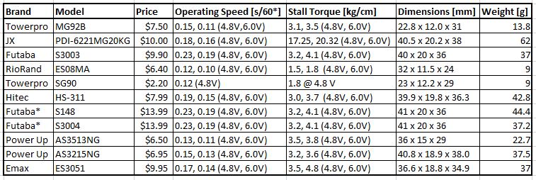
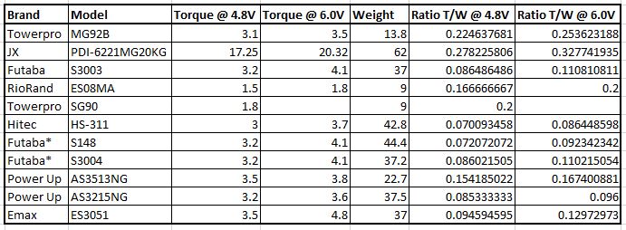
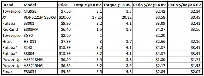
  • Specifications provided: Dr. Mad 50mm 10 blade EDFs
  • Calculation of thrust outputs at various throttle levels for each EDF
    • Completed testing and tabled results
    • not perfectly linear
  • estimated weight: 1100g; 1100g thrust =  60%-70%; conclusion: stable flight = > 70% throttle
  • Cancelling horizontal torque of EDFs
    • New Fans: too costly and couldn’t find one to fit UFO model
    • Fan Tilt: tilt for counter clockwise thrust; concluded tilt will prevent spinning
    • Air Ducts: implement louvers to redirect airflow
  • Testing done on best number of blades
  • Solidworks simulation done to see if air ducts will minimize rotation in same direction


Mishaps:

  • Calculations of blade positioning seem incorrect
  • Cancelling of horizontal torque failed
  • Testing number of blades only considered three and ten blades
  • Air duct testing did not resolve unwanted rotation

Proposed Spring 2016 Solution: Retake tests and specifications

WIRELESS REMOTE COMMUNICATION USING XBEE RADIOS:

Overview/Purpose: wireless communication between the UFO and the user via an XBee Radio


Wireless Remote Communications from previous semesters:

  • controller: joysticks controlling vertical and horizontal via potentiometers
  • XBee: configuration, data, interpretation
  • vertical testing: joystick up increased fans accordingly


Proposed Spring 2016 Solution:

  • Consider getting new EDFs

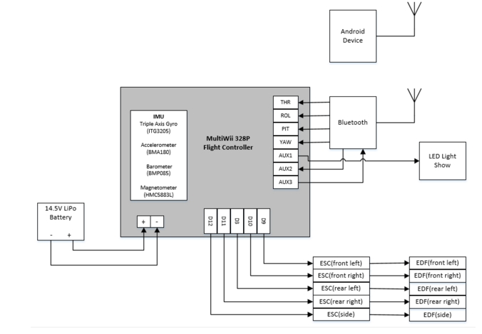
UFO SYSTEM BLOCK DIAGRAM AND ELECTRICAL SCHEMATIC:

Overview/Purpose: Provided system block diagram and electrical interface diagram of UFO


System Block Diagram and Electrical Schematics from previous semesters:

  • outlines system block diagram
  • corresponding wiring diagram for system block diagram outlined


Mishaps: upon visual inspection, there is room for improvement
Proposed Spring 2016 Solution: Update with any changes made this semester

EVALUATION RUBRIC

  1. Is the requirement, Quantitative, Verifiable, and Realizable?
  2. Is the requirement located at the correct level (1 – program / Project)
  3. Is the requirement response to a higher level requirement or customer’s objective (Requirement Flow Down)? Is the linkage clearly defined?
  4. Does requirement provide links to source material?
  5. Does the requirement move the design process forward?
  6. Are equations used to calculate a requirement provided and are answers correct?
  7. The requirements that are missing are the hardest to discover and will be factored into your evaluation.
  8. Is language in the form of a requirement?
  9. Avoid multiple requirements within a paragraph (i.e., breakup statements that contain multiple requirements.)

Y= Yes

N= No

X= No answer needed

Level 2 Requirements based from previous semesters 1 2 3 4 5 6 7 8 9
UFO will be created with quadcopter frame and electric ducted fans Y Y Y N Y N X Y X
UFO will have specific diameter and weight Y Y N N N N X Y X
UFO will be protected against fires N Y Y Y Y N X Y X
UFO will utilize LED ring for light show Y Y Y N Y Y X Y X
UFO will use Electronic Speed Controllers (ESC) Y Y Y N Y N X Y X
UFO will use a microcontroller and flight controller as control system Y Y Y N Y N X Y X
UFO will be able to communicate wirelessly via Arxterra application and bluetooth module with specific range Y Y Y N Y N X Y X
UFO will be equipped with landing gear Y Y Y N Y N X Y X
UFO will have shell to give likeliness to UFO Y Y Y N Y N X Y X
UFO to achieve flight with specific elevation and speed Y Y Y Y Y N X N X
UFO to provide enough power for flight around classroom Y Y Y Y Y N X N X


Works cited:

  1. Hatori, Aya. “UFO Level 2 Requirements.” Arxterra. N.p., 4 Apr. 2015. Web. 11 Feb. 2016. <https://www.arxterra.com/ufo-level-2-requirements/>.
  2. Vo, Tuan, and Elaine Doan. “Level 2 Requirements.” Arxterra. N.p., 21 Apr. 2014. Web. 11 Feb. 2016. <https://www.arxterra.com/level-2-requirements-2/>.
  3. Nunez, Marco. “Digital Signal Cancellation.” Arxterra. N.p., 23 Nov. 2015. Web. 10 Feb. 2016. <https://www.arxterra.com/digital-signal-cancellation/>.
  4. Nunez, Marco. “Custom Programmable LED Light Shows.” Arxterra. N.p., 14 Nov. 2015. Web. 11 Feb. 2016. <https://www.arxterra.com/custom-programmable-led-light-shows/>.
  5. Nunez, Marco. “Creating NeoPixel Ring Lightshow.” Arxterra. N.p., 8 Nov. 2015. Web. 11 Feb. 2016. <https://www.arxterra.com/creating-neopixel-ring-lightshow/>.
  6. Webster, Logan. “How To: Light Show!” Arxterra. N.p., 20 Apr. 2015. Web. 11 Feb. 2016. <https://www.arxterra.com/how-to-light-show/>.
  7. Mohideen, Shamir. “LED Tape Lights for the UFO.” Arxterra. N.p., 13 Dec. 2014. Web. 11 Feb. 2016. <https://www.arxterra.com/led-tape-lights-for-the-ufo/>.
  8. Nunez, Marco. “Learning To Use a Bluetooth Module.” Arxterra. N.p., 20 Oct. 2015. Web. 11 Feb. 2016. <https://www.arxterra.com/learning-to-use-a-bluetooth-module/>.
  9. Alhammadi, Ahmed. “Bluetooth Interface to Arxterra Application.” Arxterra. N.p., 8 Apr. 2015. Web. 11 Feb. 2016. <https://www.arxterra.com/bluetooth-interface-to-arxterra-application-in-progress/>.
  10. Winter, Nathan. “ESC Current Draw Test.” Arxterra. N.p., 13 Dec. 2014. Web. 11 Feb. 2016. <https://www.arxterra.com/esc-current-draw-test/>.
  11. Winter, Nathan. “Electric Ducted Fans.” Arxterra. N.p., 13 Dec. 2014. Web. 11 Feb. 2016. <https://www.arxterra.com/electric-ducted-fans/>.
  12. Winter, Nathan. “Dr. Mad 50 Mm 10 Blade EDFs.” Arxterra. N.p., 13 Dec. 2014. Web. 11 Feb. 2016. <https://www.arxterra.com/dr-mad-50-mm-10-blade-edfs/>.
  13. Winter, Nathan. “EDF Thrust Test.” Arxterra. N.p., 13 Dec. 2014. Web. 11 Feb. 2016. <https://www.arxterra.com/edf-thrust-test/>.
  14. Winter, Nathan. “Cancelling the Horizontal Torque Produced by EDFs.” Arxterra. N.p., 25 Nov. 2014. Web. 11 Feb. 2016. <https://www.arxterra.com/cancelling-the-horizontal-torque-produced-by-edfs/>.
  15. Hatori, Ayaka. “Electric Ducted Fans – Number of Blades TOS.” Arxterra. N.p., 6 Mar. 2015. Web. 11 Feb. 2016. <https://www.arxterra.com/electric-ducted-fans-number-of-blades-tos/>.
  16. Montano, Juan. “Implementing the Air Ducts.” Arxterra. N.p., 20 May 2014. Web. 11 Feb. 2016. <https://www.arxterra.com/implementing-the-air-ducts/>.
  17. Rice, Jake. “Wireless Remote Communication Using XBee Radios.” Arxterra. N.p., 20 Mar. 2014. Web. 11 Feb. 2016. <https://www.arxterra.com/wireless-remote-communication-using-xbee-radios/>.
  18. Stapleton, Anne. “System Block Diagram & Electrical Schematic.” Arxterra. N.p., 2 Dec. 2013. Web. 11 Feb. 2016. <https://www.arxterra.com/system-block-diagram-electrical-schematic/>.
  19. Ceballos, Salvador. “UFO System Block Diagram and Interface.” Arxterra. N.p., 8 Apr. 2015. Web. 11 Feb. 2016. <https://www.arxterra.com/ufo-system-block-diagram-and-interface/>.


3. Design and Manufacturing Research:
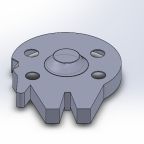
YAW Problem:

Overview/Purpose: The reaction wheels were to be fabricated in order for fix the Yaw problem


Research on previous semester work:

  • Group decided to make reaction wheels to solve the yaw problem.
  • Group decided that a cylinder design would work and that they should spin opposite of fans.
  • Determined that heavier material would produce more torque.
  • Group agreed to to use ABS plastic since it was the easiest to fabricate using a 3D printer
  • Fritzing diagram was developed
  • After receiving recommendations from the class president, the reaction wheels idea was scrapped and the group agreed to tilt the angle of thrust of the fans in order to mimic a quadcopter and fix the yaw problem.
  • Group decided to test if more blades on fan gave more thrust. They tested  3 blade fans vs 10 blade fans. They came to the conclusion that the 10 blade fan produced more thrust but ended up using a 5 blade fan because they did not have enough of the 10 blade fan to use.
  • From the previous semester it seems that the motor mounts required taping of the motors and to avoid this they had planned to use an acrylic block.
  • Solidworks was used to determine the airflow of the fans
  • Based on these simulations, it was determined that the air flows like an upside down whirlwind which would turn into a problem if they have another fan spinning the same direction. The airflow of two fans made the airflow go upward instead of straight down.
  • To fix this, the group decided to use an air duct to stabilize it. It seems like they still had a problem with the yaw and to fix this, they repositioned the air duct.

Mishaps

Proposed Solution for Spring 2016:

  • In order to speed up the process, we will be looking into changing the fans and will be performing different tests to see which fans work better. We may possibly get more fans or change the rotation of the fans.

UFO’s shell production:

Overview/Purpose: The purpose of the shell was to give the UFO a look that resembled the craft from the movie “ The day the Earth stood still”

Research on previous semester work:

  • Manufacturing Engineer worked with a Design Engineer to make the UFO Shell molding
  • 14 24x4x1 pieces of foam were glued together to make a piece big enough to make the mold.
  • Holes were then cut, though the group did not state how they determined the size and position of the holes and then painted the shell glossy gray.   
  • Group talked about mounting on a frame or shell and they agreed that frame mounting was better since it was cleaner and lighter and easier to work with.
  • They then researched the materials to construct the shell ( styrene or carbon fiber shell). They agreed to use Styrene since it was lighter and cheaper
  • A negative of the shell was created to be used on the UFO
  • Next they decided to vacuum form mold a shell. They had a shell from the previous semester and they were able to use it for the vacuum form molding. It proved to be a much better but they still had some issues  such as having a hole in the shell.
  • Their manufacturing Engineer made urethane foam mold on the lathe machine in the design lab. She did this by one inch by 1.5 inch of layers together with spray adhesives and waiting for them to bond. Next the holes for each motor were determined and done by using a 55mm drill press.
  • Next they used the plastic molding machine. Eight forms were made with each attempt adjustments were made to the mold. The shell was then painted silver.

Mishaps

  • They soon discovered that the lathe machine used to make the dome shape was 6 inches and would only provide 12 inches diameter. The shell diameter needed to be 15 inches.  To fix this, they cut the foam in half in order to make them separately then glue them back together. Two shells were made, one that was ⅛ of an inch and the other 1/16 an inch. After vacuuming the shell, the ⅛ ended up being too thick for the UFO so the group decided to stick to the 1/16 shell. (Fall 2015)
  • At first attempts the mold was left in high temperatures and became disfigured.(Spring 2015)
  • Apparently they attempted to removed the material from the lathe but it failed since they removed too much material. They had to remake the mold. (Spring 2015)
  • The group attempted to print out the ufo and then piece it together. Due of time constraints they were not able to get the mold right. They only got the prototype one and was considered to be 20 percent done.

Proposed Solution for Spring 2016:

  • We will model out our mold to look like the millenium falcon. Using the same techniques that previous semesters did, we will be making a mold for it but instead of making separate pieces to make it look like the ufo from “ The day the earth stood still”, we will be making different pieces to make it look like the Millenium falcon. We may end up making the bigger round piece the same way last semester did it, with the adjustments of the fans then bond on the additional pieces to make it look like the Millennium falcon. We will take precautions in order to not make the same mistakes from last semester such as speeding up the process using the lathe machine by taking the right dimensions and also not burning out the mold.

UFO’s PCB:

Overview/Purpose: To create a PCB and a surface mount device used to control the UFO and LED light show.


Research on previous semester work:

  • Group got rid of bundle of wires used to distribute the power to the ECS and LED’s
  • Labeling was added to the EagleCAD schematic so that everyone knew which part was which.
  • Copper pad was added around the board
  • Group decided to build a separate custom PCB for the battery protection of the circuit since the lithium polymer did not include a built in protection circuit.
  • They followed a protection circuit that was created by DIY Perks. They incorporated what they learned to their PCB and they combined the components required to protect the light show as well to the PCB.
  • Once silicon was applied to the carbon fiber mold, it took about 18 hours for it to cure.

Mishaps

  • When assembling the PCB the potentiometer was connected incorrectly but was quickly fixed. (Spring 2015)
  • The group wanted to have the Multiwii on top of the PCB with space in between but they did not have enough clearance to connect the Bluetooth module on top of the PCB. To fix this they used 90 degree male headers and then connected to the bluetooth module from the outside. (Spring 2015)
  • The group was missing a crystal oscillator. To fix this, they took another one and soldered it to the PCB. Test code worked but the custom code did not work, perhaps because the bluetooth module was syncing to the board properly. (Spring 2015)
  • Lastly they did not give the PCB enough space to distribute all current required to power the UFO. Connectors also broke while assembling it but they used wires to fix it.(Spring 2015)

Proposed Solution for Spring 2016: This semester, we will be ensuring that the PCB has enough space to make sure that current flows through smoothly. We will also be working on Soldering on the components properly. One thing that was notices was that some wires were not soldered on properly, therefore breaking off and possibly not making a proper connection.  We will also be insulating out wire components in order to not have a bundle of wires nested around.
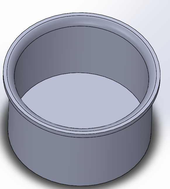
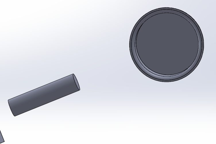
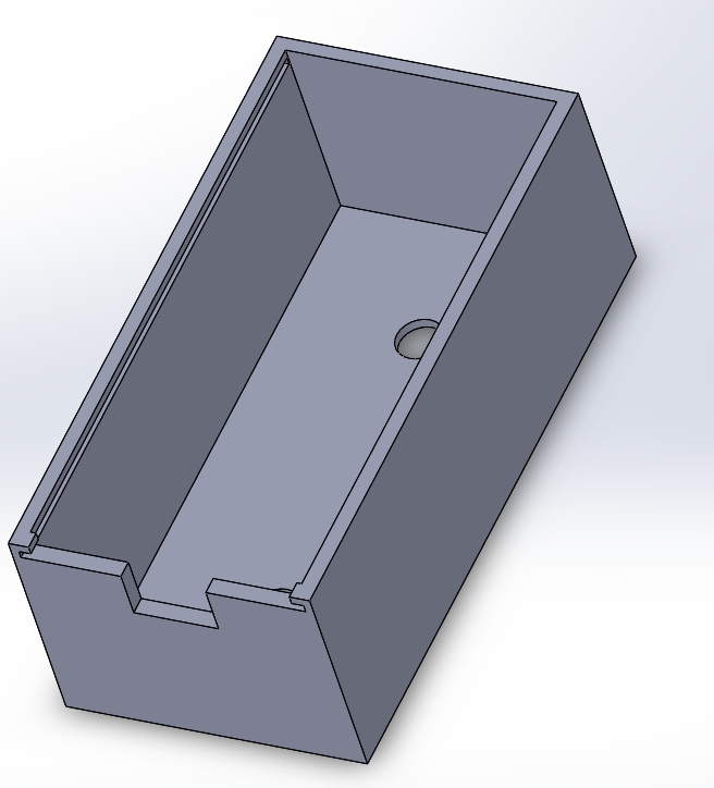
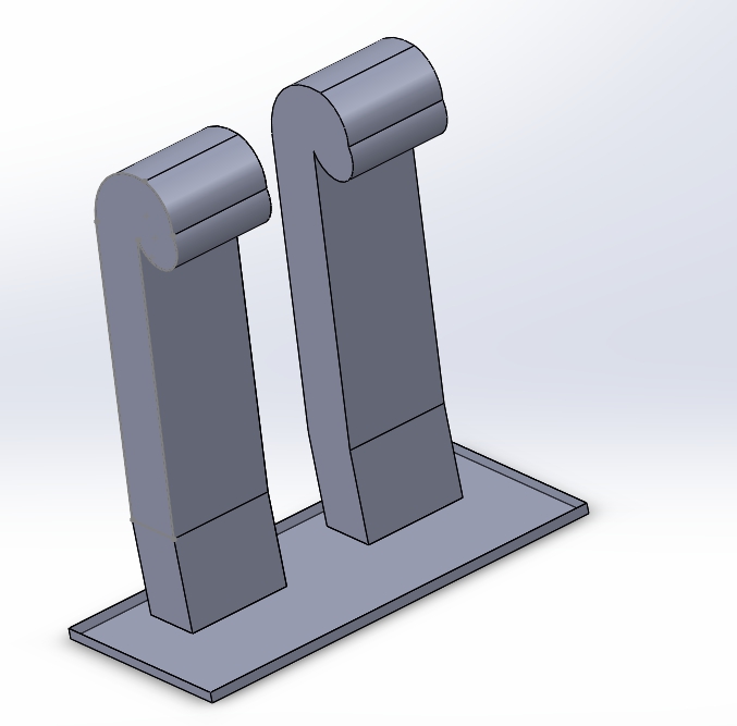
 

Carbon Fiber Body:

Overview/Purpose: To build a carbon fiber body for the UFO using the design from the previous semester.


Research on previous semester work:

  • A silicon mold was made from the original 3D printed body and then the carbon fiber pieces were made from the mold.
  • A quarter of a mold was made since it is very expensive to make. apparently it is 25$ for two bottles.
  • 3D printed parts needed to be sanded down since undesired grooves were made while being printed.

Mishaps

Proposed Solution for Spring 2016: Not much modifications will be done to the carbon fiber body. The only improvement we are proposing is to add on a case for the battery since it is unprotected at the moment and want to protect it from getting damaged. Along with making a case we want to add on landing legs to it so the UFO will land safely instead of landing on the battery itself.

  1. Teng, James. “UFO Project Summary.” Arxterra. N.p., n.d. Web. 11 Feb. 2016. <https://www.arxterra.com/ufo-project-summary/>.
  2. Teng, James. “Reaction Wheel Research.” Arxterra. N.p., 26 Oct. 2015. Web. 11 Feb. 2016. <https://www.arxterra.com/reaction-wheel-research/>.
  3. Teng, James. “Reaction Wheel Material Trade-off Studies.” Arxterra. N.p., 29 Oct. 2015. Web. 11 Feb. 2016. <https://www.arxterra.com/reaction-wheel-material-trade-off-studies/>.
  4. Hatori, Ayaka. “Final Documentation.” Arxterra. N.p., 13 May 2015. Web. 11 Feb. 2016. <https://www.arxterra.com/final-documentation-3/>.
  5. Hatori, Ayaka. “Electric Ducted Fans – Number of Blades TOS.” Arxterra. N.p., 6 May 2015. Web. 11 Feb. 2016. <https://www.arxterra.com/electric-ducted-fans-number-of-blades-tos/>.
  6. Montano, Juan. “Implementing the Air Ducts.” Arxterra. N.p., 20 May 2014. Web. 12 Feb. 2016. <https://www.arxterra.com/implementing-the-air-ducts/>.
  7. Montano, Juan. “Determining the Number of Fans.” Arxterra. N.p., 16 Mar. 2014. Web. 12 Feb. 2016. <https://www.arxterra.com/determining-the-number-of-fans/>.
  8. Huynh, Tien-Phuc. “UFO Shell’s Production.” Arxterra. N.p., 6 Dec. 2015. Web. 12 Feb. 2016. <https://www.arxterra.com/ufo-shells-production/>.
  9. Sakurai, Catherine. “UFO Shell Trade off Studies.” Arxterra. N.p., 15 Apr. 2015. Web. 12 Feb. 2016. <https://www.arxterra.com/ufo-shell-trade-off-studies/>.
  10. Hatori, Ayaka. “Shell Molding.” Arxterra. N.p., 6 May 2015. Web. 12 Feb. 2016. <https://www.arxterra.com/shell-molding/>.
  11. Hatori, Ayaka. “Completed Project with Progress Update.” Arxterra. N.p., 13 May 2015. Web. 12 Feb. 2016. <https://www.arxterra.com/completed-project-with-progress-update/>.
  12. Vo, Tuan. “Building the UFO 1.02 (Code Name: George Michael).” Arxterra. N.p., 20 May 2014. Web. 12 Feb. 2016. <https://www.arxterra.com/building-the-ufo-1-02-code-name-george-michael/>.
  13. Huynh, Tien-Phuc. N.p., 16 Dec. 2015. Web. 11 Feb. 2016. <https://www.arxterra.com/ufos-printed-circuit-board/>.
  14. Hatori, Ayaka. N.p., 13 May 2015. Web. 11 Feb. 2016. <https://www.arxterra.com/pcb-design-battery-protection-circuit/>.
  15. Winter, Nathan. “Manufacture the Carbon Fiber Body.” Arxterra. N.p., 25 Nov. 2014. Web. 12 Feb. 2016. <https://www.arxterra.com/manufacture-the-carbon-fiber-body/>.


4. Electronics and Controls Research:

YAW Control:

Overview/Purpose: Prevent UFO from spinning uncontrollably by stabilizing the yaw rotation.  


Yaw Control from previous semester:

  • 3 Possible Ideas:
    • Reaction Wheel spins in opposite direction to cancel out yaw rotation.
    • Attach a 5th fan on the side to counter the rotation caused by the other 4 fans
    • Tilt fans.


Mishaps:

  • Several experiments show that the reaction wheel would not work.
  • A 5th fan on the side would disturb the symmetry of the UFO and cause additional problems.

Proposed Solution for Spring 2016:

  • Tilting the EDFs is the easiest way to cancel out the yaw rotation. More experiments will be needed to determine the angles best suited for our UFO.

PID Tuning:

Overview/Purpose: Determine the best coefficient values for our PID controller so that we would achieve the most efficient stabilizing effect.


PID tuning from Previous Semester:

  • Used “EZ-GUI Ground Station” app to find P,I,D gains.
  • Strapped UFO to inverted chair for safety and easy tuning process.


Mishaps:

  • none


Proposed Solution for Spring 2016:

  • Discuss with team if further work is agreed upon.
  • Possibly incorporate other types of controller designs besides PID for more efficiency. ex.LQR

Analog Noise Cancellation:

Overview/Purpose: Use analog components to design a noise cancelling circuit to reduce the noise of the UFO.


Analog Noise Cancellation from Previous Semester:

  • Designed a noise cancelling circuit.
  • The circuit receives the input signal through a microphone.
  • Input signal is sent through a non-inverting amplifier to boost the voltage to workable levels.
  • The boosted signal is then sent through an inverting amplifier to shift it 180 degrees.
  • After amplifying and inverting the signal, it is sent to a speaker to produce noise.


Mishaps:

  • Theoretically, when this output noise is played alongside the input noise, the 2 should cancel each other out. It did not work as expected.
  • The input noise and the output noise must precisely synchronize in order to cancel out each other. This proved too difficult to achieve.


Proposed Solution for Spring 2016:

  • Discuss with team if further work is agreed upon.

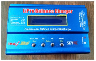
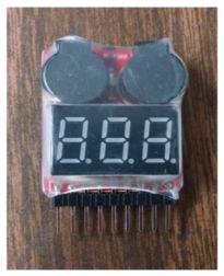
Experiment: Battery Discharge Characteristics and Voltage Monitor:


Overview/Purpose:

  • Determine how long battery will last while UFO is running at 80% throttle.


Battery Discharge Characteristics and Voltage Monitor from previous Semester:

  • Test circuit was designed to read the voltage levels of each cell within the battery.
  • The UFO was then connected to the circuit and turned on at 80% throttle while the voltage levels were being monitored.
  • Data shows that the battery cells reached undesired levels at around 10 minutes.
  • Voltage reader was then constructed as a warning indicator of low battery levels.


Mishaps:

  • none.

Proposed Solution for Spring 2016:

  • Discuss with team if further work is agreed upon.
  • Possibly design a safety landing feature, where the UFO will shut off all wireless communication with the remote controller and automatically land when the battery levels are low.

Multiwii ESC and Receiver Connections:


Overview/Purpose:

  • Documentation on how to connect the ESC and receiver to the microcontroller.


Multiwii ESC and Receiver Connections from previous Semester:

  • Instructional post on which connectors go into which pins of the microcontroller.


Mishaps:

  • none.


Proposed Solution for Spring 2016:

  • This post will be used as a guideline when installing our ESC’s and receiver.

PCB Design – Battery Protection Circuit:


Overview/Purpose:

  • Instructional video on creating a Battery Protection Circuit to prevent over-discharging.


Battery Protection Circuit from previous Semester:

  • The LiPo battery in our possession does not have a Protection Circuit.
  • Design of a Battery Protection Circuit shall be included in the PCB.


Mishaps:

  • none


Proposed Solution for Spring 2016:

  • This post will be used as a guideline to include a Battery Protection Circuit in our own PCB.
  • Possibly add a feature to safely land at low battery levels to prevent UFO from crash landing when the battery shuts off.

PID Control and Tuning:


Overview/Purpose:

  • Informative Post on PID Control


PID Control and Tuning from previous Semester:

  • Detailed instructions on how to PID tune.
  • Links included for PID controller download for Arduino IDE.
  • Instructions on altering files to be compatible with UFO.

Mishaps:

  • none


Proposed Solution for Spring 2016:

  • similar set up will be used for PID tuning.

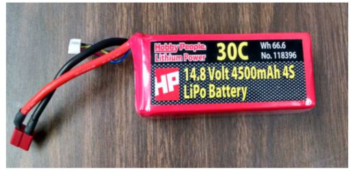
Trade-Off Study: Battery


Overview/Purpose:

  • Comparison of different types of batteries to determine best battery for UFO.


Battery Trade-Offs from previous Semester:

  • Used same trade-off study from Spring 2014
  • Turnigy nano-tech A-Spec G2 met all required specifications.

Mishaps:

  • none


Proposed Solution for Spring 2016:

  • Create updated chart with more options.

Quadcopter PID Control:


Overview/Purpose:

  • Informative post on PID control.

PID Control from previous Semester:

  • A PID controller measures the error between the actual and desired values.
  • It then makes corrections to the system to reduce the error and make the actual value as close to the desired value as possible.
  • The speed and efficiency of the correction is heavily dependant upon the P, I, and D coefficients of the controller.
  • Lists of pro and cons of each coefficient is shown in the post.


Mishaps:

  • none.


Proposed Solution for Spring 2016:

  • very informative post on PID control.
  • will use for future reference.

Trade-Off Study: Motor Battery Selection


Overview/Purpose:


  • Comparison of different types of batteries to determine best battery for UFO.


Battery Trade-Offs from previous Semester:


  • Study was done comparing cost, weight, capacity, max discharge rate, max current draw, max flight time, and capacity/weight ratio.


  • MaxAmps LiPo was chosen due to the high capacity and cost advantage, as well as the higher current draw than any other options.


Mishaps:

  • none


Proposed Solution for Spring 2016:


  • Create updated chart with more options.

Final Controls Update:


Overview/Purpose:

  • Detailed results of Fall 2013 quadcopter. Recommendations for future UFO project members.


Final Controls Update from previous Semester:

  • future recommendations:
    • tune PID more accurately
    • prevent yaw rotation
    • tinyduino is hard, use a different microcontroller if possible
      • EDFs provide more thrust than anticipated, so the UFO can support a heavier microcontroller if needed
      • breakout board on tinyduino is 1mm, extremely hard to work with.


Mishaps:

  • PID needs better tuning to improve stabilization during hover and turn operations.
  • yaw rotation out of control. design something to counter it.
  • tinyduino is not easy to work with.


Proposed Solution for Spring 2016:

  • research more on PID tuning.
  • research angle tilt of fans to counter yaw rotation.
  • new microcontroller if budget allows.

Experiment: Prototype Test


Overview/Purpose:

  • Conducted tests to determine whether quadcopter meets requirements and whether updates need to be made to the design.


Prototype Test from previous Semester:

  • 3 Tests: Rotation, Lift, Tilt
    • Test A(Rotation) results:  it is noted that the yaw rotation is caused by an increase in acceleration. if the velocity of the fans is slowly increased the rotation will be reduced.
    • Test B(Lift) results: around 36% applied thrust is required to lift the UFO and maintain hover.
    • Test C(Tilt) results: tilting the UFO succeeded but the tilt may not be enough for it to turn in the desired direction.


  1. Arechiga, Danny. “YAW Control.” Arxterra. N.p., 12 Dec. 2015. Web. 12 Feb. 2016. <https://www.arxterra.com/yaw-control/>.
  2. Arechiga, Danny. “PID Tuning.” Arxterra. N.p., 11 Dec. 2015. Web. 12 Feb. 2016. <https://www.arxterra.com/pid-tuning/>.
  3. Arechiga, Danny. “Analog Noise Cancellation.” Arxterra. N.p., 2 Dec. 2015. Web. 12 Feb. 2016. <https://www.arxterra.com/analog-noise-cancellation/>.
  4. Arechiga, Danny. “Battery Discharge Characteristics and Voltage Monitor.”Arxterra. N.p., 16 Dec. 2015. Web. 12 Feb. 2016. <https://www.arxterra.com/battery-discharge-characteristics-and-voltage-monitor/>.
  5. Arechiga, Danny. “Multiwii ESC and Receiver Connections.” Arxterra. N.p., 26 Oct. 2015. Web. 12 Feb. 2016. <https://www.arxterra.com/multiwii-esc-and-receiver-connections/>.
  6. Hatori, Ayaka. “PCB Design – Battery Protection Circuit.” Arxterra. N.p., 13 May 2015. Web. 12 Feb. 2016. <https://www.arxterra.com/pcb-design-battery-protection-circuit/>.
  7. Ceballos, Salvador. “PID Control and Tuning.” Arxterra. N.p., 22 Apr. 2015. Web. 12 Feb. 2016. <https://www.arxterra.com/pid-control-and-tuning/>.
  8. Jackson, Anthony. “Battery.” Arxterra. N.p., 14 Dec. 2014. Web. 12 Feb. 2016. <https://www.arxterra.com/battery/>.
  9. Mohideen, Shamir. “Quad-copter PID Control.” Arxterra. N.p., 13 Dec. 2014. Web. 12 Feb. 2016. <https://www.arxterra.com/quad-copter-pid-control/>.
  10. Rice, Jake. “Motor Battery Selection.” Arxterra. N.p., 16 Mar. 2014. Web. 12 Feb. 2016. <https://www.arxterra.com/motor-battery-selection/>.
  11. Walth, Carlen. “Final Controls Update.” Arxterra. N.p., 18 Dec. 2013. Web. 12 Feb. 2016. <https://www.arxterra.com/final-controls-update/>.
  12. Walth, Carlen. “Prototype Testing Results.” Arxterra. N.p., 21 Dec. 2013. Web. 12 Feb. 2016. <https://www.arxterra.com/prototype-testing-results/>.


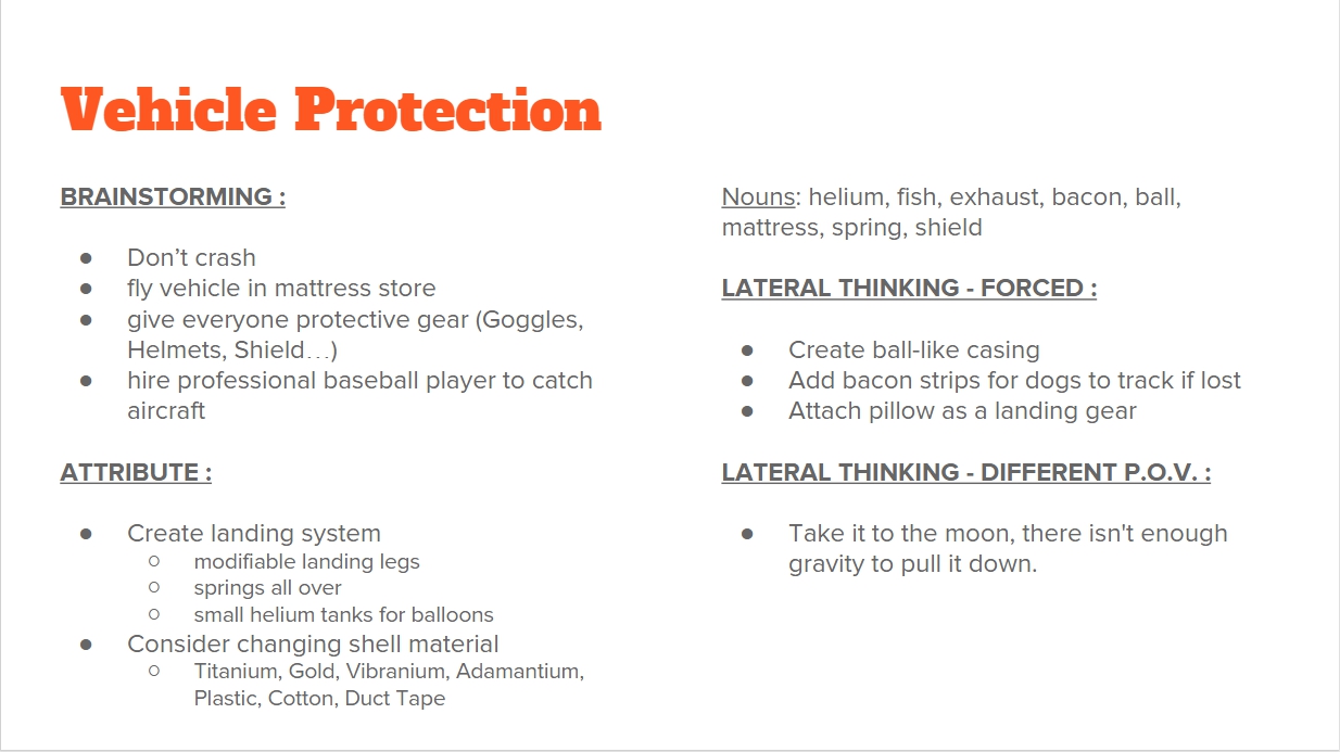
5. Creativity Assignment:

Random Nouns Generated:

  • Mattress
  • Helium
  • Shell
  • Bacon
  • Spring
  • Ball
  • Fish
  • Vehicle
  • Moon
  • Wing
  • Device
  • Mint
  • Kite
  • Wheel

How do we protect vehicle from crash landing damage/ hurting people?

  • Brainstorm
    • don’t crash
    • fly vehicle in mattress store
    • Slow down vehicle as it reaches certain height or battery voltage lowers
    • Give everyone helmets, protective vests, bubble wrap, safety goggles…
    • Hire professional baseball player to catch aircraft
  • Attribute
    • Create landing system
      • Add springs all over (the simpsons maggie)
      • modifiable landing legs
      • Small helium tanks to inflate balloons
    • Shell Material:
      • Titanium
      • Gold
      • Vibranium (Captain America)
      • Adamantium (Wolverine)
      • Plastic
      • Cotton
      • Duct Tape
  • Lateral thinking
    • Forced
    • Random Noun Generator:
      • Helium, Fish, Exhaust, Bacon, Dodge ball, Mattress, Spring, Shield
    • Create new casing to resemble a beach ball/ Dodge ball
    • Fish tail to control the vehicle.
    • Add Bacon strips for dogs (and hungry bacon lovers )to find in case we lose the vehicle
    • Use turtle shell, for battery protection
    • Attach Pillow as a landing gear
  • Different Point of View:
    • Send it to the moon, there isn’t as much gravity like earth to pull it down.

What can we do to control the Yaw rotation?

  • Brainstorm
    • tilt fans
    • alternate clockwise and counterclockwise fans
    • use reaction wheels
    • add wings
    • Have a volunteer counter rotation by hand
  • Attribute
    • heavier shell might be less prone to rotation
      • might reduce yaw rotation
  • Lateral thinking
    • Forced
      • Use coke and mentos propulsion
  • Diff POV
    • Build it in the future, use anti gravity propulsion
    • Fly the device on it’s side; now the yaw problem is a pitch problem
    • Use AI to stabilize itself
    • Build it in the past with no electronics, attach frame to a kite