Fall 2015 MicroBiPed Arxterra Application

ARXTERRA APPLICAIONT & ARDUINO IDE

By Railly Mateo (Systems Engineer)
Approved by Paul Oo (Project Manager)
Approved by Railly Mateo (Systems Engineer)

Configuration:

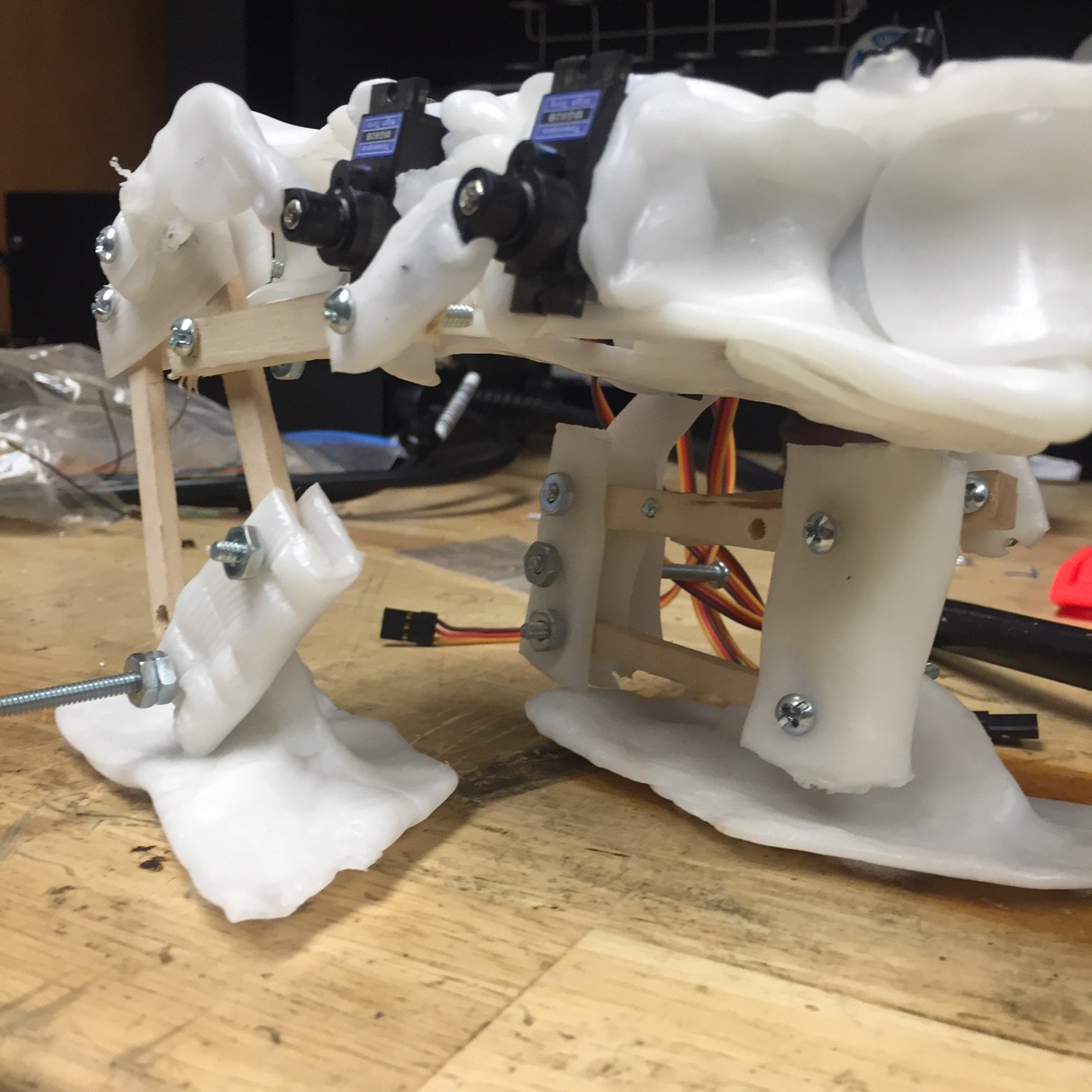
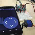
To establish communication between the robot and the phone, its important to know how the Arxterra application works and what kind of information it will send to the microcontroller (Arduino Micro). To interpret what the various telemetry commands were: the Bluetooth device (HC-06) was connected to the Arduino Micro. Next, the arxrobot-firmware was uploaded into the Arduino Micro to establish communication between itself and the Arxterra application (Android version).

Testing Connectivity:

To test connectivity, begin by opening he serial monitor on the Arduino. Play around by pressing on the Arxterra application. When the phone is not connected to the Bluetooth, the monitor will display “emergency exception 0x0100”. When the phone is connected, it will display “robber received command: 11”. When pressing on a direction (forward), five data inputs will be displayed on the monitor. According Hill’s command PDF file, the Arxterra application sends a 7 element matrix to the microcontroller.

Data Interpretation:

Data [0] A5 = Command Packet ID
Data [1] 05 = Packet Length N w/o parity byte
Data [2] 01 = Move ID
Data [3] 01 = Left Motor Forward
Data [4] 80 = Half Speed (128/255)
Data [5] 01 = Right Motor Forward
Data [6] 80 = Half Speed (128/255)
Data [7] A1 = Longitudinal Redundancy Check (LRC)

For our robot, the only elements of interest are data [2], data [3], and data [5]. This is due to our project only using servos, in comparison to using servos and motors. Thus the speed of the robot will only be controlled by using delays in the walking code.

Data [2]: if the command bit is 1, that tells the command decoder to issue a move command.
Data [3] and [5]: These elements are direction bits. If both are set to 1, it is interpreted as forward direction (would mean the reverse direction). However, our servos don’t go in reverse, therefore we won’t be setting these elements to 2.

Setting Up Walking Code:

Begin by pressing on the arrow control panel. Then write down all the telemetry responses that would be needed. By playing with remote functions, you will notice that setting data[3] and [5] to 1 and 1 will be move forward, 1 and 2 will be move to the right, and 2 and 1 will be move to the left.

Walking Command Examples:

If (data3 == 1 && data 5 == 1), the Arduino will read a series of servos angle that will make the walking forward motion.
If ((data3 == 1 && data5 = 2)), the Arduino will read a series of servos angle that will make the right turn.
If ((data3 = 2 && data5 == 1)), the Arduino will read a series of servos angle that will make the left turn.

You can see the implementation of the code in the Prototype blog post.

Fall 2015 MicroBiPed Prototypes

PROTOTPYE MILESTONES

By Railly Mateo (Systems Engineer)
Approved by Paul Oo (Project Manager)
Approved by Railly Mateo (Systems Engineer)

The video above shows the first step taken to understand the mechanics for how our Bipedal robot would walk. This model is considered our 1st Generation (1.0) of BiRex. It is a simply demonstration of a 5-axis leg using MG90S servos to rotate 2 axis, which then cause the rest of the leg to be displaced based on the angles of rotation. The commands used for this demonstration can be found in the Arxterra Application blog post.

This second video shows how we attempted to understand the coding for making our Bipedal robot walk. This model is considered our 2nd Generation (2.0) of BiRex. Although it has integrated 2 5-axis legs onto a body (wooden plank), this model lacked the feet needed to test stability.

This third video shows how we attempted to understand the motion for making our Bipedal robot walk. This model is considered our further developed 2nd Generation (2.5) of BiRex. As you can see, it has difficulty walking. This lack of balance comes from the fact that our legs cannot support overall stability alone, thus verifying the need to add the head and tail.

IMG_1852(1)

Image 1

The image above shows the inclusion of servos for head and tail. However, after showing the progress of our prototype to Professor Hill, he recognized the need to change the design of the leg. This model was unable to lift its leg up, but rather slid to go forward. Because of this detail, we were able to implement a more realistic prototype and find valuable feasibility information.

IMG_1853

Image 2 – 3rd Generation of BiRex

The image above shows the finalized design before moving into producing our last model. Although the plastic molding made the structure too heavy to stay standing, the legs’ rotations resembled human-like walking motion.

Conclusion:
After changing the Mission Profile & Project Objective, we were able to focus our time into learning from trials and errors. This, along with a progressive design innovation, gave us enough data to create proper verification and validation tests.


Fall 2015 Presentation Software

PRESENTATION SOFTWARE TRADE-OFFS

By Paul Oo (Project Manager)
Approved by Railly Mateo (Systems Engineer)
Approved by Paul Oo (Project Manager)

Software Professionalism Visual Appeal Customization User Interface
PowerPoint 9 6.5 8 9
Prezi 7 8.5 8.5 8
PowToon 8 9 9 9

The table above shows the 3 programs used to present our milestones for this project. The numbers assigned to each category per software is on a scale of 1 to 10, with 10 being the highest possible score to receive. The numbers (that I personally assigned) not only reflect user preferences, but our overall grade for each presentation (in exception to PowToon).

When creating the PowerPoint slides for the PDR, Professor Hill noticed the need for stronger visual appeal (hence PowerPoint receiving 6.5 out of 10) . Therefore, I began my trade offs studies for better presentation software. For the CDR, I decided you use Prezi.com. Although the visual appeal, customization, and user interface received good ratings, the longevity (along with the annotative behavior Professor Hill expresses during a CDR presentation) of the presentation made the visuals actually seem bothersome. Finally, PowToon is the software I’ve decided to use for our Final Presentation Video. After using the strictly online software, (Prezi is a downloadable software), I noticed the heavy amount of user-interface information causes the site to lag. That being said, my laptop does not have the best specs.

Fall 2015 MicroBiped Interface Matrix Update

FINALIZED INTERFACE MATRIX & DEFINTIONS

By Railly Mateo (Systems Engineer)
Approved by Paul Oo (Project Manager)
Approved by Railly Mateo (Systems Engineer)

SzTI3jcuUVDzZkg

Table 1

Table 1 above show the 1st portion of project’s updated system interface definitions. The left side of the table has information on our subsystem components, while the right side is simply the microcontroller (Arduino Micro). Each component is then defined by its pinout data (pin number and pin symbol), which is then used as information for the microcontroller’s pinout.

7vtOa7MLNMDapYW

Table 2

Table 2 above show the 2nd portion of project’s updated system interface definitions. Unlike the first table, this section focuses only on our servo interface. The left side of the table has information on the servo driver, while the right side is simply 6 µservos. Because the servo driver has no numbered pins, the table separates each section of the servo driver by its basic connections (PWM, V+, & GND). The µservos are then connected to these connections through their PWM, V+, & GND wires.

A full system block diagram explains how these subsystems structurally connect.
The wiring diagram post explains how we planned to eliminate any possibility of branch-like wiring.


Fall 2015 MicroBiPed System Block Diagram Update

FINALIZED SYSTEM BLOCK DIAGRAM

By Railly Mateo (Systems Engineer)
Approved by Paul Oo (Project Manager)
Approved by Railly Mateo (Systems Engineer)

block diagram(1)

The block diagram above shows the updated block diagram for BiRex. The blocks are positioned based on their subsystem information. This post will give brief descriptions to explain each section of the block diagram.

The top left section comprises of two analog (orientation & distance) sensors. The ultrasonic sensor (HC-SR04) connects to the microcontroller (Arduino Micro) through the PWM & GPIO pins. The gyroscope (ITG-3200) connects the Arduino through its data line (SDA) and clock line (SCL).

The bottom left section comprises of 2 hardware devices (Bluetooth device & Android smartphone) for wireless communication between the Arxterra app and the microcontroller. The bluetooth device (HC-06) connects to the microcontroller through UART pins (RX & TX).

The top right section comprises of components (battery and voltage regulator) for energizing the system. The LiPo battery connects to the voltage regulator to ensure that we do not overload our subsystems. The voltage regulator (LM317) then uses our connections that bridge to the Vin and GND pins on the microcontroller.

Finally the bottom right section mechanical components (servos & servo driver). The servo driver (I2C interface) has two inputs and six outputs. It is energized from the battery and gets commands from the microcontroller through its data and clock lines. Then the signal is outputted to the six µservos (MG92B) allowing BiRex to walk.

Fall 2015 MicroBiPed Battery Update

BATTERY TRADE-OFF UPDATE

By Brian Walton (Manufacturing Engineer)
Approved by Paul Oo (Project Manager)
Approved by Railly Mateo (Systems Engineer)

Item Voltage Amphours Rating Quantity Price Per Qty
Dynamite LiPo Battery DYN 1419 7.4 V 2000 mAh 5C 1 $29.95
Lithium Ion Polymer Battery 3.7 V 2500 mAh 1C 2 $14.95
9V Battery 9V 120-1200mAh 1 $2+

The table above compares 3 possible batteries to use for the µBiPed project. The table compares supplied voltage, Amphours, rating, quantity, and price per quantity. The 3 batteries shown here on the table were chosen based off the updated mass and power reports.

Conclusion:
In the end we went with the Dynamite LiPo battery for multiple reasons:

  1. The price per quantity was negligible between the 7.4 and the 2 3.7 V batteries.
  2. While the 9V battery was cheaper short term, having rechargeable batteries are cheaper long term.
    1. Additionally this project being the feasibility demonstration of a toy, it’ll be better to have the toy already designed for rechargeable batteries.
  3. Even though the Lithium Ion had better rating for Amphours, the Dynamite Pro can handle better surges.

Fall 2015 MicroBiPed Mass Budget

FINALIZED MASS BUDGET

By Michael Balagtas (Manufacturing Engineer)
Approved by Paul Oo (Project Manager)
Approved by Railly Mateo (Systems Engineer)

12209101_1197484403601742_213187105_o

Part Quantity Individual Mass (grams) Total
(grams)
Margins
Servos 6 13.8 82.8 20%
#4 Hex Nuts and Bolts 18 20.7 372.6 10%
Frame 1 857.29 857.29 100%
Ultrasonic Sensor 1 8.5 8.5 10%
PCB (HC-06 & Arduino) 1 30.76 30.76 100%
Dynamite LiPo 1 86 86 10%
Grand Total (Grams) 1437.95 68%

The table above shows the data for mass of this year’s µBiPed project. The mass values obtained from data sheets are given a 10% margin of error. The frame’s mass is assumed to be an Aluminum build. Therefor, the mass may change drastically if a different material (polylactic acid) is more viable. The PCB mass is unknown, and was given an arbitrary value based on the components on the actual board. To account for different mounting methods, servos are given a 20% margin of error. This may change if custom flanges are utilized.

Fall 2015 Power Budget

FINALIZED POWER BUDGET

By Brian Walton (Manufacturing Engineer)
Approved by Paul Oo (Project Manager)
Approved by Railly Mateo (Systems Engineer)


Item Quantity Max Consumption Average Consumption Total Average Consumption Total Max Consumption
MG92B (servos) 6 0.7488170658 0.02 0.12 4.492902395
Arduino Micro (microcontoller) 1 0.85 0.37 0.37 0.85
Ultrasonic Sensor
1 0.015 0.015 0.015 0.015
Gyroscope 1 0.0065 0.0065 0.0065 0.0065
HC-06 (Bluetooth) 1 0.04 0.008 0.008 0.04
Total 0.5195 0.9115
Regular Amps Available: 2 Surge Amps Available: 10
Margin%: 284.985563 Margin%: 85.0343344

The above table presents the electronics subsystem that comprises of this year’s µBiPed project. The subsystem consists of both the main (Arduino Micro) and sub-components (*servos, ultrasonic sensor, gyroscope, and Bluetooth communication). These components were then spec’d for quantity, max, average, total average, and total max current consumption. From this data, we used the specs from our chosen battery to find marginal current ratings.

Note: The servo specifications did not provide maximum current consumption. The following calculations were made to find the maximum current consumption.

Servo Calculations:
Power = 2*pi*torque*rotational speed
Torque = 3.5 kg/cm = .34323275 newton meters
Rotational Speed = revolutions/sec = .08sec/60 degree = .48 sec/360 degrees = 2.08333333 rev/sec
Power per Servo = 4.492902395 Watts
I= W/V = 0.7488170658 max current consumption

Conclusion:
As you might notice, the marginal percentages are very high. The battery blog post explains why we chose the Dynamite Lipo battery, but the power budget (in correlation with mass budget, system-load testing, and contingencies) verifies why higher marginal ratings are good.  Considering that the design innovations have high contingencies, (total mass, incline/decline walking, additional servos, and general walking motion) it is important we leave room for error.

Fall 2015 MicroBiPed Battery

BATTERY TRADE-OFF

By Michael Balagtas (Manufacturing Engineer)
Approved by Paul Oo (Project Manager)
Approved by Railly Mateo (Systems Engineer)

Picking a battery with our level one requirements (Toy, compact, cheap) brings many conflicts to our final decision, so a trade-off study will be done between a generic 9V battery, two 3.7 LiPo batteries, and a Powerex Imedion AA batteries.

Our overall mission is very simple: climb up a short incline and come back down in a figure eight. At worst, the mission will take no longer than 10 minutes, and that is assuming that the robot will shuffle due to lack of traction. However, we still need to compensate for our large current requirements. The eight servos to be used have a current draw of about 150mAh each and the Arduino Micro has about 100mAh, putting our overall current budget to about 1.4Ah. Considering the mission duration, we can take some liberties with this amount and set our goal to about 300-400mAh. The characteristic curves of the batteries will be ignored to simplify this process.

Manufacturer Material Voltage Quantity Current Rating Dimensions Volume Price
Energizer Alkaline 9V 2 230mAh 46.4mm x 24.5mm x 15.5mm 17620mm3 $12.00
Syma Li-Po 3.7V 3 500mAh 42mm x 25mm x
9mm
9450mm3 $8.95
Imedion Ni-MH 1.2V 4 2400mAh N/A N/A $10.95

The table above compares 3 possible batteries to use for the µBiPed project. The table compares material, supplied voltage, quantity, current rating, dimension, volume, and price. After comparing the 3 batteries, we realized that the project needed to pushed further into manufacturing before we could decide which battery to choose.

Considering that the device is marketed as a toy, safety and choking hazards are a priority, therefore Lithium Ion is out of the picture, leaving us with the above options. At first glance, it looks as if the Imedion would be a landslide decision because of its current rating, but that’s too much for our mission parameters. To narrow down our decision, we will conduct a few studies: size, operational time, and price.

As a toy, cheap power sources is a requirement for easy access to power off the shelf. By and large, the Syma Li-Po wins over every other choice

We want the biped to be as small and as light as possible, so the smallest and lightest battery is the most desirable. However, the number of batteries is also taken into account. The Energizer only requires one battery to operate properly, whereas the Li-Po requires two and the Imedion requires four. The Syma Li-po would be comparable to that of a 9V battery once stacked together but they’re also light; the Imedion is tempting but there was no data for the batteries. As for right now, this study is a stalemate.

The last and most controversial of the above parameters is the current rating, because the current rating can change based on the current draw. Therefore, to streamline the process, it is assumed that these are ideal. The Imedion easily overpowers everyone else in this department because of its 2400mAh rating, but that is due to its unloaded nature. Nevertheless, we will assume that it takes the edge here

Conclusion: Either the Syam Li-Po or the Imedion will be utilized. The decision is heavily leaning towards the Syam because of the mass and given data.

Fall 2015 MicroBiped Distance Sensor

DISTANCE SENSOR TRADE-OFF

By Brian Walton (Controls Engineer)
Approved by Paul Oo (Project Manager)
Approved by Railly Mateo (Systems Engineer)

lidarImage provided by Sparkfun.com

SENSOR Sain SmartHC-SR04 LIDAR-Litev2
POWER SUPPLY 5 V 6 V
WORKING CURRENT 15 mA 2 mA
DIMENSION (45 x 20 x 15) mm (20 x 48 x 40) mm
RESOLUTION 0.3 cm 1 cm
PRICE $10.00 $115.00

The table above compares 2 possible sensors to use for the µBiPed project. The chart compares working voltage, working current, dimension, resolution, and price. After comparing the two sensors, the group decided on using the Ultrasonic Sensor for the purpose of having a more cost efficient payload.

  1. Sain SmartHC has better resolution
  2. Although the working current for the HC-SR04 is higher, the cost of purchasing a single LIDAR overweighs its positive trade-offs.