By: Khoi Vu (Project Manager)
Program Objectives & Mission Profile:
The Spring 2016 Velociraptor biped was inspired by the robot Titrus-III. The robot that was designed and created by Tokyo Institute of Technology. The purpose of this project is to design a Tyrannosaurus class biped robot to be used as a toy. The mission profile is to demonstrate the feasibility of the dinosaur biped as toy product. The objective of this project focuses on a toy with the ability to detect and avoid obstacles. The Velociraptor will be controlled wirelessly by establishing a communication between a Bluetooth module and the Arxterra Android application.
More information including the Program & Project requirements can be seen in this velociraptor blog:
The Design:
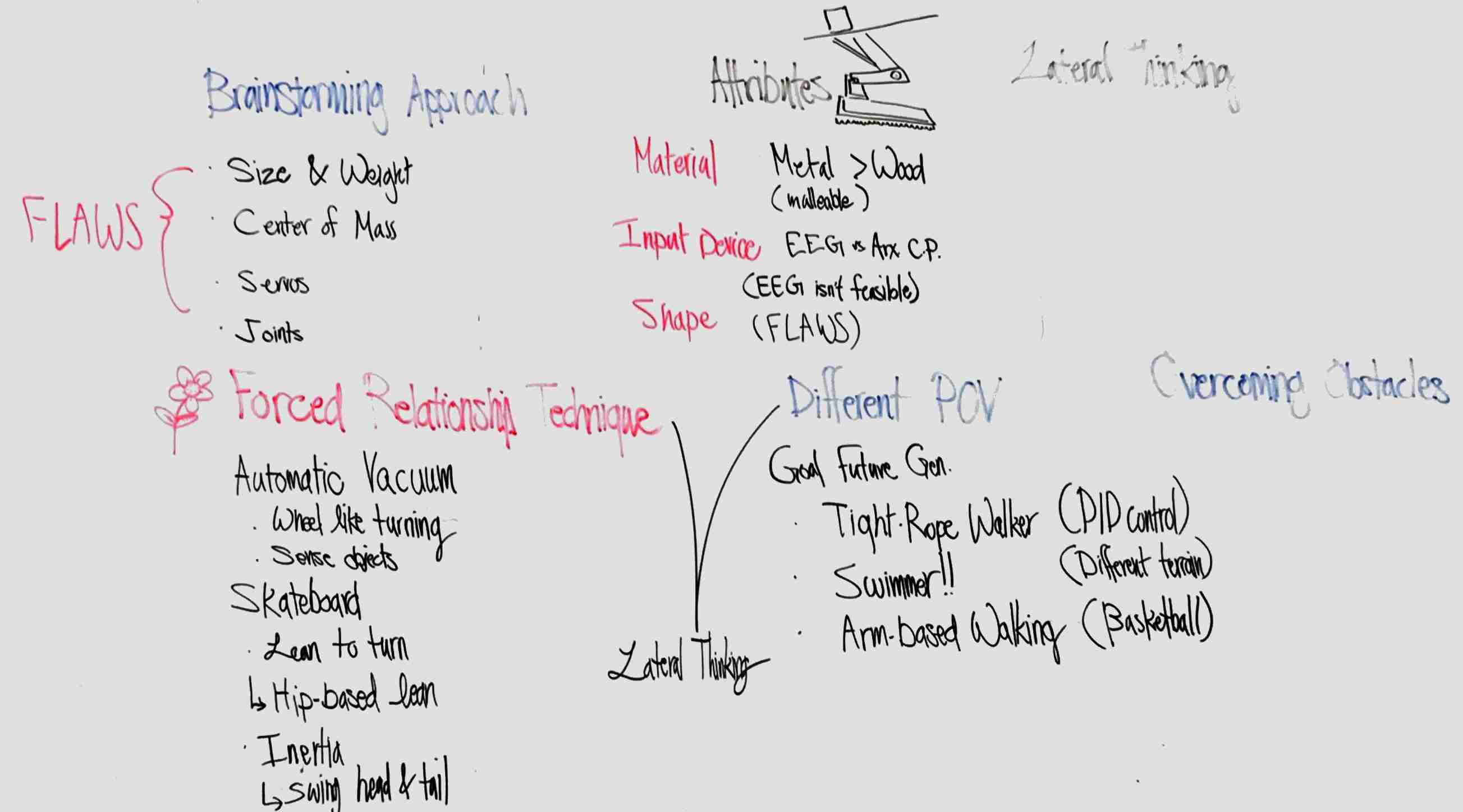
The design of the Spring 2016 Velociraptor focuses on solving flaws that may have caused previous generation Velociraptor to failed. These problems were discovered in a creativity activity using a variety of methods. Some of these methods include brainstorming approach by having the engineers listing out possible reasons that may have caused the last generation to failed, attributes listing of the robot, and Lateral Thinking using a different point of view and as well using the forced relationship technique. The team had narrow the problems to four flaws that could be improved and increase the chance of success for the Spring 2016 Velociraptor. The conclusion of the activity can be seen in Figure 1 below.
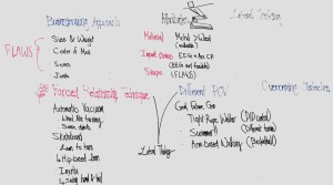
Figure 1: Creativity Activity
More information including the methods for the Design Innovation can be seen in this velociraptor blog:
Size & Weight:
One of the main problems that occurred in the Fall 2015 MicroBiped was that it was extremely heavy. This was due to the facts that everything in the previous generation was printed completely solid. The measured weight of the MicroBiped was 920 grams. With the new design of the Spring 2016 Velociraptor, the team was able to decrease the size but as well as the weight of the robot to approximately 600 grams. In Figure 2b showing the final robot’s actual weight 657 gram.
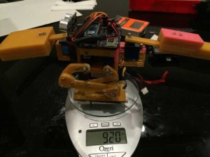
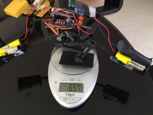
Figure 2a: Fall 2015 MicroBiped Figure 2b: Spring 2016 Velociraptor
This is a 30% reduction in weight from the previous generation. This design innovation reduces the weight of the robot, this also leads to a reduction of stress that is put on the servos. By reducing the stress on the servos we also lowered the power consumption of the robot. The engineers were able to reduce the weight by reducing the printing material needed to hold the robot together but as well as placing the servos tightly together, this method reduced the amount of material needed to be print. The team also remove the head and tail of the robot completely to reduce the weight and instead using the weight of the battery as the head and tail (Figure 2b).
Center of Mass:
In figure 2a, you can see that all the components of the robot where placed at the body, this created a problem in the center of mass. when the head and tail of the robot turn to one side it was unable to stabilize itself on one foot to change the position of the other foot. This was a critical problem because if the robot is unable to balance itself on one foot it will be unable to meet Level 1 requirement 5, which stated that the robot must be able to statically walk the course. In the new design, you can see that we have change how the robot weight is distributed. First, we remove 2 large item, the head, and the tail. By removing this part we not only significantly reduces the mass but as well as reduce the printing time for the project. Second was to instead of using 1 large battery which was placed under the body in the previous generation, we split the battery to 2 pieces and used them as the weight of head and tail to counter the weight of the body (Figure 2b).
More information can be seen on this Velociraptor blog:
Servos:
Servos are designed to provide torque not to hold weight, this was one of the flaws in the Fall 2015 MicroBiped. The weight of the head and tail of the robot were completely held by the servos. In the new design, we wanted to distribute the weight of the head and tail to the body. To accomplish this we designed a triangular shaped frame that held the head or tail. This frame in then connected to the aluminum piece of the body that held all the servos. This design put the majority of the head and tail weight to the lower aluminum body frame. However, we realize that our design still contains a flaw in which the servos still need to provide a lot of torque to lift the head and tail. Therefore, the team went back to the drawing board. To fix this problem we used the forced relationship technique, by forcing the robot to take the attribute of a garage door. The team came up with an idea of using a spring to hold the weight of the robot, this removes the stress on the servos while moving the head and tail.
More information can be seen on this velociraptor blog:
Joints:
The design of the Leg is extremely important for the stability and balance of the robot while walking. In the previous generation, there was a critical error that may have to cause the robot unable to walk. After the team carefully analyzing the Microbiped, the engineers discover that it was missing critical joints that help the robot maintain balance while walking but as well stabilizing the robot. The third joint helps the robot holds its foot parallel to the ground or the walking surface. This design can be seen in the 3D model as well as in the exploded view.
More information on Joints can be seen in this velociraptor blog:
Project Features:
3D Model:
3D model is crucial for designing our robot. Using Solidworks program to draw our model helped our team to visually see and validate the feasibility of our design. Rather than constantly 3D printing components to test for the center of mass and the mass of the legs, by simply using Solidworks mass properties utility we were able to validate and verify. By using Solidworks not only will we be able to test the feasibility of the robot but also decrease printing time and cost.
More information describing the methods of Designing and Manufacturing can be seen in this velociraptor blogs:
Sensors:
Besides the communication Bluetooth HC-06 device, the two sensors used for the velociraptor are the accelerometer and the ultrasonic rangefinder.
Accelerometer:
The choice of orientation sensor used was the ADXL335. It is an analog data type sensor capable of detecting orientation on all three axes, x, y, and z. While a gyroscope/accelerometer combination board is more accurate and inexpensive, it was unfeasible seeing the serial code in the Arduino took up over 50% of program memory, and due to time constraints, this chunk of code was unable to be edited in a short time frame. The ADXL335 accelerometer is not only simple in terms of coding, but also accurate within a couple degrees. The data obtained from the accelerometer will sense whether the velociraptor is going up an incline. Upon receiving such information, the velociraptor will initiate a different walking code moving the center of mass towards the head and allowing the velociraptor to handle walking upwards.
ADXL335 accelerometer
Range Finder:
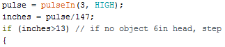
The choice of ultrasonic sensor for the velociraptor was the MaxSonar EZ3 MB1030. It is capable of detecting no less than 5 inches and up to 254 inches. There is a resolution of +1 inch due to an acoustic effect and becomes even more accurate at farther distances. It has both an analog and PWM pin for different output types, but the PWM option was chosen here for more accuracy and less noise. The velociraptor will use this sensor so that upon reaching a certain distance away from an object or wall of hindrance, the velociraptor will stop in its steps and wait for the user to choose whether to turn left or right.
MaxSonar EZ3 MB1030 ultrasonic rangefinder
More information can be seen on this velociraptor blog:
System Design:
Updated Block Diagrams:
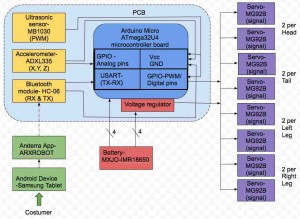
Finalized System Block Diagram
Finalized block diagrams including interface matrix and system block diagram showing interface connections and active control circuits for statically and dynamic walk showing what software blocks are being sent from Arxterra to the microcontroller.
More information can be seen on this velociraptor blog:
Microcontroller Trade-off study:
In order to determine what microcontroller that should be utilized for the brain of the Velociraptor, a trade-off study was conducted. On the basis of what pins the components that make up the build of the Velociraptor will utilize as estimated in the systems resource map as presented in the PDR and other important factors as weight, dimensions and cost the Arduino Micro Atmega32U4 microcontroller was chosen.
More information can be seen on this velociraptor blog:
Bluetooth Arxterra Communication:

Bluetooth setup
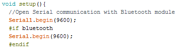
To control the Velociraptor wirelessly as stated in project level 1 and 2 requirements a Bluetooth communication between the robot and the Arxterra application on an android device needed to be established. This blog post gives an instruction on how to set up first the
Bluetooth connection; download Arxterra application, Bluetooth setup on breadboard and connection to the microcontroller, Bluetooth code in Arduino IDE and lastly configure Bluetooth on android device and Arxterra application for a successful connection. To verify the Bluetooth serial communication with Arxterra app, a setup of four LEDS on the breadboard was built to be controlled by the joystick on the app. This setup was created to show the joystick control of four different LEDS, so the future walking code could simply be implemented into the joystick code and control the Velociraptor to walk forward and turn etc.
More information can be seen on this velociraptor blog:
Experimental Results:
Power:
The power test was conducted to determine the current draw of the robot, the experiment was done using a single servo with a different mass attached to the servo lever arm. We also completed the actual power consumption of the robot after it was assembled. The total power draw of the robot was no more than 2000mA, this allows us to estimated that with 6000 mAh battery, the robot can be used for about 3 hours.
For more information about the power, the test can be seen on the Velociraptor Blog post.
Incline:
The purpose of the incline test is to determine the maximum angle the robot will be able to stand or walk on an incline. In the test, a variety of angle used to determine at which angle the robot failed to stabilize itself on the incline. Furthermore, the robot also stood in the different position on the incline to determine where the center of mass will fail to land on the robot’s foot.
For more information about the Incline, the test can be seen on the Velociraptor Blog post.
Material Strength:
Material trade-off studies have been done in order to find the suitable material to hold the weight of the head and tail. Our original design to incorporate the PCB and all sensors underneath the robot required us to have a hollow bottom piece. We needed to maximize the space which required thinner chassis for the bottom piece. After doing a quick material trade-off study as well as a material experiment we’ve decided to incorporate aluminum to certain components of our robot to reduce the weight of the robot but as well as maximize the strength of the robot.
For more information about the material trade-off studies can be seen on the Velociraptor Blog post.
Springs:
After assembling the prototype, we’ve realized the weight of the head and tail were giving too much stress toward the servos. We decided to incorporate a new design on the robot, by adding a spring to lessen stress on the servos holding up the head and tail. By adding the spring, not only did it reduce the weight on the servos to hold up, we’ve observed it also reduced the power intake by the servos.
For more information aboutSpring Experiment can be viewed on the Velociraptor blog post.
Acetone Bath:
After finalizing our prototype, in order to unify the surface texture of 3D PLA filament and Aluminum we’ve decided to use Acetone Bath to smooth out the uneven surfaces created due to 3D printing. After few trials to maximize smoothing texture, sanding the 3D materials before acetone bath gave the best results.
For more information about Acetone Bath can be viewed on the Velociraptor Blog post.
Subsystem Design:
Interface Definition:
The interface definition shows the pins that are on the Arduino Micro, the table below show how the Spring 2016 Velociraptor is connected to the Arduino Micro.
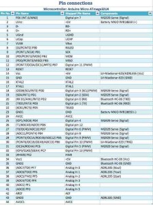 Interface Definition
More information can be seen on this velociraptor blog:
PCB Design:
This section will showcase the process of creating and testing the PCB, from the fritzing diagram, to breadboard testing, to Eagle schematic, and finally to the PCB layout.
Fritzing Diagram:
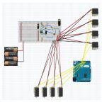
The first step towards the fabrication of the PCB is making a Fritzing diagram. Here, the microcontroller, sensors, actuators, power source, and voltage regulator are laid out. A fritzing diagram is particularly important in pin mapping on the Arduino micro. There is a communication device, a digital ultrasonic sensor, an analog accelerometer, and digitally controlled servos. The Arduino has a limited amount of digital, analog, serial, I/O, etc. pins. Upon completion of the Fritzing diagram, it is noted that there are sufficient pins on the micro to suit the velociraptor needs. Last semester for the MicroBiped, a PWM servo driver was implemented, however unnecessary.
Note the Fritzing diagram does not include resistors, capacitors, and other small elements to be implemented on the PCB in the future. Below includes:
- (4) 18650 MXJO 3.7V 3000mAh
rechargeable batteries
- MIC29510 5A adjustable voltage regulator
- (8) MG92B 3.5kg*cm @ 6.0V servos
- MaxSonar EZ3 MB1030 ultrasonic sensor
- HC-06 Bluetooth module
- ADXL335 accelerometer

Fritzing diagram
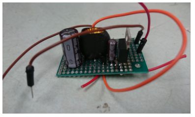
Breadboard:
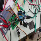
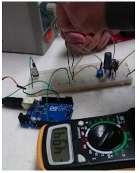
Next, the Fritzing diagram was used as a map to build the circuit on a breadboard. Because the voltage regulator had not shipped in at this point, the servos were powered separately by four AA batteries in series to achieve the optimal 6V. All components ran smoothly, which justifies the Fritzing diagram. As observed, due to the numerous connections needed for the velociraptor, the wiring could get quite messy. Thus, it is important to mount the Arduino micro directly onto the PCB to omit as many wires as possible and thus result in a cleaner project.

Breadboard testing
PCB Schematic:
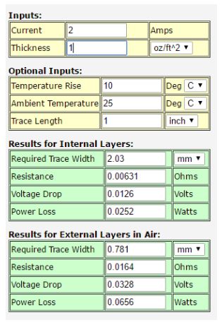
Next, the PCB schematic was created on Eagle. Starting on the bottom left are the inputs for the two sets of 18650 batteries (connected in series to a battery compartment on the head and tail). A large bypass capacitor is implemented near the batteries to reduce current transients required by the device. Small resistors were also connected in between the two batteries to help with a possible voltage offset between the two pairs. The two batteries in series provide 7.4V and these two sets in parallel double the longevity during use. One battery is 3000 mAh, so the series connection increases this to 6000 mAh. It is calculated that the project most likely draws approximately 3A, meaning the velociraptor should ideally operate for 2 hours, a perfect time span for a child to be playing with a toy.
Moving on to the right, the TO-220 package was created and laid out for the voltage regulator. The resistor values were chosen to bias the LDO regulator to output a voltage of 6V, and the recommended layout was implemented as stated in the datasheet. An enable logic conversion was mainly implemented to meet the two PCB IC requirement, but can be utilized in the future. Using two transistors and appropriate resistors, this connection is connected to a digital pin on the Arduino and allows the user to code to enable the use of the voltage regulator. For instance, if the servos are currently not in use, the voltage regulator can be shut off upon request.
On the top left are the servo connectors. There are a lot of wires due to the number of servos, thus, most of the wires were implemented on the PCB. The servos are powered directly from the LDO regulator to optimize the torque rating for the servos.
To the right is the Arduino micro, where the connections to the MCU can be seen.
Lastly to the right are the Bluetooth, ultrasonic sensor, and accelerometer pin connections. None of these will be mounted directly onto the PCB, thus using appropriate phoenix 256 connectors or pin headers will be used to allow communication between the Arduino and these devices.
More information can be seen on this velociraptor blog:

Eagle schematic
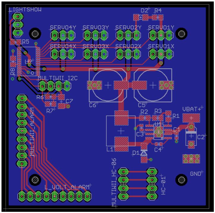
PCB Layout:
PCB layout was done using EagleCad. The dimension of our body was L: 5.60 cm, W: 4.60 cm. We have decided to mount on all the sensors and the Arduino micro on to the board itself by using female connectors. The first priority was to fit all the thru-hole components onto this size of the board while keeping all the sensors as far away as possible from the power supply due to noise. The power supply traces must be short and wide to prevent oscillation or excessive heating and make sure none of the thru-hole components must be under the mounting components to prevent it from heating. The picture below shows the final layout of the PCB.

PCB Layout
More information describing the PCB layout can be seen in this velociraptor blog:
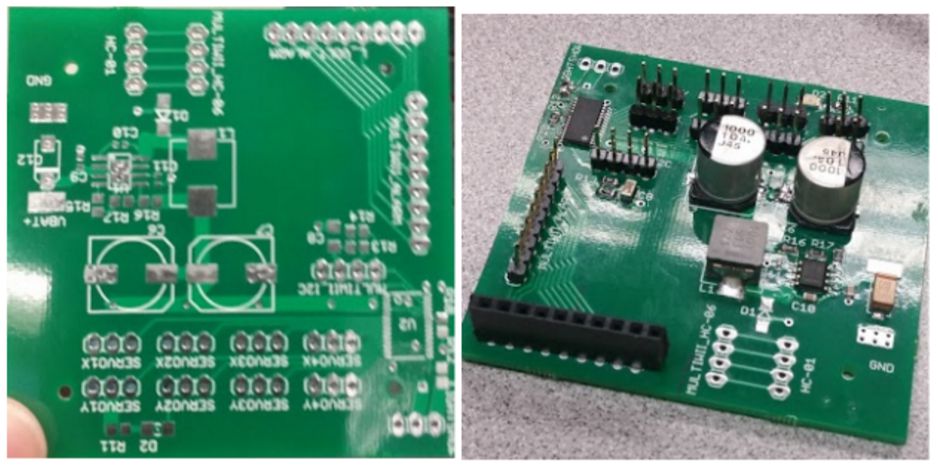
PCB Components:
The complete list of PC components is listed in the figure below. The total cost for all capacitors, resistors, NPN amplifiers, LDO regulator, heat sink, and Arduino Micro was $41.24. It is important to not only choose the appropriate packages on Eagle but also purchasing the components accordingly to these packages. There is a total of seven surface mounted parts, and the remaining is through-holes.
PCB component shopping list
Hardware Design:
Hardware design incorporates the designs we’ve made on Solidworks. When we started building a fast prototype, we’ve realized certain design features such as thickness, length or hole sizes not feasible for our overall design. When we’ve started building our prototype, we’ve observed 2 different possible errors, random & systematic errors. Random Errors are caused by unknown and unpredictable changes because 3D printing is done by building the object layer by layer using heat to melt the polylactic acid (PLA) filament, Although our 3D model part may have a thickness of 0.5 cm, when it print the thickness varies around 10%. Systematic Error usually comes from the use of the machine. There are various settings for the 3D printer which could cause the printing to be more accurate or decrease/increase printing time. By decreasing the print speed or having finer layer height may increase the accuracy of the prints but will increase the printing time.
The previous generation microbiped used 1 servo to hold and control the movements of head and tail to perform static walking. A new feature we’ve added to the Velociraptor was not only using 2 servos to control the head and tail but also attaching a spring to prevent the servos from holding up all the weight of the head and tail. Figure 1. below shows how we’ve attached the spring to the robot.
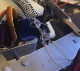
Figure 1. Servo attaching to the head on the final prototype
For more information about hardware design and the new feature can be seen on the velociraptor blog posts:
Software Design:
Before tying together all the different codes, all of the software files were initially created and tested separately. Integration of the final code includes (and were created in the following order):
- Static walking
- Stopping upon object detection
- Turning
- Bluetooth
- Walking up an incline
- Dynamic walking
One of the most important techniques in the success of static walking is the fact that even though the non-stepping foot is stationary and in place, the servos still move. This not only prevents the velociraptor from dragging this stand-still foot but also propels the body forward. Virtually, all leg servos are always moving.
Due to the SRAM memory limitations, it’s important to store all velociraptor servo angles in flash memory using LUTs. There is about 10x more program memory space versus SRAM. These servo angles were planned and stored in excel and saved as a CSV file. This organizes the data and allows these arrays to be opened up in notepad for easy transfer to the .h files utilized by the Arduino. PROGMEM was the command responsible for the main code reading from these flash .h files.
Some considerations had to be made in designing these servo angles. There have to be small incremental changes in angles to prevent any quick motions that would cause the velociraptor to become imbalanced. The steps must be designed to be reasonably lengthed for the velociraptor to make any progress in moving. The stepping leg must be able to lift high enough because there is a 0.5cm rubber divider in between the linoleum and carpet of the velociraptor’s mission objective. The angels for a set of legs must be designed so that while re-initializing on the floor, the foot keeps parallel on the floor, and these feet must be move at the same distance per time so that when both feet are on the floor and re-initializing, one isn’t moving faster than the other and causing the velociraptor to make unwanted dragging turns. Lastly, manufacturing engineer Mingyu designed the head and tail max swing so that the center of mass would be centered on top of each respective foot at the maximum capable servo angles allowing for the head and tail to move completely to the left or right.
Static Walking
The static walking was designed so that at any point in time, the velociraptor will be able to balance in place. This is very dependent on where the center of mass is. While both feet are on the floor, the velociraptor will maintain balance whether or not the head and tail are on one side or the other. When the velociraptor is taking a step, the center of mass will be centered above the foot on the floor.
Stopping Upon Object Detection
If the user no longer has a hold on the static forward walking button, the velociraptor will stop. Also, when there is an object detected within the vicinity, the static walking code will terminate and the velociraptor will come to a stop. At this point, the velociraptor will wait until the user enters turning left or right. As long as there is an object in front of the velociraptor, it will no longer pursue static walking.
Turning
There were a couple of brainstormed ideas on how to go about turning for the velociraptor. These ideas included (in order): swinging the head and tail like a baton and using that momentum to turn, one foot taking a step larger than the other, and keeping one-foot stationary as the other one takes a step and re-initializes. The last option was discovered accidentally with the preliminary static walking code and seemed to be the most viable option. Because each leg only has two servos, the ways to implement turning are limited. The cons here for turning is that the foot that is staying still will be dragged, of course. It is important that the floor and the foot have a reasonably low friction coefficient. For instance, this code would not work if both the floor and feet were made of rubber.
Bluetooth
The foundation Bluetooth code was obtained from S&T division manager Alia in a folder named arxrobot_firmware containing many Arduino files. Four buttons will be used on the Arxterra android app: forward (static walking upon pressing down, standing still while not being pressed), left and right (turning), and back (dynamic walking). Four while loops will be implemented to test these button conditions, and the respective codes will be run.
Walking Up An Incline
Upon testing the regular static walking code on the incline, the velociraptor failed and was unable to handle the 6.5* incline on the ramp. Naturally, the velociraptor “became” tail heavy and fell backward. Thus, for the incline code, the velociraptor must move its center of mass towards the front of the body to fight against the gravitational pull backward. New leg servo angles were designed in order to successfully allow the velociraptor to walk up an incline upon accelerometer information.
Dynamic Walking
Instead of using the center of mass to keep the balance at any moment of time for static walking, dynamic walking uses inertia to keep balanced while “running.” Here, the head and tail do not make full rotations left and right, the steps are smaller, and the feet are not lifted as much on the floor. Upon “startup” and “ending,” the velociraptor has to gain momentum by wiggling slowly to its complete dynamic walking loop. Using this momentum, the velociraptor is able to keep balance.
More information can be seen in these velociraptor blogs:
Verification/Validation:
Multiple tests were done to make sure that the Spring 2016 Velociraptor meet all the requirements that were set by the customer. Most of the requirements were completed. However, there were some incomplete requirements. For detail of the test plan click on the link below
Project Update:
Resource Report:
Power Report:
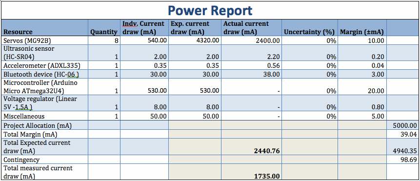
For the final updated power report, the project allocation was changed after the PDR equally to the mass report and a new project allocation of 5000mA was set. The actual current draw of the Arduino microcontroller and the voltage regulator was not possible to measure after mounted on the PCB and instead the total current draw of the final build of the Velociraptor was measured as to 1735 mA this is what the batteries need to provide power for. The MXJO IMR18650 3000mAh -3.7V- 35A batteries chosen for power supply does, therefore, prove to be sufficient to power the Velociraptor.

Power Report
Mass Report:
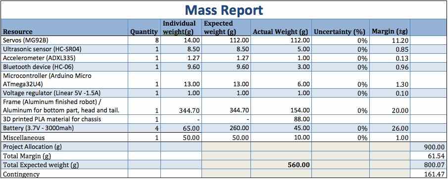
For the final updated mass report in figure 2, the project allocation has been changed since the PDR. In order to set a more realistic allocation, the resources/parts masses was added up and a contingency of 100g was set. Likewise, for the mass report as for the cost report, the original idea of the final frame cut in all aluminum acted as the heaviest post on the budget and therefore the group decided to change that to a hybrid chassis to minimize the total weight of the Velociraptor. Cutting only the bottom part holding the servos, the head and tail in aluminum reduced the weight of this post from 344.70g to 154.00 g. By printing the legs in 3D PLA filament only added another 88g to the weight of the chassis adding up to a total weight of the chassis at 242g rather than the 344.70g. The actual weight measured of the batteries turned out to be much less than the expected weight and therefore added to minimize the total weight of the Velociraptor to 560 g and thus successfully stay within project allocation.
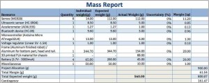
Mass Report
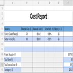
Cost Report:
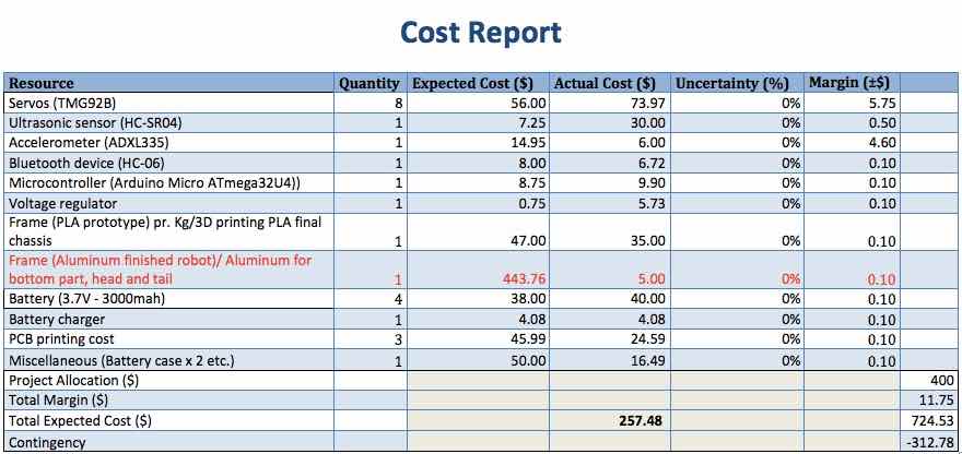
Due to the cost heavy aluminum frame post on the cost budget presented at the PDR, the total expected cost exceeded the project allocation of $400 and thus the change of parts was necessary in order to reduce the budget and stay within the limit. The final budget for the Velociraptor Spring 2016 shown in figure 2 has been reduced by changing the material used for the chassis of the robot. Instead of utilizing all aluminum for the final frame, the group decided to make a hybrid chassis made of aluminum for the bottom part holding the servos, the head and tail and print legs and feet in 3D filament Polylactic Acid (PLA). The change of parts successfully reduced the final cost of the project to a total of $257.48 and thus the final costs stays within project allocation.
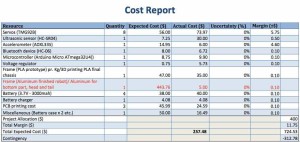
Cost Report
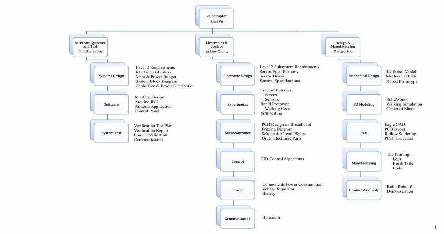
Work Breakdown Structure:
The work breakdown structure (WBS) is critical to any project as it defines the roles and responsibilities of each engineer within the project. Creating a clear WBS can help a team move forward quickly because each engineer will know their purpose for the position and this will make management much easier.
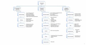
Work Breakdown Structure
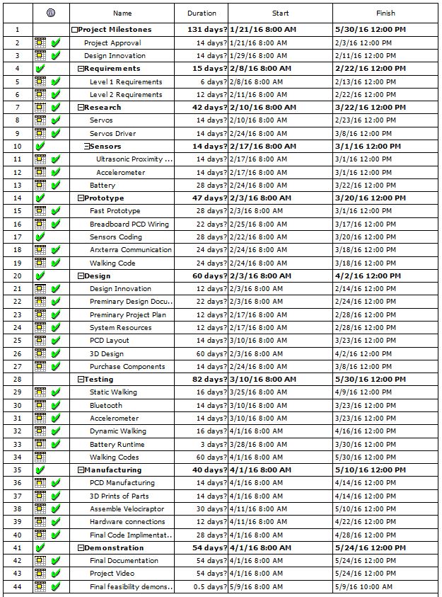
Project Schedule & Progress:
The chart below present the task that has been completed by the Velociraptor team, overall the team was able to complete about 98% of all the tasks assigned. However, we were not able to finish the final walking code giving the robot the ability to walk up an incline. Therefore, leaving us at only 85% completed on the walking code task in the testing category.
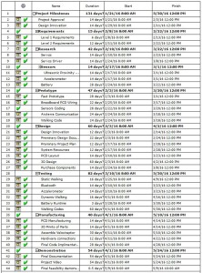 Spring 2016 Velociraptor Completed Schedule
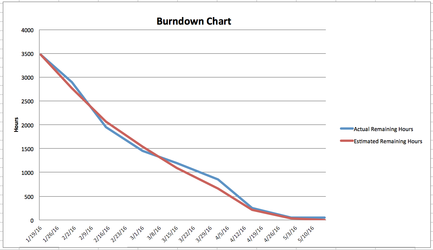
Project Burn-down:
During the critical design review (CDR) our team was extremely behind due to a delay in creating the schematic and laying out the final PCB design. This is seen below where the blue line separates from the red line during the first week of April. However, a week after CDR the team was able to fix all the problem as well as assembling the final product. When all the problem were fixed, we also finish assembling the robot. This allowed us to get back on schedule which is shown in the Final Burn-down chart below.
 Final Burn-down Chart
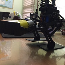
Project Video:
The final video presents the engineering methods and the process of creating the Spring 2016 Velociraptor biped. To see the process using the engineering methods click on the image Spring 2016 Velociraptor or the link below.

Spring 2016 Velociraptor
Velociraptor Walking the figure 8
Final Video: Spring 2016 Velociraptor Final Video
Concluding Thoughts:
- Before starting a project, the team should find all the problems and find ways to improve the project.
- The key to of having a successful project is to make sure you are always ahead of the planned schedule. There will always be obstacles that will slow your project down. If you are ahead, these obstacles will not affect your deadline significantly.
- Have your first prototype within the first month of class. This will help you find the problems in the early designs and fix it before any decision are made with a faulty designs.
- Teamwork is critical, the project cannot be completed by an individual with the given time. Make sure that everyone are following due dates.
- In the case when the project falls behind, request help immediately.
Project Resources:
Kevin Lundberg – 3D Printing & PCB parts
Mingyu Seo – 3D Printing
Khoi Vu – Wood Workshop
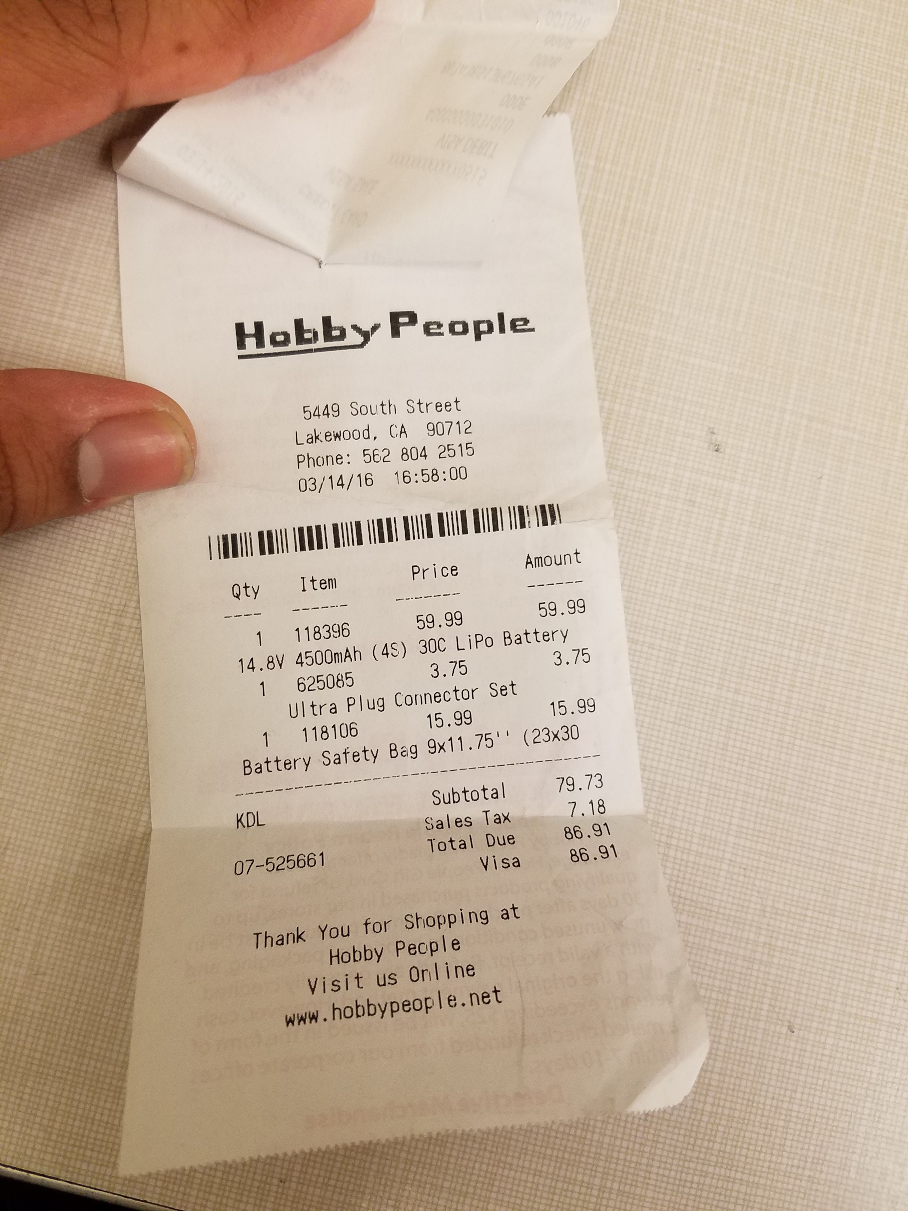
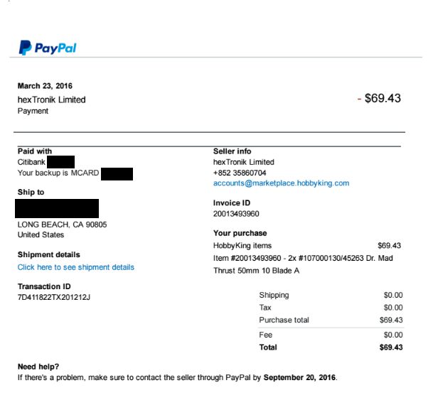
Banggood – Robot’s Parts
Parallax – PCB Parts
Mouser – PCB Parts
Osh Park – PCB Fabrication