Spring 2016 Velociraptor: 3D Smoothing

By: Mingyu Seo (Manufacturing & Design)

Introduction:

In order to accommodate mass budget of the robot, our team has decided to create the legs and the top using 3D filament polylactic acid (PLA). One of the drawbacks of using 3D printing method is the result of the prints having ridged surface texture created by the layer by layer printing. There are multiple solutions for smoothing surface of PLA 3D prints to make the final product better. We will be looking at 2 methods that are safe and simple to apply.

3D printer setting:

Layer height (mm): 0.25

Shell thickness (mm): 1.2

Bottom/Top thickness (mm): 1.0

Fill Density (%): 25
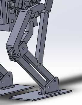
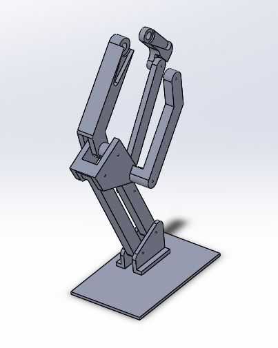
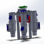
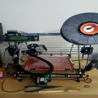
(Leg Picture here)

The picture shows the one of the finished print for the right leg, which we could clearly see the ridged surface texture.

Smoothing Methods:

  1. Acetone Bath
  • Acetone bath is one of the most commonly used method to smooth out PLA and ABS materials. It melts the outer plastic and creates a smoother and glossy looking surface. Acetone bath is the simplest and fastest method to smoothing 3D materials.

Procedure:

  • (Optional) Sand the 3D material using sandpaper (P320 most optimal) to smooth out the ridged surface.
  • Pour enough acetone in a container (Just enough to fully submerge the part)
  • Keep the part submerged for 40 ~ 60 seconds
  • Take it out and dry.

(*CAUTION: make sure to use gloves when handling PLA due to melted plastic)

2.  XTC-3D epoxy

  • XTC-3D epoxy has lately been getting attention in 3D community which uses 2 liquids that are mixed together and then brushed onto 3D prints. Due to XTC-3D is a protective coating that does not melt plastic, so sanding all parts before applying is highly recommended.

Procedure:

  • sand all surfaces of the 3D parts using P320 or P600 sandpaper.
    • starting off with P600 may be a safer option,
  • Apply coating on to 3D parts using a brush.
  • Dry for minimum 4 hours.

XTC-3D coating works with all 3D materials as well as wood, plaster, fabric, cardboard, and paper. It’s easy to apply but takes a long time to dry. It takes minimum 4 hours and may need to be applied several times to have a unified smooth surface.


Conclusion:

To decrease production time, our team has decided to incorporate acetone bath to our final product. Program Level 1 Requirement 1 states the Velociraptor biped robot shall demonstrate its feasibility as a toy. To fulfill this requirement, acetone bath will not only help to smooth out the rigged surface but also improve the look of the final product.

Spring 2016 Velociraptor: Hardware &Simulation

By: Mingyu Seo (Manufacturing &Design)

Introduction:

The purpose of this blog is to show the feasibility of the design we’re going to incorporate in to our robot. Using Solidworks, we’ll be able to validate center of mass of the robot when we’re performing static walking. Also by using the simulation on Solidworks, it’ll show the basic motion of the robot walking. Following hardware design will explain the problems and solutions we’ve made to find the most suitable design of Velociraptor.

Requirements:

Project Level 1:

  1. Requirement 1 states the Velociraptor shall resemble a Tyrannosaurus class of dinosaurs as given in the objective.
  2. Requirement 2 states the word “biped” is defined as having two feet; therefore, the Velociraptor shall use two legs to move.
  3. Requirement 4 states the Velociraptor shall be able to statically walk on all surfaces of the course
  4. Requirement 5 states the Velociraptor shall be able to dynamically walk on flat surfaces of the course.

Project Level 2:

  1. Requirement 4 states to resemble a Tyrannosaurus class of dinosaurs, the chassis of the Velociraptor shall be cut out in hollow body parts to assemble a frame-like body structure in a material that is cost effective
  2. Requirement 6 states to maintain balance while performing static walking, a head and tail shall be implemented to the chassis of the Velociraptor

Overall, the design of the robot must resemble a Tyrannosaurus class dinosaur, that walks on two legs, and by incorporating the head and tail will help keeping the robot balanced when it’s performing static & dynamic walk by shifting the center of mass using the weight of the head and tail. New designs were incorporated in to our new design to accommodate mass, price, and power budget.

Hardware Design:

1.1

Figure 1. Final Design of Velociraptor (excluding sensors)


2 (2)

Figure 2. Exploited View of Velociraptor

First Design:

right leg

Figure 3. First design of the joint

Figure 3. shows the first design of the joint which incorporates the 3rd joint that was missing from the previous generation. The new design also incorporates a new design of the ankle where it’s connected with 2 parts rather than 1 that holds the leg and the foot, which helps the foot to stay parallel to the surface at all times.

Problem: when assembling the first design, we had few design problems

  1. The 3D printed parts were not sturdy
    1. Not strong enough to hold up the weight of the body
    2. putting too much pressure on the base of the foot started bending parts.

Second Design:

kinda new right leg

Figure 4. 2nd Design of the joint

Figure 4. incorporates the fixed design of our first design. We made all our parts minimum 0.3 cm thickness to prevent our parts from bending. The front joint that connects from front servo to the knee has thickness of 1.2 cm to have a more stable stance, and make sure it’s sturdy enough to hold the weight of the robot.

Problem:

  1. By increasing the thickness of the joints also increased the angle the head and tail must turn in order to shift the center of mass when performing static walk.
  2. When designing the 3D model, the design did not compensate the extra length added due to servo caps.
  3. The thickness of the foot was still too thin.

Final Design:

New right leg

Figure 5. Final Design of the joint

Figure 5. shows the finalized design of the leg of Velociraptor.

Final Features:

  1. Shifted the front top joint (connecting from front servo to the knee) to the out in order help the robot to find center of mass by moving the head and tail less.
  2. Also have incorporated the placement for the servo caps to bring it closer to the center.
  3. All parts have minimum 0.3 cm to have a stable stance when it’s performing static walking.
  4. Extra length toward the back and outer side of the foot to have a more stable and balanced walking.

PCB placement:

First when we were designing the robot, we have decided to place all the sensors and the pcb underneath the servos. After finishing our PCB layout, we have found the size of the board too big to be placed under and due to the size of the voltage regulator it was not applicable to fit all the components under the robot. In order to solve this problem, we have decided to create a clear casing on top of the robot and place all our components in.

Design Features:

  1. Bottom of the case have been cut out in order to bring the wires underneath and hide it.
  2. hole has been placed on the front side of the casing to place the ultrasonic sensor.
  3. casing will be made with a clear PLA filament to show the components inside.
pcb placement

pcb placement2 Figure 1. Design of the casing to hold up the PCB and also the top view of the casing


Simulation:

The simulation below shows the motion of the Velociraptor when it’s performing static walking.

In order to balance on one foot, we need  to move the center of mass above the supporting leg by moving the head and tail toward the supporting leg for counter weight.

ezgif.com-video-to-gif

Conclusion:

This simulation shows the given dimension of the 3D model shows the feasibility of the design of the Velociraptor, and confirms the level 1 requirement 4, which states the Velociraptor being able to statically walk across the full course. The design that we have incorporated have been tested and resulted as successful when we’ve performed static walking. Biggest issue was trying to keep all wires and components hidden but due to the size of the PCB and the size of the voltage regulator heatsink we have decided to mount it on the top of the robot. The Head, Tail, and bottom plate for the robot was made with Aluminum, but the legs, top plate, and the PCB casing will be printed using PLA filament.

Current Draw spring 2016

Posted by: Luis Valdivia(Project Manager)
Written by: Kevin Nguyen(Electronics and Controls)


Table of Contents:
– Introduction
– Shunt Resistor
– Results

Introduction:
We encountered a problem while measuring the current draw of the motors; the motors were drawing too much current for the multimeter to read. To solve this, we used a shunt resistor setup to measure the voltage across the resistor and calculate our current draw. Using this method, we can avoid directly measuring the high current which could damage our multimeter.

shunt resistor123

Fig 1.1 Shunt Resistor Setup

This setup is used to measure the current draw of high powered devices. Our load would be the motors and the supply is a 14V source.


Shunt Resistor:
The specs of the shunt resistor is 300A, 50mV. That means that the resistor would have a 50mV voltage drop at the maximum current of 300A. Since Ohm’s Law says that the voltage is proportional to the current across a resistor, we can simplify that to 6A per mV. Knowing this, we can calculate the current draw by multiplying the measured voltage by 6A/mV.

Another alternative to calculating the current draw would be to calculate the resistance of the shunt and divide that by the measured current draw. Using Ohm’s Law we can calculate the resistance of the shunt to be:

50mV = 300A*R

R = 50mA/300V =  0.1666mOhms

Shunt Resistors typically have very small values so that it doesn’t affect the circuit. The tolerance is very small, 0.1%, for accurate measurements. To measure the current draw using this method, we divide the measured voltage by 0.16666mOhms.


Those two methods described above are 2 ways of realizing an identical solution. Multiplying by 6 is the same as dividing by 0.16666.

shuntcomponent123

Fig 1.2 Shunt Resistor

Low Resistance, Low Tolerance resistor that serves many applications. One of its purposes could be used for measuring high current.


Results:
Using this method we were able to accurately measure the current draw of our high powered motors. The results we got was that each motor drew approximately 11.85A at full throttle with our setup. 4 Motors would draw a total of 47.4A. Using this data, we determined that our battery was safe to use with these motors. The battery we have is capable of safely supplying 135A continuous load current which is far above what we require.

Spring 2016 Velociraptor: Critical Design Review Debrief

By: Khoi Vu (Project Manager)


The Critical Design Review (CDR) purpose is to present data and progress of the project to the President and the Customers. The CDR presents the executive summary, system and software design, experimental results, interface definition, and the custom PCB design that will be used on the final product.


For full PPT of CDR click on the link below:

https://www.dropbox.com/s/c61ju4onj17a5zi/CDR.pdf?dl=0


Debrief:

  1. In the executive summary, there should be an exploded view of the 3D model of the product that contains the name of the person responsible for each slide.
  2. Executive summary should always be short, summarizing the project design and design features.
  3. System design should not show the PCB.
  4. Servos tests in the experimental result were done incorrectly; a stick lever arm was used as lever length changes during rotation. A circular lever arm will give a more accurate result because it will have a consistent radius.
  5. Incline testings did not show how the robot will respond to the incline when it is walking sideways on the incline instead of walking up the incline.
  6. Power test did not give a accurate result of power consumption by the servos, a ammeter should be used to connect in series to find the actual power consumed by the robot since the robot has been completely assembled.
  7. PCB schematic was not presented clearly; a white background with black lines would be much easier to see.
  8. Since the robot is taking in a lot of Current (5 Amp), a fuse is recommended to protect the components of the robot.
  9. Active Control Circuit is missing for the dynamic walking requirement. The team should still acknowledge all requirements that have been listed.
  10. The team should consider how the robot’s foot should always be parallel to the ground and not always the x-axis. This may cause failure when walking over obstacles and inclines.
  11. Verification and Validation tests needs to show more results.
  12. Resource report values that were measured should not contain any uncertainty since the values were measured and not estimated.
  13. Cost Budget should also contain the cost of parts that were donated to show a more accurate cost of the whole project.
  14. Final printing should not start when PCB size is not known yet.

Note:

Number 5 was tested and the results were shown in CDR PPT,  however, the team may have not discussed the results in depth.

Number 14 printing only consist of parts such as the legs that have been enclosure, the team have not finalize the design for the PCB container, therefore, we have not printed the PCB case.


UFO Spring 2016 – EDF Area Coverage With Flap Length Calculations

Written and posted by: Luis Valdivia (Project Manager)

Table of contents:
Introduction
Approach
Formulas
Conclusion
Possible Solution


Introduction:
When attempting to angle the thrust coming from the Electric Ducted Fan (EDF), there is a risk of covering the ducted fan area to prevent vertical flight. This post will explain our research done to determine the maximum area allowed to control the aircraft without losing vertical thrust.


Approach:
Using middle school math, we can figure out the area of the flap size and the area of the duct.

Figure 1.1 demonstrates the area of the duct being covered by the flap, along with formulas for area. 

areamiddleschoolmath123

Because of the size of the EDFs, we will assume the length of the flap is fixed at 55mm. The Width of the flap will depend on the area of the opened duct, aka the area of the circle. For a fully opened duct (meaning no coverage of the circle) we can produce a maximum thrust of 650g with a flap of length 0mm. With a partially opened duct (meaning half of the circle is covered) we can produce half the thrust of 324.99g with a flap length of 27.5mm. Finally, for a fully closed fan duct we will produce 0g of thrust with a flap of length 55mm.
Inputting our 3 sets of values into excel, we can fit a linear line into our data plot to obtain the equation of our line. This equation will help us calculate more values to get a better understanding of the range between flap length and available output thrust.

Figure 1.2 Linear fit plot of Duct Area vs. Thrust (with equation of line)

AreavThrust123

Figure 1.3 Linear fit plot of Duct Area vs. Flap Length (with equation of line)

ductvflaplength123


Formulas

Area of duct = 2*π*(radius*percentage of opened duct)

Length of flap = 55mm(100 – percentage of opened duct)

Area of flap = length of flap * 55mm

Thrust (g) Area of duct Length (mm) area of flap (mm^2) % of open fan
650 345.4 0 0 100.00%
643.48137 341.946 0.55 30.25 99.00%
636.9815581 338.492 1.1 60.5 98.00%
630.4817463 335.038 1.65 90.75 97.00%
623.9819345 331.584 2.2 121 96.00%
617.4821227 328.13 2.75 151.25 95.00%
610.9823109 324.676 3.3 181.5 94.00%
604.4824991 321.222 3.85 211.75 93.00%
597.9826872 317.768 4.4 242 92.00%
591.4828754 314.314 4.95 272.25 91.00%
584.9830636 310.86 5.5 302.5 90.00%


Conclusion:

As you can see, the thrust output from the EDFs will beginning to decrease if we cover the duct. Although, from a previous blog post we mentioned the necessary thrust to lift the weight of the aircraft. The necessary thrust to lift a quadcopter weighing in at 1291g is 645.5g thrust for each EDF. From our table above, it seems like covering the duct at anything greater than 0.55mm will prevent our UFO from lifting off the ground.


Possible solution:

In order to continue the project with thrust vectoring, the EDFs will have to be swapped with fans of thrust greater than 650g. Another solution is to reduce as much weight as possible to lift the UFO and vector the thrust we a reasonably sized flap.  

Bluetooth Module Update Spring 2016

Written by: Anthony Becerril (Mission, Systems, and Test Engineer)

Posted by: Luis Valdivia (Project Manager)

Table of contents:

  • Introduction
  • Previous work
  • Current Progress
  • Additional Resources


Introduction:

The current UFO Quadcopter is being modified to communicate via bluetooth in addition to the already existing RC communication. The following will discuss previous work and current progress on bluetooth communication implemented with the quadcopter.


Previous Work:

Previously the bluetooth module HC-06 was used in combination with the HK MultiWiii flight controller to monitor and control the quadcopter. A GUI is also provided alongside with the MultiWii controller and can be used to display information from the MultiWii from the following: triple axis gyro, accelerometer, barometer, magnetometer. Show below is the GUI’s display.

Figure 1.1 Multiwii Flight Telemetry GUI:

coolgui

The software can be found via the internet or the latest version found at this time can be downloaded here. Beyond that, in the past the Arxterra application has been used to sync up the phone to the desktop version of Arxterra and demonstrating the camera function. Further details on how bluetooth works can be found in the previous post on bluetooth from Fall 2015.


Current Progress:

Rather than pick up where previous work left off, discussion on whether a new approach was needed had happened. The results were using a new bluetooth module and researching for a phone application to help monitor and control the quadcopter.


The bluetooth module we decided to use what the HC-02 android compatible module. Buying it from Hobby King also provided easier to use wires to connect it with the MultiWii board. When attaching to the quadcopter this module is easier to attach due to not having to deal with pins on a breadboard like you would with other modules.

Figure 1.2 Bluetooth Module and Connector:

bluetooth

For setup, we followed the quick overview video as reference and first wire the module to the MultiWii controller. The wire connect as follows:

Figure 1.3 Wiring Diagram for Multiwii 328p:

bluetoothpinout

After setting it up, we power the MultiWii board to turn on the bluetooth module. When syncing up the module, it initially blinks due to not being paired to any device yet. When seeking to pair it is highly recommended to use an android device. When pairing look for the device, “HC-02” of the devices available. Then there is a prompt to input the pairing code which by default is 1234. This code can be changed with some research online. If pairing was successful then the bluetooth module should now be a solid light rather than be blinking. Now the module is paired and ready to be used with android applications.


This is a big step in communications due to the final goal of being able to control the quadcopter via phone application. Further research is going to be done to implement a third party application. This will then lead to being able to do the same with the Arxterra android application.


Additional Resources:

Previous Blog Post: Learning To Use a Bluetooth Module (Fall 2015)

Previous Blog Post: Bluetooth Interface to Arxterra Application (Spring 2015)

Multiwii MWC FC Bluetooth Module (HC-02)

Multiwii Software

MultiWii 328P + Bluetooth Module Quick Overview

UFO Mass-Thrust Trade Off Studies Spring 2016

Written and posted by: Luis Valdivia (Project Manager)

Table of contents:

  • Introduction
  • Formula
  • Tests
    • 1291g
    • 1391g
    • 1504g
  • Conclusion
  • References


Introduction:

This document highlights the importance of weight for the UFO abducted quadcopter. Each EDF delivers a maximum thrust of 650g. Running all 4 motors should be able to lift the quadcopter, if the aircraft is not over weight capacity.


Formula:

In a hobbyking forum, we found a formula used to determine the allowed weight for certain thrust values carried by the motors.


Thrust per edf = (Weight of aircraft * 2)/Number of fans being used

We can turn the formula around and solve for the maximum weight allowed on the UFO abducted.


Weight of aircraft = (Thrust per edf * Number of fans used)/2


In our case we will have an allowable weight of:

Weight of aircraft = (650 g* 4 EDFs)/2 =1,300g


Tests:

Our first test, we attached the 3d printed legs we intended as a replacement of the original landing legs.(also included the battery, 4 EDFs, 4 ESCs,  multiwii flight controller, wireless receiver, lipo low voltage indicator and support attachments for the frame) . The weight of the vehicle for this test was 1291g (9g below our limit).


The video can be seen here


Our second test, we attached the ducts to hold the servo motors and also included the battery, 4 EDFs, 4 ESCs, 4 pairs of 3d printed legs, a multiwii 328p flight controller, wireless receiver, lipo low voltage indicator and support attachments for the frame. The weight of the vehicle for this test was 1391g (91g above our limit).


The video can be seen here


For our third and final test, we attached the servo motors (x4) and also included the battery, 4 EDFs, 4 ESCs, 4 pairs of 3d printed legs, 4 ducts to hold the servo motors, a multiwii 328p flight controller, wireless receiver, lipo low voltage indicator and support attachments for the frame. The weight of the vehicle for this test was 1504g (204g above our limit).

The video can be seen here

Conclusion:


As a conclusion, we determined the thrust vectoring control for stability would not be possible with the current set up we have. Possible solutions: replace current set up with stronger fans, tilt current EDFs to vector thrust, and finally side fan(s) similar to a helicopter. Table 1.1 demonstrates the necessary thrust per EDF (assuming 4 EDFs are being used) to lift our vehicle. Strictly, anything above 1300g WILL NOT LIFT.


Weigt of vehicle (g) Thrust per EDF (g)
1291 645.5
1391 695.5
1504 752

Table 1.1 Above demonstrates relation between mass and required thrust, for liftoff. 

References:

  1. http://www.hobbyking.com/hobbyking/forum/forum_posts.asp?TID=38561

PCB Design: Schematic – Spring 2016

Posted by: Luis Valdivia(Project Manager)

Written by: Kevin Nguyen(Electronics and Controls)


Table of Contents:

  • Introduction
  • Full EagleCAD Schematic
  • Step-Down(Buck) Switching Regulator
  • Servo Status Indicator
  • PCA9685 Connections
  • 3-Pin Headers for Servos and Lightshow
  • Pin Headers for Low Voltage Alarm and Bluetooth


Introduction:

One of the main tasks of the Electronics and Controls Engineer is to design the circuit for the PCB. This post will explain the reasonings behind the chosen components on our PCB.

pcbschematic1.1

Fig 1.1 Full EagleCAD Schematic

This is the full schematic for UFO Quadcopter’s PCB. Further detail will be shown in the following figures.

pcbschematic1.2

Fig 1.2 Step-Down(Buck) Switching Regulator

Tasked with redesigning the PCB from last semester, I chose to replace their adjustable LDO voltage regulator with an LMR14050 buck converter. The reason for this is because LDO regulators lower voltage by burning excess power while buck converters lower voltage by storing the excess power. For the quadcopter’s circuit, a 5V output is required from a 14.8V supply. Dropping that much voltage using an LDO will waste a lot of power. Using the buck converter, the supply voltage will be able to drop down to 5V while maintaining enough current to power the PCA9685, servos, and light show. Capacitors are placed in parallel with the input and output to smooth the ripples since switching circuits may cause some fluctuation. The inductor is a storage device used for storing energy. The size of the inductor will determine the current output of the buck. The LMR14050 can output a maximum of 2A, which will be enough to power the servos and light show. The resistor network on the right side of the buck is used to adjust the voltage. The values I used will result in a regulated 5V output.

pcbschematic1.3

Fig 1.3 Servo Status Indicator

This is a simple LED status indicator. It is connected to the same node that powers the servos. If the LED is lit, the servos should be powered on. The resistor is used to lower the current to protect the LED. With a constant voltage of 5V, the higher the resistance the lower the current.

pcbschematic1.4

Fig 1.4 PCA9685 Connections

The PCA9685 is the same chip used within the Adafruit Servo Driver. Since weight is a major issue for our project, I chose to implement the servo driver in our PCB so that we won’t have to add a third board to our setup. The left side of the PCA shows the connections for power and input. The right side is the PWM outputs for controlling the servos and light show. The PCA is connected to the MultiWii through I2C. The MultiWii is the master device and the PCA is the slave device. The Serial Data and Serial Clock signals from the MultiWii will be able to control all 8 servos and light show. The A0-A5 pins are used to set the address of the PCA. Since we are only using 1 slave device, I grounded all addressing pins which would set the PCA address to 0.

pcbschematic1.5

Fig 1.5 3-Pin Headers for Servos and Lightshow

8 3-Pin Headers are included for the servos. 4 for the servos rotating in the X direction and 4 for the servos rotating in the Y direction. A 3-Pin Header is also used for the light show. Each header includes a pin for data, power, and ground. The control signal will be coming from the PCA9685. These components will be powered by the regulated 5V from the buck.

pcbschematic1.6

Fig 1.6 Pin Headers for Low Voltage Alarm and Bluetooth

To keep things nice and tidy, I made pin headers on the PCB for the voltage alarm and the bluetooth module. This will hold all the components on the board and keep things from swinging around during flight.

UFO Light show setup

Posted by: Luis Valdivia (Project manager)

By: Anthony Becerril (Mission, Systems, and Test Engineer)

Table of contents:
    Intro
    Step 1: Hardware via Circuit
    Step 2: Software via Arduino integration
    Additional Resources


Intro:

This UFO Quadcopter post is in regards to the custom light show that is created through use of a 24 LED Adafruit NeoPixel Ring and follows along previous light show posts. The following will break down the proper setup for hardware and software and additional resources available.


Step 1: Hardware via Circuit

The first step consists of setting up the appropriate circuit to properly power the ring. The following setup is emulated via breadboard although it is to be implemented onto the Printed Circuit Board (PCB) for efficiency and optimal space on the quadcopter. Protection of the ring is important for the lifetime of the LEDs. As stated by the Adafruit NeoPixel Best Practices, The following should be followed:


  • 1000 microfarads capacitor should be added in parallels to power and ground terminals
  • 300-500 ohm resistor between arduino data output to neopixel data input
  • Minimize distance between arduino and ring
  • Avoid connect ring to a live circuit. If necessary, connect ground first, then power, then data. Disconnect in reverse order.


Other practices are listed along with more details on powering, library installation, and more. The link should be thoroughly explored before moving forward. The ones listed are important for this specific setup mainly due to the high voltage battery and making sure the appropriate precautions are taken. Figure 1-1 (below) gives an overview of our circuit used.

Figure 1-1 (Fritzing diagram)

lightshow

We only used 3 terminals of the ring: one power, one ground, and one data. The power supply for the emulation is a 5 volts power supply whereas when using the PCB we will be implementing such components to step down the LiPo battery used to power the quadcopter.


Step 2: Software via Arduino Integration

After completing the hardware, software comes next through use of the Arduino IDE. Following the Arduino Library installation, the Arduino software is now able to test the ring with the “strandtest” example code to result as follows:


https://youtu.be/qTRpvA696YY


From all this, the possibilities of different lights show are many when considering the many different patterns available. Next steps are creating a code to be operational via bluetooth then having successful Arxterra application control for a custom light show settings.


Additional Resources:

Previous Blog Post: How to Light Show (Spring 2015)

Previous Blog Post: Creating Neopixel Ring Light Show (Fall 2015)

Adafruit NeoPixel Ring – 24 x 5050 RGB LED with Integrated Drivers

Adafruit NeoPixel UberGuide

Spring 2016 Velociraptor: PCB layout

By: Mingyu Seo (Manufacturing & Design)

PCB Design:

For our design, we’ve started off by planning where our PCB is going to be mounted. Rather than placing it on top or inside the body frame, we’ve come up with mounting the PCB underneath the body to cover wires connecting all the components together. So, we have decided to mount the Arduino Micro as well as the accelerometer in order to minimize the number of wires connecting to the PCB. We decided to wire the Bluetooth toward the tail and the accelerometer on top to make sure it’ll be able to detect obstacles ahead.

Problems:

  1. The voltage regulator may cause too much heat.
  2. Minimum space to place all components
  3. Sensors mounted directly to the board must either be mounted so that they hang off the edge of the PCB, or the packages must be edited to include the physical shape of the device to avoid overlap of components.

Solutions:

  1. we will be using thru-hole heatsink method rather than PCB copper heatsink. Also by placing the voltage regulator to the corner, we will be using TO-220 Heatsink. 
  2. Due to very little space provided for PCB layout, we will have to make sure to place the power supply as far away from the Bluetooth, accelerometer, and ultrasonic sensors as possible.
  3. we have a 5.12cm x 4.8 cm PCB layout, which must incorporate Arduino Micro, Accelerometer, Bluetooth, ultrasonic sensor, 8 Servos. By placing all the sensors on one side, we will be able to mount the accelerometer off the edge of the PCB, and connect Bluetooth and ultrasonic sensor with a wire.


PCB Layout:

PCB layout FINAL 2

Finalized PCB layout

PCB layout FINAL

Finalized PCB layout Wiring