Spring 2016 Velociraptor: Updated Block Diagrams

By: Camilla Nelly Jensen (Systems Engineer)

According to the Critical Design Review Debrief, the team had made some error in the CDR powerpoint. These errors have been fixed and shown below.

For the System Design, the Active Control Circuit for the software blocks of the dynamic walk was missing and thus that circuit has been updated along with the rest of the system block diagrams for the Velociraptor in this blog post. Likewise, the interface matrix has been updated in order to show leftover available pins of the microcontroller.


blog post pic

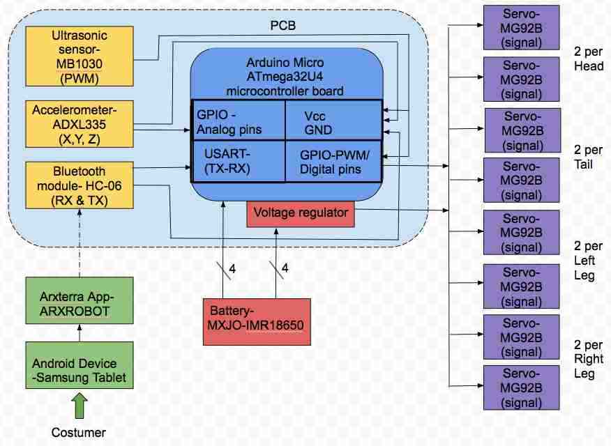
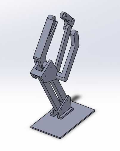
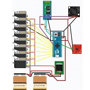
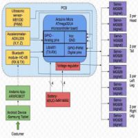
 Figure 1: Updated System Block Diagram

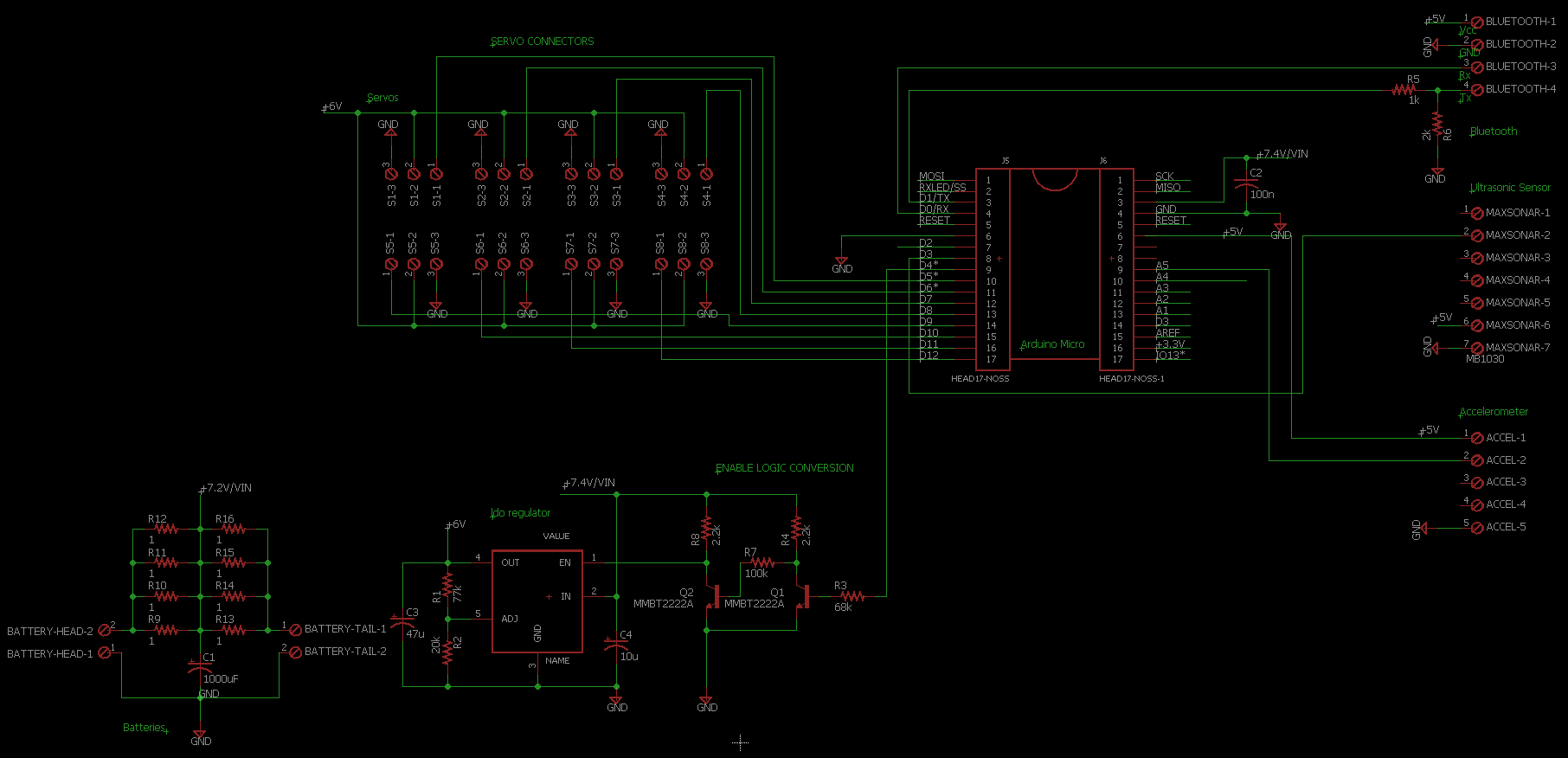
The system block diagram displayed in figure 1 shows the interface connections of the inputs (Arxterra application) and outputs (servos) of the Velociraptor. For the updated version both sensors, ultrasonic and accelerometer and Bluetooth module have been mounted on the PCB along with the microcontroller, some directly into the pins of the microcontroller in order to minimize the use of wires to establish connections. Since microcontroller requires voltage input of 7-12 V, two batteries in series (3.7V*2=7.4V) have been placed on the head to provide that. The other two batteries have similarly been placed in series on the tail but as the servos require an input voltage of 6V the batteries have been connected to a voltage regulator to downsize the 7.4 V to match the 6V for the servos. The location of the batteries has been chosen to minimize the weight on the body of the robot.


Interface matrix Final

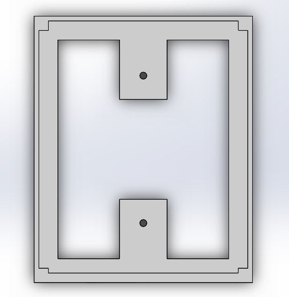
Figure 2: Interface matrix

Figure 2 shows the components of the Velociraptor’s pin connections and the leftover available pins on the Arduino Micro Atmega32U4 microcontroller board. The interface matrix hasn’t changed much from the PDR since we decided to go with the original components after testing other components. This comprises testing of the accelerometer where the first objective was to use the MPU-6050 3 Axis Gyro Accelerometer Sensor for the Velociraptor to detect an incline. But after testing the accuracy of the gyro-accelerometer is showed an error of 1-2° degrees and took up too much memory of the microcontroller and thus the group decided to go back to the original accelerometer ADXL335 that detected inclines more accurate and takes up less memory. Likewise, with an ultrasonic sensor the first intent was to utilize the HC-SR04 Ultrasonic Ranging Sensor but during tests, the sensor would loose signal and thus not valid to use for the Velociraptor to detect obstacles. Therefore, the group decided to change to the MB1030 LV-MaxSonar-EZ3 Ultrasonic Rangefinder, which operated to the accuracy listed in the datasheet and did not loose signal. The ultrasonic sensor is, therefore, the only component that has been changed for the setup and the LV-MaxSonar-EZ3 utilizes one pin less than the HC-SR04 only a TRIG pin.


Software block statical w_ legend

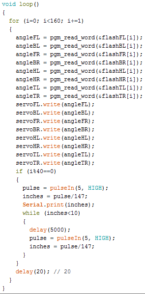
Figure 3: Active control circuit for statically walk

The software block diagram in figure 3 shows how the input command is sent via the Bluetooth module and through what pinouts to reach the Arduino firmware blocks to be decoded and handled before sent as subroutines to the output components, the servos to act the subroutines sent. The sensors, ultrasonic and accelerometer also gives inputs to the subroutines of the servos and thus if the ultrasonic sensor detects an obstacle the input routine shall block the MOVE subroutine for the servos. Likewise with the input from the accelerometer, if it detects an incline, an input routine will be sent to the servos subroutine and change the subroutine (walking code) in order to adjust to the incline.

For the Velociraptor, we are only sending commands from the Arxterra application to the servos to perform and not receiving any data from the components to the Arxterra application. The orange example box on the left shows how telemetry/data from the batteries could have been implemented and handled; the status of how much power the batteries have left could have been remotely sent back to the Arxterra application via the Bluetooth’s receive (RXD) channel in order to keep a real-time track of when to recharge the batteries.


Software block Dynamic w_legend

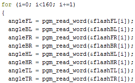
Figure 4: Active control circuit for Dynamic walk

Spring 2016 Velociraptor: Spring Experiment

By: Mingyu Seo (Manufacturing & Design Engineer)

Introduction:

After assembling the final prototype and testing the static walk, we’ve found the weight of the head and tail were straining the servos. We’ve decided to use a spring to support the weight, which lead us to perform a quick experiment to see how much the spring will help support the weight. A variety of miscellaneous items were use as mass to test the spring constants.

Procedure:

s3

Figure 1. Experiment procedure

Figure 1. shows the experimental procedure to test the spring. We’ve added weight to see the extension of the spring, and to see how much the spring will be able to support with maximum of 300 grams due to our head and tail only weights 200 grams with the battery included.


s2

Figure 2. Experimental Data


s1

Figure 3. Attached spring to the head of the robot.

Conclusion:

By adding a spring we were able to reduce majority of the stress applying to the servos. By removing the stress on the servos we also conclude that it reduces the power intake of the servos because the servos no longer hold the full weight of the head and tail. To see how much power is consume refer to the servo load test blog post.

Spring 2016 Velociraptor: 3D Smoothing

By: Mingyu Seo (Manufacturing & Design)

Introduction:

In order to accommodate mass budget of the robot, our team has decided to create the legs and the top using 3D filament polylactic acid (PLA). One of the drawbacks of using 3D printing method is the result of the prints having ridged surface texture created by the layer by layer printing. There are multiple solutions for smoothing surface of PLA 3D prints to make the final product better. We will be looking at 2 methods that are safe and simple to apply.

3D printer setting:

Layer height (mm): 0.25

Shell thickness (mm): 1.2

Bottom/Top thickness (mm): 1.0

Fill Density (%): 25

(Leg Picture here)

The picture shows the one of the finished print for the right leg, which we could clearly see the ridged surface texture.

Smoothing Methods:

  1. Acetone Bath
  • Acetone bath is one of the most commonly used method to smooth out PLA and ABS materials. It melts the outer plastic and creates a smoother and glossy looking surface. Acetone bath is the simplest and fastest method to smoothing 3D materials.

Procedure:

  • (Optional) Sand the 3D material using sandpaper (P320 most optimal) to smooth out the ridged surface.
  • Pour enough acetone in a container (Just enough to fully submerge the part)
  • Keep the part submerged for 40 ~ 60 seconds
  • Take it out and dry.

(*CAUTION: make sure to use gloves when handling PLA due to melted plastic)

2.  XTC-3D epoxy

  • XTC-3D epoxy has lately been getting attention in 3D community which uses 2 liquids that are mixed together and then brushed onto 3D prints. Due to XTC-3D is a protective coating that does not melt plastic, so sanding all parts before applying is highly recommended.

Procedure:

  • sand all surfaces of the 3D parts using P320 or P600 sandpaper.
    • starting off with P600 may be a safer option,
  • Apply coating on to 3D parts using a brush.
  • Dry for minimum 4 hours.

XTC-3D coating works with all 3D materials as well as wood, plaster, fabric, cardboard, and paper. It’s easy to apply but takes a long time to dry. It takes minimum 4 hours and may need to be applied several times to have a unified smooth surface.


Conclusion:

To decrease production time, our team has decided to incorporate acetone bath to our final product. Program Level 1 Requirement 1 states the Velociraptor biped robot shall demonstrate its feasibility as a toy. To fulfill this requirement, acetone bath will not only help to smooth out the rigged surface but also improve the look of the final product.

Spring 2016 Velociraptor: Hardware &Simulation

By: Mingyu Seo (Manufacturing &Design)

Introduction:

The purpose of this blog is to show the feasibility of the design we’re going to incorporate in to our robot. Using Solidworks, we’ll be able to validate center of mass of the robot when we’re performing static walking. Also by using the simulation on Solidworks, it’ll show the basic motion of the robot walking. Following hardware design will explain the problems and solutions we’ve made to find the most suitable design of Velociraptor.

Requirements:

Project Level 1:

  1. Requirement 1 states the Velociraptor shall resemble a Tyrannosaurus class of dinosaurs as given in the objective.
  2. Requirement 2 states the word “biped” is defined as having two feet; therefore, the Velociraptor shall use two legs to move.
  3. Requirement 4 states the Velociraptor shall be able to statically walk on all surfaces of the course
  4. Requirement 5 states the Velociraptor shall be able to dynamically walk on flat surfaces of the course.

Project Level 2:

  1. Requirement 4 states to resemble a Tyrannosaurus class of dinosaurs, the chassis of the Velociraptor shall be cut out in hollow body parts to assemble a frame-like body structure in a material that is cost effective
  2. Requirement 6 states to maintain balance while performing static walking, a head and tail shall be implemented to the chassis of the Velociraptor

Overall, the design of the robot must resemble a Tyrannosaurus class dinosaur, that walks on two legs, and by incorporating the head and tail will help keeping the robot balanced when it’s performing static & dynamic walk by shifting the center of mass using the weight of the head and tail. New designs were incorporated in to our new design to accommodate mass, price, and power budget.

Hardware Design:

1.1

Figure 1. Final Design of Velociraptor (excluding sensors)


2 (2)

Figure 2. Exploited View of Velociraptor

First Design:

right leg

Figure 3. First design of the joint

Figure 3. shows the first design of the joint which incorporates the 3rd joint that was missing from the previous generation. The new design also incorporates a new design of the ankle where it’s connected with 2 parts rather than 1 that holds the leg and the foot, which helps the foot to stay parallel to the surface at all times.

Problem: when assembling the first design, we had few design problems

  1. The 3D printed parts were not sturdy
    1. Not strong enough to hold up the weight of the body
    2. putting too much pressure on the base of the foot started bending parts.

Second Design:

kinda new right leg

Figure 4. 2nd Design of the joint

Figure 4. incorporates the fixed design of our first design. We made all our parts minimum 0.3 cm thickness to prevent our parts from bending. The front joint that connects from front servo to the knee has thickness of 1.2 cm to have a more stable stance, and make sure it’s sturdy enough to hold the weight of the robot.

Problem:

  1. By increasing the thickness of the joints also increased the angle the head and tail must turn in order to shift the center of mass when performing static walk.
  2. When designing the 3D model, the design did not compensate the extra length added due to servo caps.
  3. The thickness of the foot was still too thin.

Final Design:

New right leg

Figure 5. Final Design of the joint

Figure 5. shows the finalized design of the leg of Velociraptor.

Final Features:

  1. Shifted the front top joint (connecting from front servo to the knee) to the out in order help the robot to find center of mass by moving the head and tail less.
  2. Also have incorporated the placement for the servo caps to bring it closer to the center.
  3. All parts have minimum 0.3 cm to have a stable stance when it’s performing static walking.
  4. Extra length toward the back and outer side of the foot to have a more stable and balanced walking.

PCB placement:

First when we were designing the robot, we have decided to place all the sensors and the pcb underneath the servos. After finishing our PCB layout, we have found the size of the board too big to be placed under and due to the size of the voltage regulator it was not applicable to fit all the components under the robot. In order to solve this problem, we have decided to create a clear casing on top of the robot and place all our components in.

Design Features:

  1. Bottom of the case have been cut out in order to bring the wires underneath and hide it.
  2. hole has been placed on the front side of the casing to place the ultrasonic sensor.
  3. casing will be made with a clear PLA filament to show the components inside.
pcb placement

pcb placement2 Figure 1. Design of the casing to hold up the PCB and also the top view of the casing


Simulation:

The simulation below shows the motion of the Velociraptor when it’s performing static walking.

In order to balance on one foot, we need  to move the center of mass above the supporting leg by moving the head and tail toward the supporting leg for counter weight.

ezgif.com-video-to-gif

Conclusion:

This simulation shows the given dimension of the 3D model shows the feasibility of the design of the Velociraptor, and confirms the level 1 requirement 4, which states the Velociraptor being able to statically walk across the full course. The design that we have incorporated have been tested and resulted as successful when we’ve performed static walking. Biggest issue was trying to keep all wires and components hidden but due to the size of the PCB and the size of the voltage regulator heatsink we have decided to mount it on the top of the robot. The Head, Tail, and bottom plate for the robot was made with Aluminum, but the legs, top plate, and the PCB casing will be printed using PLA filament.

Spring 2016 Velociraptor: Critical Design Review Debrief

By: Khoi Vu (Project Manager)


The Critical Design Review (CDR) purpose is to present data and progress of the project to the President and the Customers. The CDR presents the executive summary, system and software design, experimental results, interface definition, and the custom PCB design that will be used on the final product.


For full PPT of CDR click on the link below:

https://www.dropbox.com/s/c61ju4onj17a5zi/CDR.pdf?dl=0


Debrief:

  1. In the executive summary, there should be an exploded view of the 3D model of the product that contains the name of the person responsible for each slide.
  2. Executive summary should always be short, summarizing the project design and design features.
  3. System design should not show the PCB.
  4. Servos tests in the experimental result were done incorrectly; a stick lever arm was used as lever length changes during rotation. A circular lever arm will give a more accurate result because it will have a consistent radius.
  5. Incline testings did not show how the robot will respond to the incline when it is walking sideways on the incline instead of walking up the incline.
  6. Power test did not give a accurate result of power consumption by the servos, a ammeter should be used to connect in series to find the actual power consumed by the robot since the robot has been completely assembled.
  7. PCB schematic was not presented clearly; a white background with black lines would be much easier to see.
  8. Since the robot is taking in a lot of Current (5 Amp), a fuse is recommended to protect the components of the robot.
  9. Active Control Circuit is missing for the dynamic walking requirement. The team should still acknowledge all requirements that have been listed.
  10. The team should consider how the robot’s foot should always be parallel to the ground and not always the x-axis. This may cause failure when walking over obstacles and inclines.
  11. Verification and Validation tests needs to show more results.
  12. Resource report values that were measured should not contain any uncertainty since the values were measured and not estimated.
  13. Cost Budget should also contain the cost of parts that were donated to show a more accurate cost of the whole project.
  14. Final printing should not start when PCB size is not known yet.

Note:

Number 5 was tested and the results were shown in CDR PPT,  however, the team may have not discussed the results in depth.

Number 14 printing only consist of parts such as the legs that have been enclosure, the team have not finalize the design for the PCB container, therefore, we have not printed the PCB case.


Spring 2016 Velociraptor: PCB layout

By: Mingyu Seo (Manufacturing & Design)

PCB Design:

For our design, we’ve started off by planning where our PCB is going to be mounted. Rather than placing it on top or inside the body frame, we’ve come up with mounting the PCB underneath the body to cover wires connecting all the components together. So, we have decided to mount the Arduino Micro as well as the accelerometer in order to minimize the number of wires connecting to the PCB. We decided to wire the Bluetooth toward the tail and the accelerometer on top to make sure it’ll be able to detect obstacles ahead.

Problems:

  1. The voltage regulator may cause too much heat.
  2. Minimum space to place all components
  3. Sensors mounted directly to the board must either be mounted so that they hang off the edge of the PCB, or the packages must be edited to include the physical shape of the device to avoid overlap of components.

Solutions:

  1. we will be using thru-hole heatsink method rather than PCB copper heatsink. Also by placing the voltage regulator to the corner, we will be using TO-220 Heatsink. 
  2. Due to very little space provided for PCB layout, we will have to make sure to place the power supply as far away from the Bluetooth, accelerometer, and ultrasonic sensors as possible.
  3. we have a 5.12cm x 4.8 cm PCB layout, which must incorporate Arduino Micro, Accelerometer, Bluetooth, ultrasonic sensor, 8 Servos. By placing all the sensors on one side, we will be able to mount the accelerometer off the edge of the PCB, and connect Bluetooth and ultrasonic sensor with a wire.


PCB Layout:

PCB layout FINAL 2

Finalized PCB layout

PCB layout FINAL

Finalized PCB layout Wiring


Spring 2016 Velociraptor: Material Trade-Off-Study Update

Requirements needed to fulfill:

  • Project Level 1 Requirement:
  1. According to the given course that the robot is to complete, the Velociraptor shall travel on multiple surfaces. Refer to course analysis for more detail.
  2. The Velociraptor shall be able to statically walk on all surfaces of the course
  3. The Velociraptor shall be able to dynamically walk on flat surfaces of the course.
  4. The Robot shall statically travel up a 6.5-degree incline according to the course analysis
  • Project Level 2 Requirement:

6. To maintain balance while performing static walking, a head and tail shall be implemented to the chassis of the           Velociraptor to even out the shifted weight when standing on one leg and           thus meet the Project Level 1, requirement

8. In order for the Velociraptor to travel on two different surfaces, the material that will be placed on the feet shall           have a coefficient of friction of more than 1.0 in accordance to the                      Course Analysis as to refrain from slipping,               and thus meet Project Level 1, requirement 3.

Actual experiments will be done to verify the feasibility of the design using our 2nd prototype.

Experiments:

  1. Material Trade – Off- Study:

a) First Experiment included the feasibility of using 3D filament Polylatic Acid (PLA) for our final robot. When we started building our 2nd prototype, including the head and tail, we’ve decided to distribute the weight of the body by placing the batteries toward the head and tail to put less strain on the servos. By using this design, we will be able to minimize weight of the chassis of the robot and use the weight of the head and tail to shift center of mass.

prototype

But putting more weight toward the head and tail, caused the bottom piece of the body that connects the head to start cracking which made us do a material trade-off-study to determine the right material for our robot.


material1

Trial using PLA filament


material2

Trial using Aluminum


The printing the bottom piece using the 3D filament weighed 13 grams compared to Aluminum piece which weighed 19 grams. This not only shows the feasibility of using Aluminum for our bottom piece to maximize the weight on the head and tail, verifying project level 2 requirement 6 to implement head and tail on the chassis to shift the center of mass to balance when it’s performing static walking.


b) The second experiment was conducted in order to verify the 3D filament PLA is feasible perform static and dynamic walking on various surfaces without slipping.

Level 1 requirement 6 states the robot should perform static walking on a 6.5 degree incline, so we’ve created inclines using various degrees to determine if the robot was able to balance and refrain from slipping at a minimum of 6.5 degrees. For our experiment, we started off by creating a slope from 4.5 degrees to 13.7 degrees and tested to determine the degree the robot starts slipping.  In order to create a similar static friction of the course, we have implemented a carpet on the incline. For experimental measurement, we’ve used a protractor to measure the angle of the slope, and for the theoretical measurement, we’ve used the length and height to calculate the slope:

inlcine

Both feet on Ground:

friction test chart 1

The chart above shows the acceptability of the 3D model, when we assembled the robot, it was able to stand with both foot on the ground up to 15.7 degrees without slipping or falling.

Figure 3b

Placed sideways on a 8.7 degrees incline, successfully balancing and refraining from slipping.

Figure 3a

Robot placed on a 8.7 degrees incline without slipping or falling.


One foot on Ground:


friction test chart 2

When the robot is performing static walk on incline, we’ve tested if it was able to balance on one foot without falling or slipping. As shown above, the experiment showed the robot was able to balance on one foot up to 9.7 degrees incline.

OLU 3a

By shifting the weight of head and tail toward the shifting leg, the robot is able to stand on one foot as if it’s performing static walk. It’s able to stand on a 8.7 degrees incline without slipping nor falling.


Conclusion

Using a thicker material for the bottom piece will not only increase printing time, but also create less space for our components to fit. But by using Aluminum for the bottom piece of the body to hold the head and tail, not only will it be able to hold up to 483 grams but also we will be able to keep enough space in the middle to mount the PCB. The test to verify the material used to refrain the robot from slipping have been successful. The robot was able to stand on both feet and on one foot up to 9.7 degrees without slipping. When the robot has to stand on an incline of more than 10 degrees, we will have to reconfigure the robot’s ideal standing position to slightly lean forward in order to make sure the center of mass stays in the middle of the robot’s body.

Spring 2016 Velociraptor: Updated Walking Code #2 (Flash Memory)

By: Ashlee Chang (E&C)

Table of Contents

Fulfilling Requirements

Level 1 requirements #4 is stated as follows:

The Velociraptor shall be able to statically walk on all surfaces of the course.

Level 2 requirements #10 is stated as follows:

An ultrasonic sensor shall be implemented to the build of the robot to detect obstacles at a range of 20 cm.

The Arduino software, which uses much of C++ programming language, will be used to construct and upload the code onto the Arduino microcontroller. The MB1030 ultrasonic sensor was implemented in this updated code.

SRAM Limitations

a

Arduino memory sizes

Looking at the Arduino micro specifications as listed on their website, it’s noted the SRAM (static random-access memory) memory is a mere 2.5 kB compared to flash memory at 28 kB (taking into account the bootloader space). The previous walking code could potentially “blow up” the microprocessor using while condition loops and many variables. To avoid this problem, moving the servo angles to flash memory is not only vital, but proved to be more convenient.

The How-To

The first step is to transfer all servo angles over to an excel spreadsheet. It is important that in each column, all of these angles should be designed to be read at the same time. For example, in column 1, we see that front left = 110, black left = 70, front right = 92, etc. That means that at this point of time of 0 seconds, all servos will read at these respective angles. These indexes are related to the time the velociraptor is operating at. The velociraptor has 160 cells for each servo. The whole point of using excel is to better organize the angles and ensure that every servo has the same number of total indexes. For the second prototype, the new legs had different dimensions, thus some adjustments were required for the servo angles.

aaaa

Servos and their servo angles

Next, save this excel file as .CSV. Re-open this file, but this time using notepad.

xxxxxxx

.CSV file opened in notepad

Now it is easy to grab these angles separated by commas and insert them into an array to be stored in flash memory. Next, on the right-hand side of the Arduino software, there is a down arrow button. Click this to expand some options, and click New Tab. Name this file according to the particular servo, and end the file name with “.h” to ensure it will in fact be an h-file. For example, one .h file the velociraptor used was flashFL.h (FL for front left servo).

asdf

Next, add “const unsigned int _[] PROGMEM = {_};” in this new .h file tab. The first _ will be the name of your .h file. The second _ will be the array copied and pasted from the .CSV file opened with notepad for the associated servo angle array. The command PROGMEM stores data in flash memory as opposed to SRAM memory.

123

Using PROGMEM in the .h file

All of these .h files should be in the same folder as the main code. Double check this, else the main code will not know where to look for these files. The .CSV file is not necessary to keep in the main folder, but is easy to refer back to in case any changes are to be made.

asdfd

.h files in the main code folder

To allow the main code to utilize these arrays stored in flash, “#include_” must be stated in the beginning of the main code.

1343223

#include for the .h files

Last but not least, the array values are called from flash memory based on its index value. Use the function pgm_read_word(&_[i]); to access this data.

12321321

Reading from flash memory using indexes

Updated Walking Code

Below is the updated walking code.

WalkFLASH_ultrasonic

Note how much cleaner and shorter the code is compared to using dozens of while loops to control the eight servos of the velociraptor.

dddd

Updated walking code using flash memory

The main loop reads from all of the servo .h file arrays at one index at a time, then written to all eight servos at the same time. There are a total of 160 indexes per file, so after 160 iterations, the velociraptor will have taken two steps (one with each leg). Moving to flash memory not only saves SRAM memory, but also makes editing any servo angle at any point of time a piece of cake. A delay of 20 ms was chosen, but this could be adjusted to make the velociraptor walk slower or faster.

Also updated for the CDR presentation was implementation of the ultrasonic sensor. Every 40 cells read from the servos, there would be an object detection check. If there is an object within 10 inches of the ultrasonic sensor, the velociraptor would stop.

Also new to the code is the newly added head and tail. In order for the velociraptor to take a step, the center of mass must be moved from the center body to directly on top of the leg that will still be on the floor. Below is a table explaining the 160 cells of each array. For the first 40 cells, the left leg will take a step. This means the head and tail are already turned to the right so that all of the velociraptor weight is on the right leg that is on the floor. For the next 40 cells, both legs are on the floor as the servos both reinitialize in reparation for the next step while propelling the body forward. Because both legs are on the floor, the head and tail can now move from right to left. Etc.

rtrgr

Implementing the head and tail

Spring 2016 Velociraptor: Circuit Schematic & Servo Load Test

By: Ashlee Chang (E&C)

Table of Contents

A Clean Electronic Setup

breadboard

Breadboard testing

The electronics journey goes as so: Fritzing diagram, breadboard testing, circuit schematic, and then PCB (printed circuit board) fabrication. All electronic components are Arduino microcontroller, four batteries, eight servos, Bluetooth, ultrasonic sensor, and accelerometer. Notably, there are quite a bit of components, meaning a lot of wires needed to interface between them all. That is why the team decided that most of the wiring would be implemented on the PCB to avoid a messy project. Also, the microcontroller will be mounted directly on the PCB for this very purpose.

Servo Load Test

Servos in general draw quite a sum of current, and that current draw is proportional to the load (weight) the arm has to push against. A voltage regulator will be needed for the velociraptor, so it’s essential to see approximately how much current is drawn by these powerful servos so an appropriate regulator can be chosen. A test was conducted to see the servo load versus current draw.

xx

Servo load and current test

A bucket containing miscellaneous materials to reach a particular weight was used and weighed on a scale. Afterwards, a string was used on the bucket and attached to the servo. A simple sweep code was installed on the servo to work against this load. An ammeter was inserted into the servo and power source loop.

xxx

Servo load and current results

The results were documented in the above table. The velociraptor currently weighs 544g (not taking into account the PCB, microcontroller, sensors, and Bluetooth). Thus, the project will weigh around a total 570g-600g. Taking the current draw of 0.3A at 506g from the table, this brings the current draw of eight servos at 2.4A. If the project is estimated to be 600g, the total current draw should be close to 3A, not taking into account current going to other parts of the circuit. Thus, the voltage regulator must be capable of handling over 3A.

Voltage Regulator

The voltage regulator is the only major component on the circuit schematic. Choosing a proper one was difficult. A decision between an LDO (low dropout voltage) voltage regulator versus switching regulator was contemplated. The switching regulator is actually highly efficient compared to the LDO voltage regulator. The lesser the inefficiencies, the lower amount of energy will be wasted as heat. Because the velociraptor shall be designed as a child’s toy, hot electrical pieces is a definite no-no that must be avoided for the health and safety of the user. With all switching regulators, there needs an inductor in the suggested schematic, which requires specific placement of the schematic in terms of distance on the PCB. Finding a switching regulator with an internal inductor proved to be impossible. In addition, there are not many switching regulators capable of stepping down small voltages. In the velociraptor’s case, the voltage had to be stepped down from 7.4V to 6.0V, which is only a change of 1.4V. Due to the complexity of switching regulators, the team decided on an LDO voltage regulator.

Some spec considerations that must be taken into account were: 5A maximum current output, input of 7.4V, output of 6V, capable of stepping down 1.4V, efficient, and through-hole (the smaller the package size, the hotter the component can get). The voltage regulator agreed on was MIC29512. Some additional features include current limiting protection, thermal shutdown, and an enable input pin that can be used to turn off the voltage regulator when not in use.

x

MIC29512 Voltage Regulator

Heat Sink

If the voltage regulator were to be a surface mounted piece, some copper embedding must be implemented. However, seeing the voltage regulator is a through-hole TO-220 package, a screw on heat sink can be used. For calculations based on the datasheet, the math is as follows: Rtsa = [125 – 50] C / 3W – 2 C/W – 1 C/W = 22 C/W. Any heat sink under 20 C/W would be ideal, but one with a specification of 9.6 C/W was chosen because, after all, this is a child’s toy.

xxxx

Heat sink choice

Eagle Circuit Schematic

schematicfinal

Velociraptor circuit schematic

The final circuit schematic is shown above. Both two batteries will be in series, and those two are in parallel. The resistors in between are used to help with any possible offset in between the two battery pairs. Transistors were placed to use the enable pin. A large capacitor needs to be next to the batteries. A TO-220 package was made for the schematic, and the recommended schematic was constructed based on the MIC29512 datasheet. The respective resistors used were calculated to output 6V on the voltage regulator. The batteries were connected to both the microcontroller (which can take inputs up to 12V) and the voltage regulator. The regulator feeds the servos as to get to that optimal voltage of 6V. The Arduino micro is placed directly in the schematic. Lastly, some simple connectors were used for the sensors, actuators, and Bluetooth.

Spring 2016 Velociraptor: Center of Mass

By: Mingyu Seo (M&D)

Introduction:

Humans use center of mass to balance, for example when we are standing on both feet our center of mass would be at the center of our body, but when we try to position or balance on one foot, we shift our body closer to the supporting leg which also shifts our center of mass to find balance. Our team has incorporated this idea to our robot in order to successfully perform both static and dynamic walking. Solidworks can calculate the center of mass and the total mass of our 3D model based on the design and dimension created by the Manufacturing & Design Engineer. Our level 1 requirement shows the robot should be able to complete the course using both static and dynamic walking. In order to successfully complete a static walk, the robot should be able to balance itself on one leg while the other leg takes a step forward. When we’re lifting one leg up it is very important for the center of mass to be as close to the most supported leg to maintain balance.

Method:

Solidworks can calculate the center of mass by simply changing the position of our robot. When we are performing a static walk, we will lift one leg up and use our head and tail as a counter mass to bring the center of mass closer to the supporting leg. The pictures shown below will explain how the center of mass shifts when the robot takes a step.


Screen Shot 2016-04-02 at 6.48.00 PM

Figure 1: Standing on both feet

Screen Shot 2016-04-02 at 6.48.10 PM

Figure 2: Lifting right leg

Screen Shot 2016-04-02 at 6.48.20 PM

Figure 3: Lifting left leg

Figure 1. Shows, when the robot is standing on both feet, we could see that the center of mass (pink dot) is position right in between the two feet. Figure 2. Shows when we lift our right foot, we position our head and tail left in order to create a counterweight for our center of mass to be closer to the supporting leg (left leg). Lastly, Figure 3. Shows when the left foot is up, we would position our head and tail to swing right to move our center of mass closer to the right foot. Figure 2. & Figure 3. Shows that the center of mass hasn’t reached fully above the supporting leg, but this error was caused by the insufficient weight of the head and tail. Our design includes distributing our battery between the head and tail in order to minimize weight load on our body as well as create enough counter weight for our robot to perform static and dynamic walk. For 2016 Velociraptor team, Center of mass testing using Solidworks have helped to validate our Level 2 Requirement (#6) of maintaining balance while performing static walk.