Velociraptor Team:
Khoi Vu (Project Manager)
Camilla Jensen (Systems Engineer)
Ashlee Chang(Electronics & Control Engineer)
Mingyu Seo (Design & Manufacturing Engineer)
Program Objectives/Mission Profile
By: PM Khoi Vu
The Spring 2015 Velociraptor biped was inspired by the robot Titrus-III; it was designed and created by Tokyo Institute of Technology. The purpose of this project is to design a Tyrannosaurus class biped robot to be used as a toy. The mission profile is to demonstrate the feasibility of the dinosaur biped as toy product. The objective of this project focuses on a toy with the ability to detect and avoid obstacles. The Velociraptor will be controlled by establishing a communication with the Arxterra Android application.
Requirements
Program/Project:
The requirements are divided into two categories, program and project. The program requirements are general requirements that the robot must fulfill, whereas project requirements are more specific to the appearance and ability of the robot. To ensure the success of this project, these requirements were set based on the customer’s objectives and mission profile.
Program Level 1 Requirement:
- According to the CSULB 2015-16 Academic Calendar, the Velociraptor biped shall demonstrate its feasibility as a toy by Monday, May 9, 2015 (Last Day of EE400D).
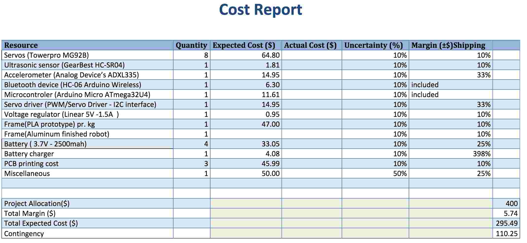
- The Velociraptor’s biped shall cost no more than $400.00. This limit was determined by analysis of the previous project estimated and the final cost of Fall 2015 MicroBiped, and Spring 2015 MicroBiped.
- The project shall follow the CSULB College of Engineering Health and Safety Policy before the Velociraptor can be demonstrated at CSULB.
Project Level 1 Requirements:
- The Velociraptor shall resemble a Tyrannosaurus class of dinosaurs as given in the objective.
- The word “biped” is defined as having two feet; therefore, the Velociraptor shall use two legs to move.
- According to the given course that the robot is to complete, the Velociraptor shall travel on multiple surfaces. Refer to course analysis for more detail.
- The Velociraptor shall be able to statically walk on all surfaces of the course
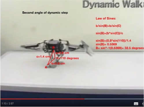
- The Velociraptor shall be able to dynamically walk on flat surfaces of the course.
- The Robot shall statically travel up a 6.5-degree incline according to the course analysis.
- The Robot shall have the ability to detect obstacles in its path.
- The robot shall make turns when an obstacle is detected and shall maneuver around the detected obstacles.
- The robot shall be controlled via Bluetooth communication with the Arxterra Android application.
- The Velociraptor shall be power using a portable power source.
System/Subsystem Requirements
Project Level 2 Requirements – Systems requirements
By: S&T Camilla Jensen
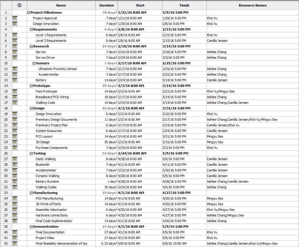
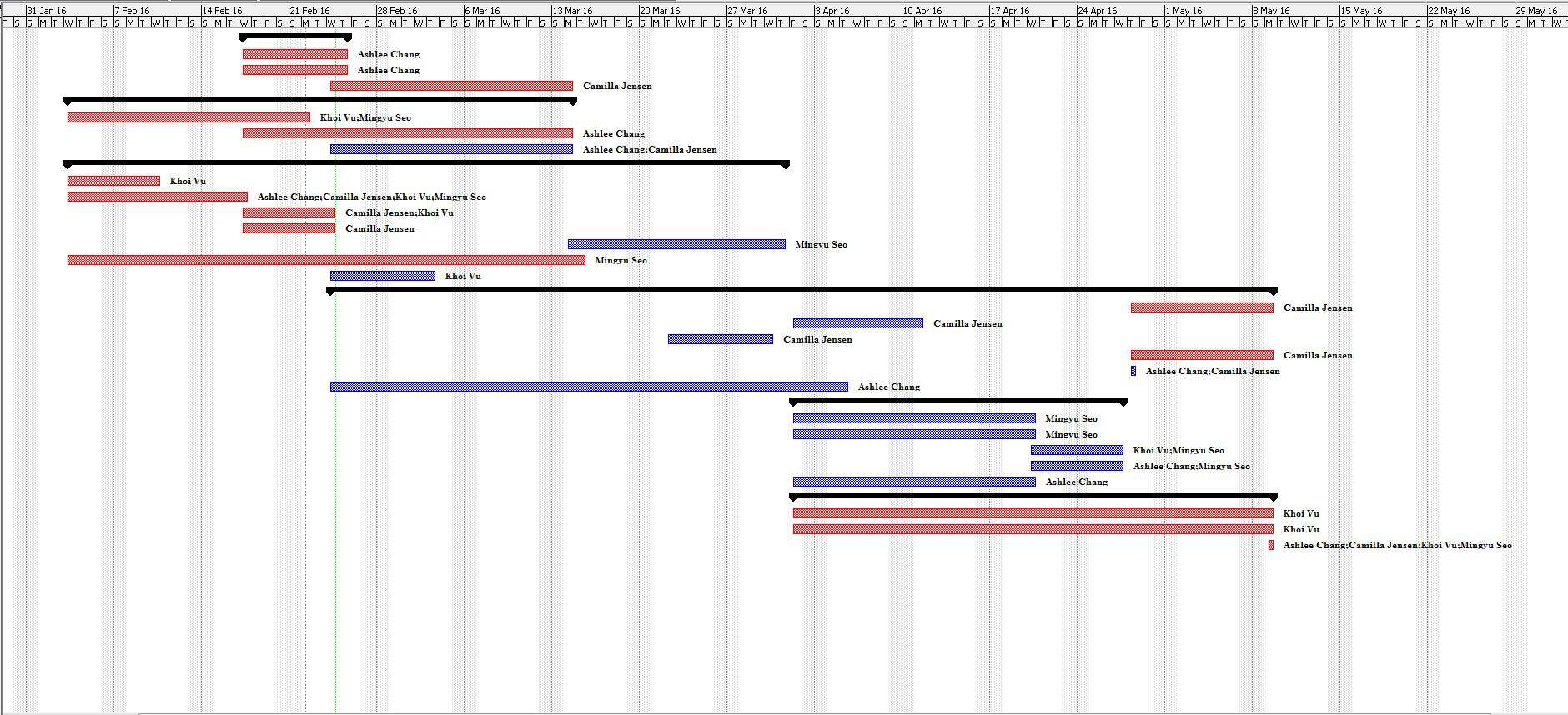
- According to the CSULB 2015-16 Academic Calendar, all the subsystems of the Velociraptor biped shall stay within the time phasing to complete project Velociraptor by due date Monday, May 9, 2015 (Last Day of EE400D) and thus meeting the Level 1, requirement 1.
- To have a realizable budget, the chassis shall be manufactured directly at CSULB and thus meeting the Level 1, requirement
- In order for the project to meet the CSULB College of Engineering Health and Safety Policy, all project members shall read through and become thoroughly familiar with the policy and accordingly comply with the policy and working in a lab, and thus meeting the Level 1, requirement 3.
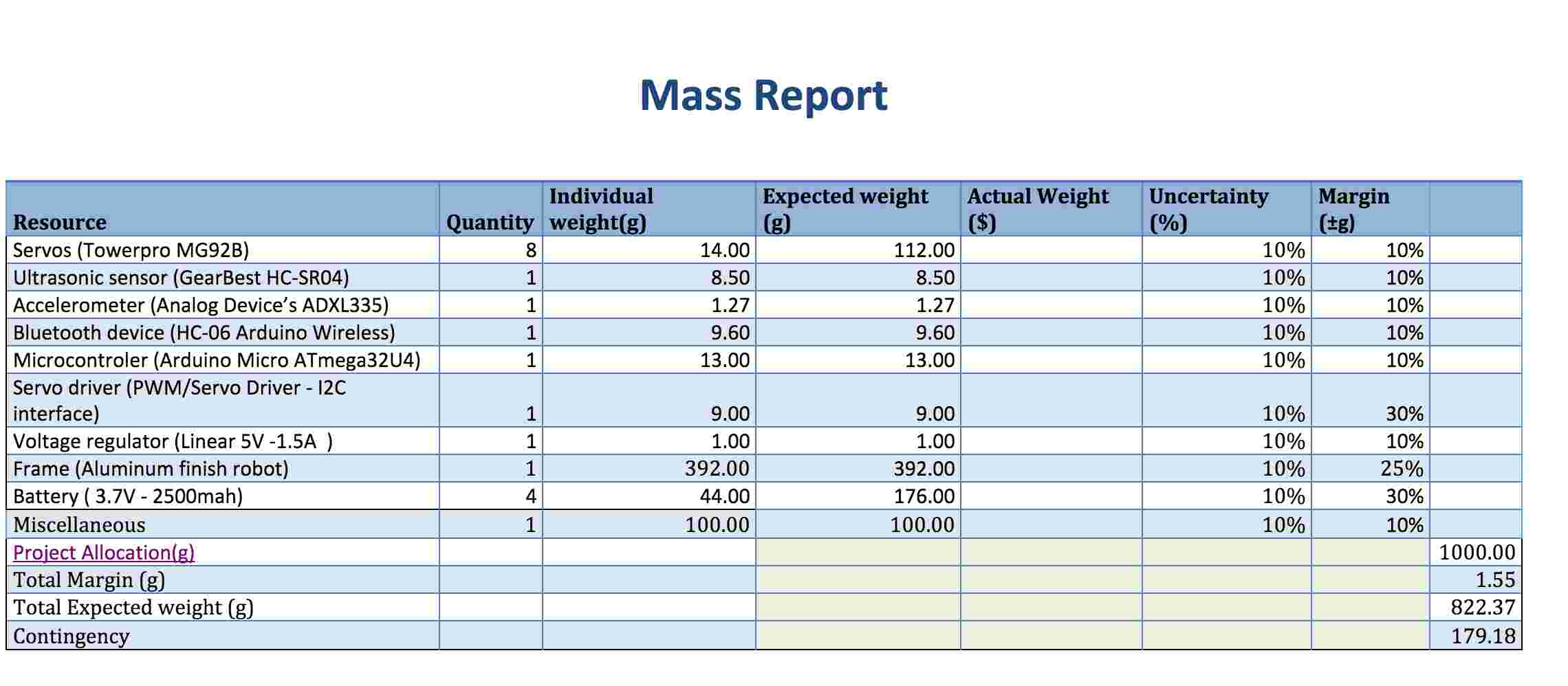
- To resemble a Tyrannosaurus class of dinosaurs, the chassis of the Velociraptor shall be cut out in hollow body parts to assemble a frame-like body structure in a material that is cost effective i.e. Stays within budget (Cost report) and sturdy enough to carry weight of Velociraptor (mass report) and thus meeting the Project Level 1, requirement 1.
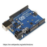
- To facilitate the algorithmic functions of a Velociraptor Biped, an Arduino Microcontroller shall be implemented as the brain of the Velociraptor and thus meeting the Level 1, requirement 5.
- To maintain balance while performing static walking, a head and tail shall be implemented to the chassis of the Velociraptor to even out the shifted weight when standing on one leg and thus meet the Project Level 1, requirement 4. [6]
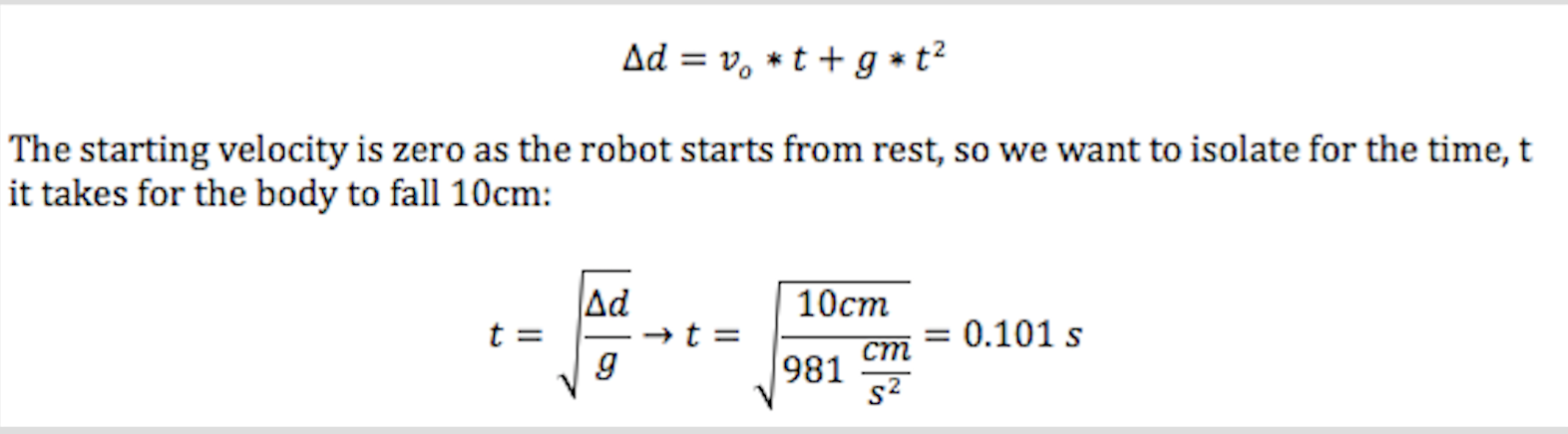
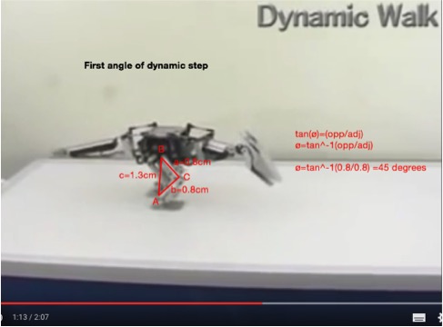
- For the Velociraptor to perform dynamic walking servos moving at a speed of 0.101 sec/12.5° shall be implemented to the chassis and thus meet the Project Level 1, requirement 5. [7]
- In order for the Velociraptor to travel on two different surfaces, the material that will be placed on the feet shall have a coefficient of friction of more than 1.0 in accordance to the Course Analysis as to refrain from slipping, and thus meet Project Level 1, requirement 3. [8]
- For the Velociraptor to have the ability to travel up a 7-degree incline, an accelerometer shall be implemented to preserve the chassis balance and thus meeting the Level 1, requirement 9.
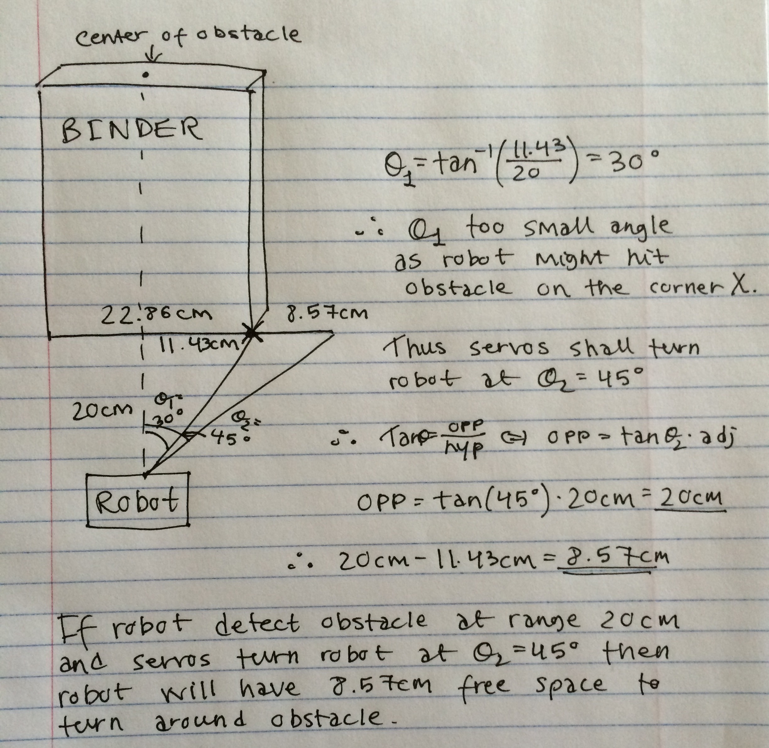
- In order for the robot to detect obstacles at a range of 20 cm in its path, ultrasonic sensors shall be implemented to the build of the Velociraptor and thus meeting the Project Level 1, requirement 7. [10]
- To fully accommodate the movement of a turn, a total amount of 8 servos turning the robot at a an angle of min. 45 ° degrees(referring back to requirement 10) to avoid obstacles shall be implemented to the Velociraptor and thus meeting the Project Level 1, requirement 8.[11]
- In order to control the Velociraptor remotely, the Arxterra application for Android phone shall be implemented to the robot and thus meet Project Level 1, requirement 9.
- To establish the wireless connection between the Arxterra Application and the Velociraptor in order to control the robot a Bluetooth communication shall be executed into the system’s robot design to meet Project Level 1, requirement 9.
- In order to control the Velociraptor wirelessly, a battery shall be implemented to power the robot for a minimum of 60 minutes and supply power enough for the MCU and servos TBD in the power report to meet Project Level 1, requirement 10.
Design Innovation
By: PM Khoi Vu, E&C Ashlee Chang
Brainstorming Approach: Flaws of Previous Generation:
- Size & Weight: In the previous generation of MicroBiped, solid printing of parts made the robot heavier than necessary. The material used also contributed to the weight of the robot.
- Center of Mass: The head and tail did not counter the mass of the body. This caused the center of mass to not be supported by the foot for the essential balance of the robot.
- Servos: Did not provide enough torque to turn the head and tails of the MicroBiped. This flaw will be further explained in the next part.
- Joints: The weight of the head and tail of Fall 2015 MicroBiped was supported by the servos.Servos are not designed to support weight but rather provides torque to the system. The leg of MicroBiped was also missing a joint that may have prevented it from walking.
Attribute Listing: Possibility for the Next Generation Biped
There are many different attributes to focus on in design such as material, input devices, color, size, shape, taste, texture, hardness, and odor. Some of the few focused on for the velociraptor are listed below.
- Wood: Khoi has access to a woodshop. Using wood, we can manufacture parts of the body perhaps for a prototype. It would be difficult to implement wood on the final design of the velociraptor, as hollowing would be tedious and inaccurate.
- Metal: Metal is easier to work with and to manufacture. Using light metals such as aluminum could solve the weight issue from last semester’s MicroBiPed.
- Electroencephalogram: An EEG would definitely make the customer happier with a “cooler” design, but this remote was not easy to control. Brainwaves proved to be an inaccurate input method for the velociraptor.
- Arxterra Control Panel: Most projects in the Robotics Company plan to use the Arxterra app as a remote for communication. This option has a lot less wow-factor, but will, in fact, communicate successfully having reliable Bluetooth.
- Distribution: Weight distribution must be mapped out as to keep the velociraptor balanced. For instance, the head and tail of the velociraptor must contain a chunk of the overall weight to balance out the displacement of the left and right foot.
- Material: Choice of material for the velociraptor can determine the success or failure for the velociraptor to perform. The material must be light enough to meet the servos torque requirements.
- Components: Each electrical component adds more weight to the overall project. Trade-off tables must list important parameters comparing weight to other parameter ratios.
Lateral Thinking:
- Forced Relationship Technique:
- A biped that fly.
- A biped with wheels.
- A biped made of paper.
- A biped that will be able to travel at lightspeed.
- A biped that will be able to swim.
- A biped that will walk using its arm and play basketball.
Solutions:
- Size & Weight: Reduce mass by printing out hollow parts and using better material for printing that may be lighter than what was used the previous generation.
- Center of Mass: Increase mass of head and tail or move head and tail further away from the body to better balance the weight on the foot
- Servos: Upgrade to servos with more torque and faster turning speed for easier maneuvering and to complete dynamic walking requirement.
- Joints: New joints will be designed for the head and tail to distribute the weight to the body instead of the servos. The missing joint will be included to ensure the stability of the robot.
Systems/Subsystem Design
By: S&T Camilla Jensen
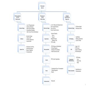
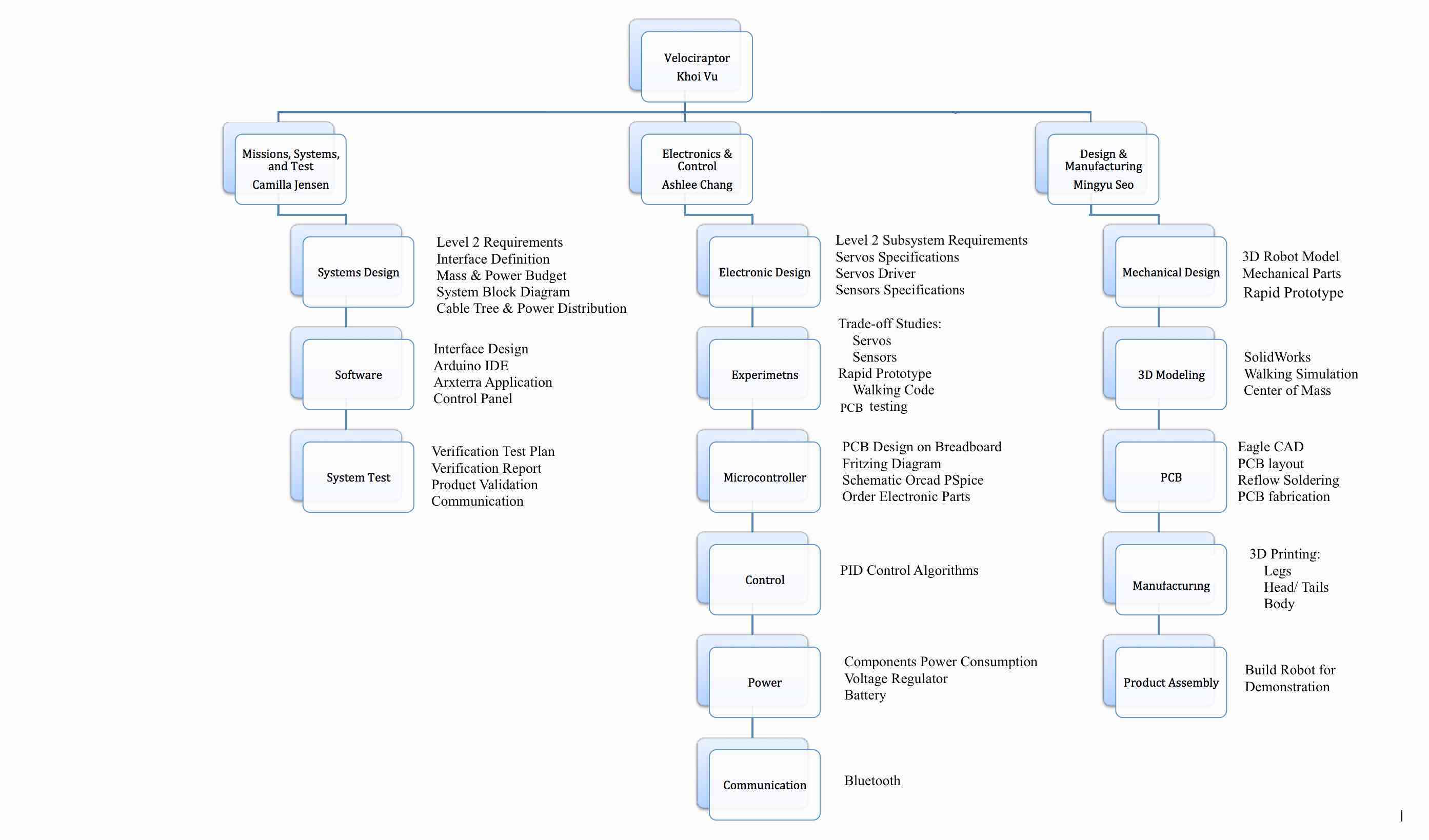
Product Breakdown Structure
Power
The Velociraptor will have power supplied from a portable source, such as a battery so that it can be controlled remotely from the Arxterra application on an Android phone.
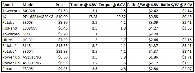
Servos
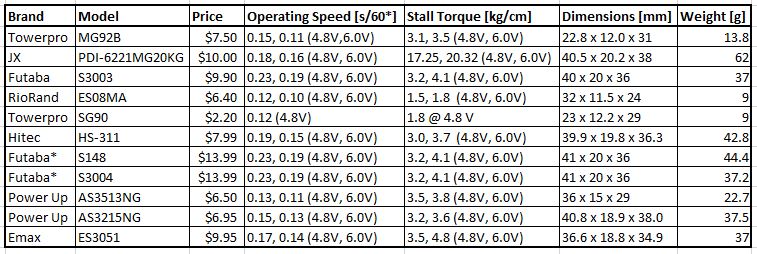
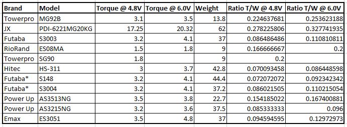
As the mission objective states that the Velociraptor will be a biped robot so the research from last semester’s MicroBiped using the servos as motors to perform walking proved to be the best option. A study was conducted to compare the different servo options for the Velociraptor (servo trade-off study). Last semester’s MicroBiped failed to successfully walk; therefore, to improve on this feature for the Velociraptor, 8-10 servos are to be used to provide enough torque to conform to The Level 1 Project Requirements. Complying with The Level 1 Program Requirement #2 and taking into account the cost-effectiveness aspect, the trade-off study will be conducted to determine which servo to buy that will keep the cost of the servos within the program’s budget of $400 dollars.
Size
To follow the Level 1 Project Requirements, the Velociraptor will be a toy robot of no more than the size of last semester’s MicroBiped and Titrus-III, roughly measured, 40cm x 13cm x 11cm.
Sensors
To comply with the Level 1 requirement #8, Ultrasonic sensors will be implemented for obstacle detection and avoidance as described in the mission. To control the balance of the Velociraptor when walking up inclines, another sensor will be implemented to determine position and orientation. A research of last semester’s choice of a gyroscope for its MicroBiped followed and a trade-off study (Link to Accelerometer vs. Gyroscope trade-off study) of the Accelerometer vs. Gyroscope, the accelerometer qualified as the better option for the Velociraptor to measure and relay orientation information of the Velociraptor. The system will collect real time data from the sensors and send them to a third party application, the Arxterra app, which will be controlled by the user.
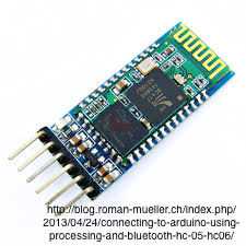
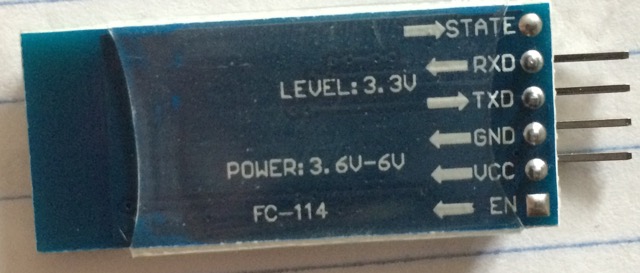
Communication
To control the Velociraptor wirelessly, an Android phone paired with the Arxterra Application will receive sensor data via a Bluetooth device and allow for remote control. Arxterra is a telerobotics company developing open source robots that can control the robots from anywhere with cell phone coverage. The Arxterra Control Panel allows for easy integration of a user interface on the Arxterra App to be controlled on the Android phone and thus fulfilling the Level 1 requirement #9.
Materials
The material of the Velociraptor must be strong and durable. A suitable material for this will be aluminum. Aluminum is both lightweight and sturdy and will be able to carry the added weight of the extra 2-4 servos that are to be implemented to the Velociraptor. Hollowing body parts on the CNC machine to manufacture a frame-like chassis will lower the weight while also reducing the costs of material. A study using SolidWorks will be conducted to verify the strength of aluminum to carry the weight of robot without bending or cracking.
Battery
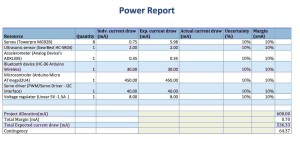
The battery for the Velociraptor will need to provide power for 8 servos and the microcomputer. It will need to be rechargeable and more cost efficient in the longer run. The battery should provide power for the Velociraptor to complete the mission in one trial and thus when decided what servos to use, the estimated time the robot will spend to complete the mission will be calculated. For the Velociraptor to statically walk, the battery should have a high discharge rate in order to deliver a large amount of power at one time for performing one step. For safety requirement, the maximum safe continuous discharge rate must be greater than the maximum current drawn from the servos and electronics board.
Electronic System Design
By: S&T Camilla Jensen, E&C Ashlee Chang

Elementary approach to mapping the system
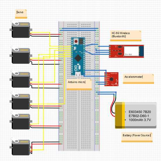
In order to accommodate all the requirements of the customer, the velociraptor will have many input sensors and output actuators in place. Based on the information obtained from the sensors, the velociraptor will in turn perform an action and output the information to the actuators. A list of all components is listed: sensors (ultrasonic sensor, accelerometer, Bluetooth), communication (Bluetooth in an Android), microcontroller, power source (battery), and actuators (servos). Below maps out a more complex block diagram. More details about the pin locations are shown in the Fritzing diagram.

Interface Definitions:

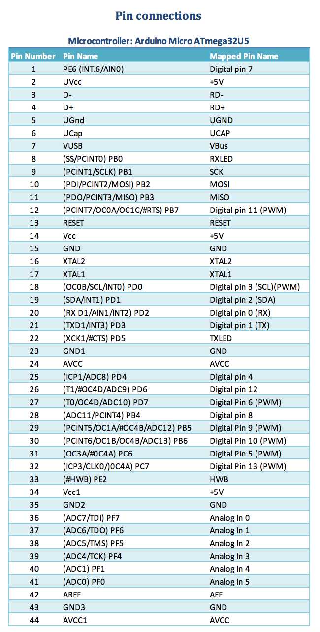
Table 1: Pin connections for Arduino Microcontroller
Table 1 shows the total number of ports on the ATmeg32U4 board in combination with the Arduino pins. To estimate the pins needed to connect the components to control the Velociraptor a comparison with table 2 has been made to eliminate the leftover pins.

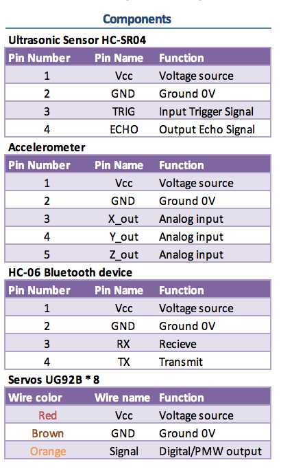
Table 2: Pin connections for components of Velociraptor
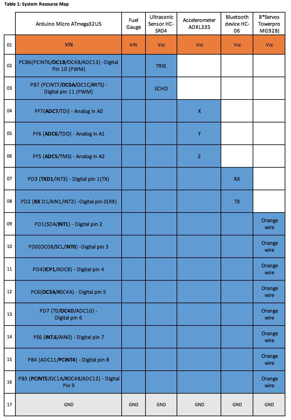
System Resource Map:
By: Camilla Jensen (Systems Engineer)

Table 1 shows the outcome of the comparison of table 1 and table 2 from the Interface Matrix. E&C engineer Ashley Chang performed a test of the of servo communication with the microcontroller and the test proved that the need for a servo driver as last semester used to communicate with the servos for the PMW signal is unnecessary as the servos are compatible to communicate with the microcontroller through digital I/O pins as well. Therefore, the servos for this semester Velociraptor are connected to the digital output pins 2-9 as shown in Table 1.
Fritzing Diagram:
By: M&D Mingyu Seo

Mechanical Design
By: M&D Mingyu Seo
Introduction
For the velociraptor biped, the design must not only be able to provide a new solution to incorporate biped features but also possible use for a future toy design. This design will demonstrate the feasibility of the dinosaur biped as a toy product and allow future semesters the flexibility of upgrading and reworking the design to be more interactive between the user and the robot. The design of the velociraptor biped will be based on structures designed by Titrus-III, created by Tokyo Institute of Technology, while incorporating new features such as ultrasonic sensor and accelerometer sensor.
Preliminary Sketches
Using the Titrus-III model as a reference, Figure 1 shows the drawing if preliminary sketches by roughly defining the size of each component, which will adhere to the Velociraptor standards as prescribed in our level 1 project requirements. One of the parts I’ve emphasized was to keep the base of the foot to be parallel to the body to ensure stability.
 Figure 1
Figure 2. shows the components that make up for the joint. The joint is made up of 8 different components, which includes a frame for the knee, 2 connectors from knee to ankle, 2 connectors for the 2 servos we’ll be using each leg, and 1 connector from knee to the body of the velociraptor to keep the legs stable and parallel to the body when we perform static and dynamic walking.

Figure 2
Design and Unique Task Descriptions
By: E&C Ashlee Chang, M&D Mingyu Seo
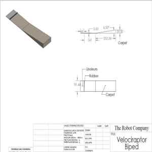
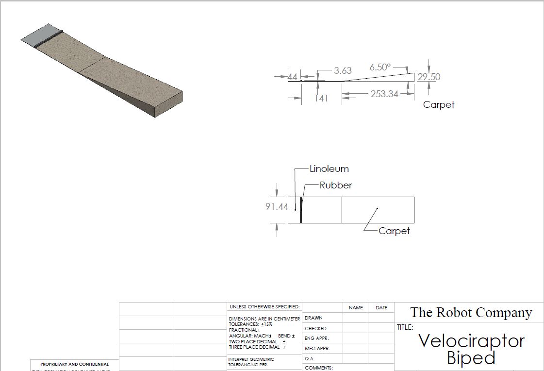
Subsystem description: Material and shape of the foot
Associated task description: Walking on two different terrains–linoleum and carpet.
- The velociraptor must have a foot shape that will not hinder its ability to walk. The soles on the velociraptor will be of a different material than that of the wood, metal, or plastic of the body. To handle both the slippery tiles and fuzzy carpet, the soles must have a friction coefficient large enough to adhere to the floor without falling. Materials such as sandpaper and rubber will be researched and tested. This subsystem is connected to level one requirement #8–traveling on two different surfaces.
Subsystem description: Leg joint mechanism
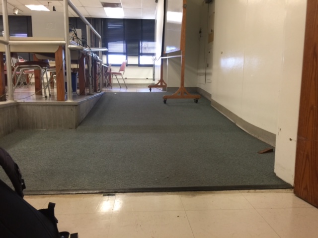
Associated task description: Walking over a 0.5 cm rubber divider
- Project level 1 requirements #6-8 describe the velociraptor being able to walk on two different surfaces. The mission room of VEC-501 has a rubber divider in between the hallway and the classroom of the ECS building, connecting the linoleum and carpet. The velociraptor must lift its foot high enough (over 0.5 cm) to be able to walk over this part of the mission. How tall the limbs are will determine how high the legs will be able to lift.
Subsystem description: Ultrasonic sensor
Associated task description: Object detection
- Project level 2 requirement #8 specifies the need for the velociraptor to detect objects. After walking over the rubber divider onto the carpet, the an object will be awaiting the velociraptor on the other side. This object will most likely be a wall, such as a notebook held up. The ultrasonic sensor will constantly update the distance between the velociraptor body and the object. Upon reaching a certain distance difference, the velociraptor must respond.
Subsystem description: Turning mechanism
Associated task description: Velociraptor must turn in the case of an object being in its path
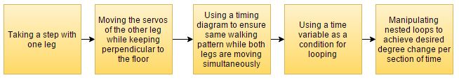
- Upon object detection using an ultrasonic sensor, the velociraptor must be able to turn to maneuver around this object. There is a minimum requirement of 90* capability to turn, as specified in level 1 requirement #11. The turning mechanism will either be implemented by: (1) one leg taking larger steps than the other, or (2) an extra servo for each leg positioned perpendicular to the other leg servos to spin the entire joint. Level 2 requirement #9 specifies the need for the extra servos to successfully turn.
Subsystem description: Bluetooth
Associated task description: The velociraptor must be controlled wirelessly
- Level 2 requirement #11 describes the velociraptor communication being wireless. The velociraptor will pick up a signal from the user using a Bluetooth module connected to the Arduino board.
Subsystem description: Android Arxterra App
Associated task description: A phone app will be used to remotely control the velociraptor
- Level 2 requirement #10 shows the method of control of the velociraptor will be using an Android phone running the Arxterra App. The Bluetooth signals of both the phone and the velociraptor will be transmitted to one another; this includes sensor information and actions to perform.
Subsystem description: Balancing
Associated task description: Use of servos to move the head and tail to balance while walking
- Project level 1 requirements #6-7 describes the velociraptor being able to stand on 2 legs and be able to statically walk, which uses the head and the tail as counterweight to balance on one leg while the other leg is up. Dynamic walking will require the velociraptor to walk without the head and tail for balance. Upon reaching the incline, the accelerometer sensor will detect disorientation and prevent the velociraptor from falling backwards by sending real-time data for the user to orientate the position of the servos. Simulations will be done through SolidWorks to determine the center of mass.
Subsystem description: Servo speed
Associated task description: Dynamic walking
- Because the velociraptor must be able to perform dynamic walking (level 1 requirement #7), the servo speed becomes an important factor in the trade-off studies. Operating speed is measured by how many seconds it takes for a servo to rotate 60*. Both the legs (for walking) and the head and tail (for balancing) must be able to rotate at this quicker rate, so ideally all servos will be of the same operating speed and have the capability of spinning quickly. The quickest ones in the trade-off studies at 4.8 V of power were 0.12 s/60* and the slowest ones were 0.23 s/60*.
Subsystem description: Safety
Associated task description: Product category is a toy and must be safe for certain age groups
- The objective states the velociraptor will be manufactured as a toy, and must also satisfy level 1 requirement #3–CSULB’s health and safety policy. The velociraptor shall not be of a hazard to the user, examples including sharp edges, ways to be electrocuted or burned, etc.


