Fall 2016 Velociraptor (W): Software Block Diagram

By Gifty Sackey (Mission, Systems, and Test)

Approved by:

– Lam Nguyen (Project Manager)

– James Lee (Division Manager for Mission, System, and Test)

Table of Contents

Introduction

The purpose of this blog post is to discuss and summarize the control functions that will be required in the programming of the robot. It will cover the software block diagram and introduce the set of tasks that the software had to accomplish. For the mission profile for the Velociraptor shall participate in the Game Arena and statically walk. The software flow chart that is attached, allows users to see how the Arxterra firmware will be modified and the programmed through the 3DoT board.

Software Block Diagram – (Old)

software-block-diagram-old

Diagram 1. Software Block Diagram

Software Block Diagram – (Updated)

software-block

Diagram 2. Software Block Diagram Updated

In the event that a command is sent via Bluetooth from the ArxRobot App, the command decoder and handler functions will be executed on the action. The software block diagram, allows readers to gain an insight on the inputs that the robot functions will be taking as well as the outputs. For this blog post, I will be explaining in detail how the velociraptor will perform when the right motor is the only thing allowed to move. When the velociraptor is being moved and controlled by a single motor, the velociraptor is making a turn. In the case of the right motor moving, this indicates that the velociraptor is turning left. A turning left subroutine code would then be initiated as well as servo commands. In order for the velociraptor to be able to make a complete turn, it would have to shift its center of gravity over the left leg by moving the servo 30 degrees from the neutral position so that the it is balanced over that specified foot.

For the velociraptor to achieve static walking, the control codes will be designed such that both motors will be moving out of sync. While both motors are moving out of sync, as engineers, we need to make sure that the revolutions per minute (rpm) should have different values for both motors while having both legs be 180 degrees apart. The servo would then be moved over the left leg but then both motors would be required to move 180 degrees at the same rpm value and then stop in order to complete a step. At this point, the velociraptor needs to maintain balance so it needs to shift the servos at a 60 degree angle in order to ensure the center of gravity is on the right leg. At this point, the robot must move both motors 180 degrees forward to complete a step. The robot would then repeat this process until a different command is called from the Arxterra application.

Fall 2016 Velociraptor (W): Validation and Verification Test Plan

By:

– Lam Nguyen (Project Manager – Velociraptor Wednesday)

– Paul Ahumada (Project Manager – Velociraptor Thursday)

– Gifty Sackey (Mission, System, and Test Engineer)


Introduction


The final validation and verification test plan was written to verify the requirements for the Velociraptor through the Validation and Verification Matrix.

Link: verification-and-validation-matrix

Verification & Validation Test Plan

Below are the validation and verification test plan that supports our level 1 and 2 requirements.

Link: verification-and-validation-test-plan-results

Fall 2016 Velociraptor (W): Center of Mass

By Aaron Choi (Manufacturing Engineer)

Approved by

-Lam Nguyen (Project Manager)

-Tim Haddadian (Division Manager for Manufacturing)

Table of Contents

Requirements

Level 2-10 The center of gravity on the axis of the head and tail shall be controlled by one servo while being placed over the foot

Introduction

The center of mass is crucial for the design of the Velociraptor. To fulfill the Level 2-10 requirement, the center of mass should be placed over the foot. To observe the center of mass, the SolidWorks model of the design is required.

Library of Density

To observe an accurate center of mass, the mass of each observed through SolidWorks. There is no direct way to edit an object’s center of mass. However, a material can change its mass through density. Figure [1] below shows the example of a custom density for a material. The mass was either given from datasheets or weighed through a weight scale. The GM9 [1] and SG90 [2] mass were given through their respective datasheet. The volume of each Solidworks file were observed through the Measure tool in Solidworks. Then the density was calculated with mass divided by volume. Then the units were converted to match kg/m^3. Certain materials contained their density, such as Birchwood [3].

figure-1

Figure [1]

Density of the 7.4 Li-Po battery.

table-1


Table[1]

The table shows the density used for each custom material in Solidworks.

Center of Mass of Velociraptor

From the custom library of densities, the accurate center of mass was found. Then moving the head and tail through Solidworks, the head and tail were shifted at an angle. The angle found was 35 degrees.

figure-2
Figure [2]

The black and white dote represents the center of mass.

Conclusion

In conclusion, the center of mass was observed over the foot at 35 degrees. This was calculated by subtracting 65 degrees, found through Solidworks, to 90 degrees. This meets the Level 2-10 requirement.


Reference

[1]  https://solarbotics.com/product/gm9/


[2]  http://www.micropik.com/PDF/SG90Servo.pdf


[3] http://www.engineeringtoolbox.com/wood-density-d_40.html


Fall 2016 Velociraptor (W): Control Algorithm Code #2

By: Taylor Farr (Electronics and Controls)

Approved by:

– Lam Nguyen (Project Manager)

– Ryan Daly (Division Manager for Electronics and Control)


Table of Contents

Summary


The code for CDR utilizes IR sensors as rotary encoders. This was an okay method because it allowed for us to move the DC motors exactly 180 degrees. This is method could be improved with rotary encoders. We chose to use rotary potentiometers that can move a full rotation. Our PCB is powered by 3.3 volts, which means that the potentiometer value will vary between 0 and 3.3 volts. This is an analog signal, and our PCB only communicates via I2C.

[Link to A/D converter test]

We used the Adafruit ADS1015 to accomplish this. The test plan revealed that a span of 0-3.3 volts equates to a span of 0-1100 bits. This test proved flaws which improved the previous code, and allows for more precision in controlling the DC motors. This way, turning right and left will be more accurate. The option to move the motors at an angle of 90 degrees will keep the motors in place while the other leg moves continuously.


Code Description


The intent of the code is simple. Both legs will start off 180 degrees out of phase with the left leg forward and right leg in the back. The servo will move the head and tail to the left. The motors will both move 180 degrees to complete a step then stop. The head and tail will shift over the right leg. The motors will move 180 degrees again, then stop. The head and tail will shift to the left again. This completes the move forward subroutine.

Since the old encoders only move 180 degrees, turning would be impossible. The reason is that the legs cannot be moved to a position where all the center of mass can be placed on one leg without falling over. With the precision of the rotary encoder sensor, I can move the leg so that it is standing straight up. Once this movement is accomplished, the other leg will run continuously to turn. A similar process is used for turning the opposite direction.


Conclusion


Utilizing the rotary encoders and the I2C A/D converter allows for motors to be easily controlled. We can now position them with greater accuracy than the optical encoders. Figures 1 and 2 show the code used with comments.

23

Figure 1: First part of the control algorithm

24

Figure 2: Second part of the control algorithm


Resources


Fall 2016 Velociraptor (W): Hardware Design


By Aaron Choi (Manufacturing Engineer)

Approved by

-Lam Nguyen (Project Manager)

-Tim Haddadian (Division Manager for Manufacturing )


Table of Contents

Requirements

Level 1-2 requirement states that the Velociraptor budget shall not cost more than $102.

Level 2-1 The center of gravity on axis of legs shall be controlled by one servo. The head and tail shall not exceed [data to be calculated] degrees in order to avoid the robot from tipping over.

Level 2-3 The Velociraptor shall have two legs mechanism [Theo Jansen or UCI] in standing position to support the mass of robot with 50% margin.

Level 2-4 The Velociraptor should control the center of gravity on the axis of the H/T should be controlled by one servo.

Level 2-7 The Velociraptor shall have a foot design that uses [springs or struts] to maintain foot angle at minimum 6.5 degrees when not in contact with ground.


Introduction

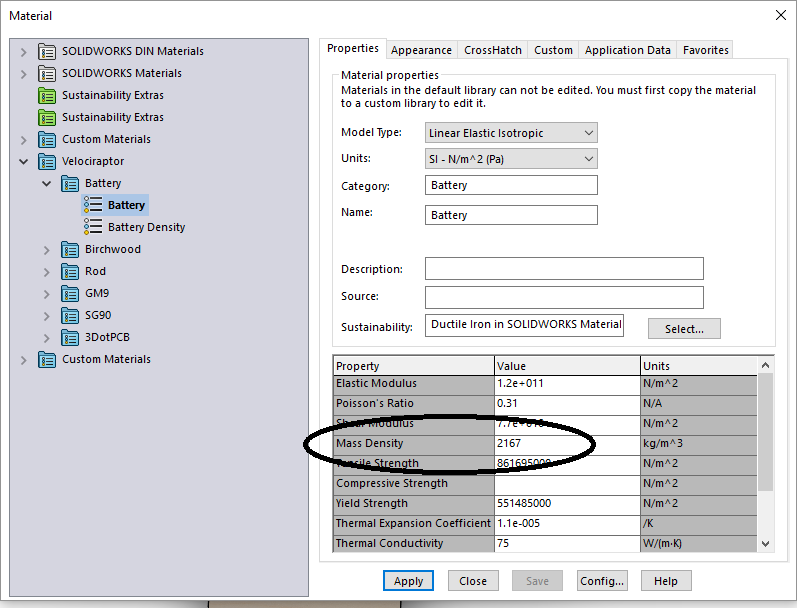
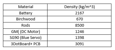
For the Wednesday Velociraptor, the  Theo Jansen leg mechanism shall be implemented to meet the Level 2-3 requirement.  For the materials utilized, Birchwood is chosen to fulfill the Level 1-2 requirement and based off trade-off studies- [1].

Design

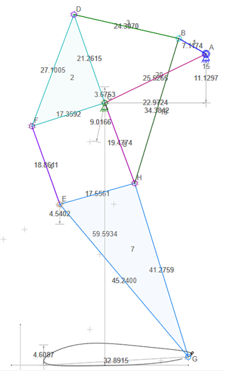
For the design, a simple CAD program called Linkage was used to model the walking path of the design. The CAD program, created by David Rector, allows users to design two dimensional mechanisms and simulate the movement of those mechanisms [2]. From this CAD program, the Jensen leg mechanism were used to model and observe the walking path. Linkage allowed users to adjust the lengths of each linkage. From experimenting the lengths, the finalized leg design for the Velociraptor was chosen. This design was chosen to increase the vertical height of the legs while maintaining the walking motion.
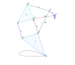
figure-1

Figure [1]

The figure above shows the Theo Jensen leg mechanism.
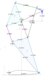
figure-2

Figure [2]

The figure above shows the design used for the Wednesday Velociraptor.


PDR Demonstration

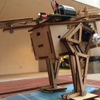
Figure [3] shows the design that was presented for the Preliminary Design Review demonstration. This design did not contain a head and tail, however the Theo Jansen leg mechanism was implemented.
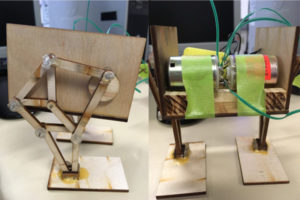
figure-3

Figure [3]

The design presented for PDR.


Some issues occurred during demonstration. The DC motors used did not provide enough torque for the Velociraptor to walk. The shaft of the DC motor constantly slipped in the shaft of the rotation piece of the Velociraptor. The linkages were not stable enough. To fix the unstable linkages, another linkage parallel will be added.


CDR Demonstration

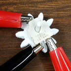
Figure [4] shows the design that was presented during the Critical Design Review presentation. The outer shell, foot design with toe joint, and head and tail were included into this design. The DC motors used were the GM9, which were chosen from trade-off studies from Taylor Farr. The HS-322HD servo was used to control the head and tail. The servo installed was to fulfill the Level 2-1 requirement. An outer shell was implemented for a see-saw design for the Velociraptor to shift the mass forward when walking on incline. This would balance the robot when walking on incline surfaces. To control the platform, a servo will be implemented which meets the Level 2-3 requirement. The passive toe joint was used based off research [3] and to meet the Level 2-7 requirement. The ankle of the foot was positioned at the tip of the triangle for the leg. This helped match the walking motion of the Velociraptor. The additional linkages were able to stabilize the links unlike the PDR model. This improved the balance of the robot with stable legs.
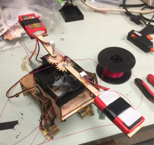
figure-4

Figure [4]

The body design presented for CDR.
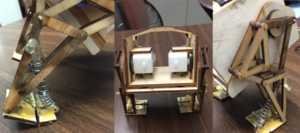
figure-5

Figure [5]

The leg and foot design presented for CDR

The model failed to walk without falling backward or forward. The head and tail were unable to move due coding. A solution given by Professor Hill was to move the GM9 motors on the outside. This was to ensure that the center of mass would be directly over the foot for the Velociraptor.

CDR Demonstration 2.0

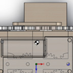
Figure [6] shows the design that was presented for the Post CDR demonstration The GM9 motors were moved to the outside to shift the center of mass easier. The feet length of the robot were also increased to increase the surface area of contact. An issue with the previous design was that as the robot walks, the ankle at which it walks did not match the walking motion of the robot. Rather than using the HS-322HD servo, the SG90 servo was installed.
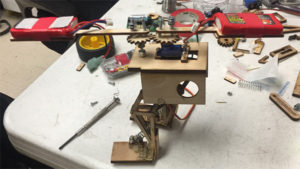
figure-6

Figure [6]

The body design presented for Post CDR demonstration.


When presenting the design, the robot could not walk forward without balancing by itself. One addition that would be able to solve this issue is add traction material to the bottom of the foot. The spring of the toe joint was unable to support the mass of the robot, causing the robot to fall when balancing. To resolve this, further experimenting with springs will be carried out.


Game Arena Design

Due to time constraints, Paul Ahumada’s physical model was implemented for the Game Arena and test plans. For this design, a body was used that could utilize both Ahumada’s design, and the Velociraptor leg design. Ahumada’s design revolved around using gear trains to rotate the leg.
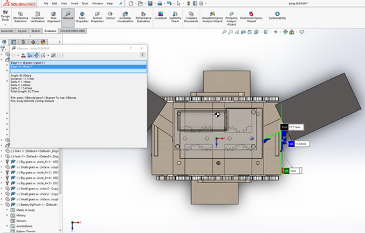
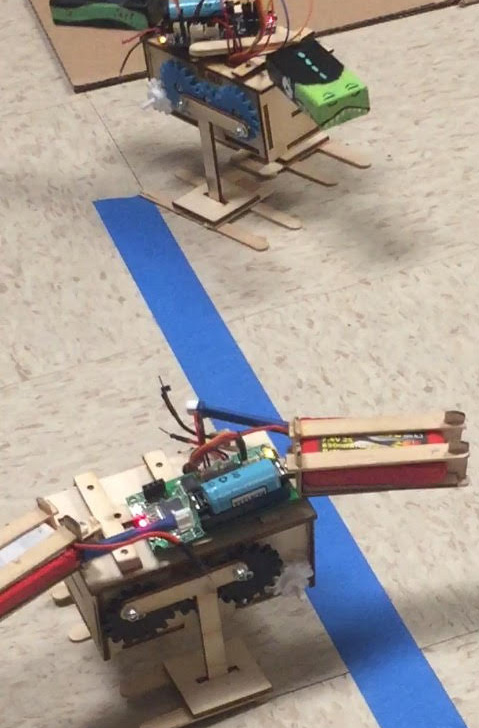
figure-7

Figure [7]

The top robot is the Thursday Velociraptor. The bottom robot is the Wednesday Velociraptor.


Post Game Arena Design

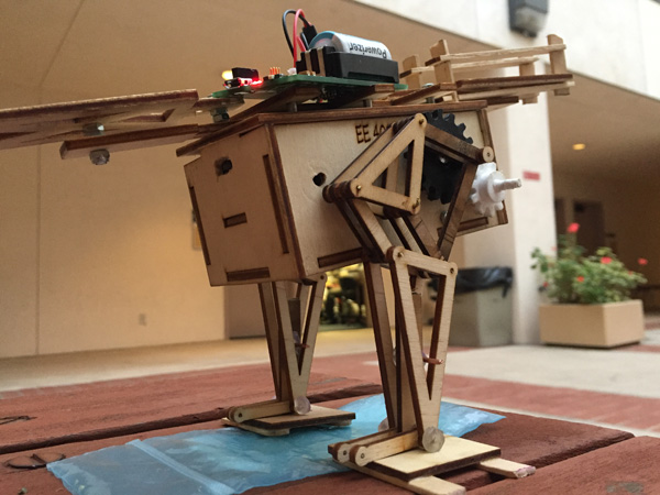
Figure [8] below shows the design shown to the customer after the Game Arena and Validation plan was finished. The Jansen linkage installed onto the body of Ahumada’s design [4]. Although the Velociraptor could not statically walk without tipping over, the walking motion did show that the robot could move forward.
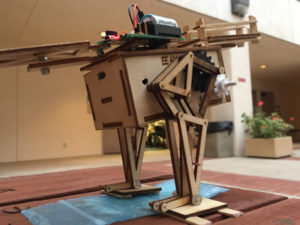
figure-8

Figure [8]

The design with the modified Theo Jansen linkage.


Conclusion

The hardware prototypes implemented subsystem designs which derived from the level 1 and level 2 requirements. The issues that were faced were due to center of mass. The Velociraptor could not balance well due to the center of mass. Additionally, the body would continuously sway. A possible solution would adding an additional linkage that attaches from the body to the rotation shaft of the motor that would help stabilize the robot.


References:

[1]http://arxterra.com/material-trade-off-study/

[2] http://blog.rectorsquid.com/linkage-mechanism-designer-and-simulator/


[3]http://ocean.kisti.re.kr/downfile/volume/icase/JOJDCV/2011/v17n7/JOJDCV_2011_v17n7_659.pdf

[4] http://arxterra.com/mechanical-design/

Fall 2016 Velociraptor (W): System Block Diagram

By: Gifty Sackey (Mission, System and Test Engineer)

Approved by:

– Lam Nguyen (Project Manager)

– James Lee (Division Manager for Mission, System and Test)


Table of Contents

Introduction


The system block diagram describes how all the signals connect to all the components and communicate with the 3DoT board. Aside from the 3DoT board, which was provided by Professor Hill, there is an external PCB which is designed by the electronics and controls engineer and fabricated by the manufacturing engineer. On the Velociraptor our shield will have a stepper motor drivers (A3901) for 2 stepper motors. These two devices are the linear actuators that will change the pattern of the step. For instance if the Velociraptor needs to go up an incline, it would be able to step higher and not hit its foot against the bottom of the incline. In order to have the stepper motor driver be compatible with the I2C interface, we will utilize a GPIO expander that is I2C compatible. The driver will control the linear actuators. The linear actuators will change the radius of the rotational movement which will change the motion of the leg movement.

Design 1

3dotboard

Diagram 1: First design for System Block Diagram

Design 2

In our final design of the System Block Diagram we had added a color scheme to the one below. Following from the external battery on the shield (external PCB layout) the colored lines indicates the voltage level before going stepping down in voltage for certain regions of the schematic. The orange lines indicate the 7.4V battery going through the LM7805 LDO. The blue line is connected to the 3DoT board which powers the 2 DC motors and the servos. The blue line also steps down again though the LDO on the 3Dot board dropping down to 3.3 V. This in part will power all of the sensors on the external PCB board.

2

Diagram 2: Finalized System Block Diagram

External Power Supply

The Velociraptor is required to participate in the end of semester game alongside with other robots. The Velociraptor will be designed to last a duration of the game which is 1 hour. Two external batteries will be used in addition to the battery power provided through the 3DoT board. The external battery of choice is the YPG 850mAh 7.4V 25C 2S Li-Po Battery which will be stepped down by the LM7805 LDO to 5V at 1.5 amps maximum. The output of the LDO is connected to the external battery connection on the 3DoT board.

Balance – IMU

Above the stepper motor connections are the legs of the Velociraptor (Figure 1). The orientation movement of the robot will be sensed by the IMU. The IMU is connected to the PCB via I2C interface and its purpose is to measure the angles and acceleration in x, y and z directions. By incorporating the IMU in our design, we are able to determine if the velociraptor is unbalanced. The control algorithm that will be implemented for the velociraptor will be a closed loop algorithm which is always checking against a calculated value that corresponds to the velociraptor’s balance.

Position Tracking – Rotary Sensor

The connections of the DC motors controlling the legs need to be connected to the rotary encoders. Since the rotary encoders are not I2C compatible, they require a connection to an A/D converter. In the case of the velociraptor, a 12-Bit ADC converter type of ADS1015 has been chosen.

Bluetooth Commands/Telemetry

The Arxterra Control Panel is made up of the controls that our software and firmware will be using to control the velociraptor. The velociraptor robot will be able to receive commands through two main modes, community mode(laptop) or remote control mode(phone). In the event that the velociraptor will be receiving commands from the android phone, the Arxterra app would need to be configured into a remote control mode to control the robot. The 3Dot board is embedded with an HM-10 Bluetooth module which aids the communication of the software to the robot. A software block diagram for the velociraptor can be viewed to gain a better understanding of the software controls for the velociraptor. This Bluetooth module is compatible with either an Android or Apple iPhone. Users are required to have a membership account with the Arxterra company in order to achieve this communication platform necessary to have the robot receive commands. For the velociraptor group, the goal is to modify the existing move command code in the 3DoT library and in turn have the velociraptor be able to turn left, turn right, walk up and down inclines and lastly statically walk.

Embedded in the 3DoT board is a TB6612FNG motor driver which will be needed to drive two GM9 motors that will be used to control the legs. Each motor will be attached to each leg mechanism of the robot. The motor driver’s purpose is to receive low current control signals from the 3DoT board and output a higher current signals. These signals can drive the motors that move the legs.

Conclusion

In the end the first thing we needed to consider was how much torque we needed to move our robot. Once we had the mass figured out we could determine the amount of current needed to power the robot. After that we account for all of the actuators, sensors, and other electronic devices so that our robot is fully functional. If our design changes then

Resources

[1] http://web.csulb.edu/~hill/ee400d/Technical%20Training%20Series/04%20Robot%20Block%20Diagram.pdf

Fall 2016 Velociraptor (W): Custom Telemetry Commands

telemetry-pic3 By: Gifty Sackey (Mission, System, and Test Engineer)

Approved by:

– Lam Nguyen (Project Manager)

– James Lee (Division Manager for Mission, System, and Test)

Table of Contents

Introduction

Inaddition to the custom command for static walking that was created for the Velociraptor (W) group, we also created four additional custom telemetry commands. For the telemetry we will be displaying the roll, pitch and the left right rotary sensor values. A rotary encoder will be able to tell us how much in each direction the encoder has been turned. The custom command is when we have information that is being sent to the robot from the user. The custom command that we created for static walking for instance; it lets the Velociraptor know when to start walking. However, telemetry would be the robot sending back information to the user what the leg placement is.

Telemetry Commands

Similar to the custom commands being set up on the Arxterra App, the telemetry commands are also set up in the application. Both the custom commands and telemetry are set up in the developer mode which can be accessed on the main menu. Once the Arxterra app is open and the developer mode has been started, click on the gear icon that is right below the camera image. Select custom command and telemetry configuration from the drop down menu that pops up. By clicking on the “+” sign that pops up,  the user is able to create the telemetry commands for the roll, pitch, rotary left and rotary right commands.

telemetry-pic1

Diagram 1: Developer mode with gear icon

telemetry-pic2

Diagram 2: Possible Option List : Select Custom Command & Telemetry Configuration

 Key Commands

For each of the commands created, the user would need to assign a specific hexadecimal value to it. For the roll, pitch, rotary_r and rotary_l commands, the hexadecimal values that were assigned were 0x41, 0x42, 0x43 and 0x44 respectively. A figure of the assignments can also be found below this section of the blog.
telemetry-pic3

Diagram 3: Telemetry command hexadecimal assignments

Once the custom telemetry commands have been created in the Arxterra app, there are a few additional lines of code that would need to be included in the Arduino code in order to be able to receive values. In the Arduino code, the user would also need to define the variable names with their respective hexadecimal values. A Packet ID would also need to be created to in order for the program to know that it is the start of a telemetry command.

telemetry-pic4

Diagram 4: Arduino assignment of custom telemetry commands

telemetry-pic5

Diagram 5: Packet ID created for each telemetry command

Testing

For the figure 6 below, hard coded values of roll =35, pitch = 10, rotaryLeft = 23 and rotaryRight = 46 were created in order to test the telemetry commands and determine if any values were received on the control panel. Unfortunately for the Wednesday velociraptor group, the electronics engineer was unable to include his actual coding commands for the sensors with the telemetry code. As a result, the only way the Wednesday velociraptor group was able to test the telemetry code was through hard coded values and not by actually receiving the senor values.

telemetry-pic5 telemetry-pic6

Diagram 6: Telemetry code testing

For figure 7, viewers are able to see the hard coded telemetry values of roll =35, pitch = 10, rotaryLeft = 23 and rotaryRight = 46 being displayed on the control panel.

telemetry-pic7

Diagram 7: Arxterra Control Panel displaying the telemetry output

Resources

  • None

Fall 2016 Velociraptor (W): Fritzing Diagram

By: Taylor Farr (Electronics and Controls)

Approved By:

– Lam Nguyen (Project Manager)

– Ryan Daly (Division Manager for Electronics & Controls)

Table of Contents

Requirements

  • The velociraptor shall utilize a printable circuit board (PCB).
  • The velociraptor shall use a 3DoT board library and utilize I2C to communicate with sensors, A/D converter, and GPIO.

Introduction

In order to design a PCB that will be placed on top of the 3DotBoard, several drafts will be used before we find our final design. The Fritzing software will be used to design the PCB. It will also help us see where the necessary connections to be mad will be. This will help our systems engineer route the cable tree.

fritzingimage

Diagram 1: Fritzing Diagram

In the center of Diagram 1 is a model of the 3dot board modeled by Alan Valles (biped E&C Wednesday). The 3dot board has an internal battery connection, an external battery connection, two servo headers, two motor connectors, and a female connector for the external PCB. For our initial design, we have two external batteries to be used for power and as weights for the head and tail. It is also seen that there will be two servos. One servo is to control the movement of the head and tail. The other servo was to be used to control the linear actuators which would change the linkage that controls the leg movement. 2 dc motors are seen to be used to drive the legs. For the I2C connection, everything here will be on the PCB. The I2C pins have 4 pins. One for power, one for ground, one for serial clock, and the last one for serial data. On the data sheet for each device, we can find where all the matching connections are. The red device is the IMU that we will use. It essentially requires to be connected to Vcc, ground, serial clock, and serial data. This is the same case for the A/D converter which is the blue device on the bottom right corner of the figure. Connected to the A/D converter is the two rotary encoders.  These require to be connected to power and ground. The signal from those are connected to the inputs of the A/D converter. The final unit on our PCB is the GPIO port. The GPIO port is I2C compatible, and it is used to connect to the stepper motors. They will act as outputs that will drive tiny stepper motors.

Conclusion

Now that the Fritzing design is complete, we have a better understanding of what our PCB design will be like as well as the wiring of the system. All of the components that will be on the PCB are I2C compatible, so there is no problem.

Resources

[1] http://web.csulb.edu/~hill/ee400d/Technical%20Training%20Series/07%20FritzingDocumentation.pdf

Fall 2016 Velociraptor: EagleCAD schematic

By Taylor Farr (Electronics and Control)

Approved By:

– Lam Nguyen (Project Manager)

– Ryan Daly (Division Manager for Electronics and Control)

Table of Contents

Requirements

L1 – 9: The velociraptor shall utilize a printable circuit board (PCB).

L1 – 10: The velociraptor shall use a 3DoT board library and utilize I2C to communicate with sensors, A/D converter, and GPIO.

Introduction

After the Fritzing design is complete an EagleCAD schematic has to be designed to create a PCB and move the project forward. EagleCAD is a software program that allows the user to place components on the board, and wire all the connections properly. Pins such as I2C pins can be connected across the network.

eaglepicture

Figure 1: Eagle Schematic

Here, all of the components are seen with all of the connections visualized. In the top corner is the 3dot board. The external battery connection is connected to the output of the LDO (more on this later). The two servos and two motors are connected to the 3dot board. On the top right is the analog to digital converter. It is wired correctly according to the datasheet. It allows for four inputs. Two inputs will be used for each rotary encoder. On the middle left contains all of the connections. The female connectors for the IMU are on the left. To the right of that is the connections for the rotary encoders. The connections for the stepper motors are on the right. These connections connect to the stepper motor driver that is on the right. The stepper motor driver is connected to the GPIO expander located in the middle on the bottom. On the bottom left, the LDO is found. The external batteries that will be on the head and tail are going to be inputs to the LDO. The LDO regulates the output down to 5 volts and 1.5 amps. The connects to the external battery connector on the 3dot board in order to drive the servos at 5 volts. To the right of the LDO are some light emitting diodes to show that the PCB is working.

Conclusion

The completed fritzing diagram and the Eagle schematic pushed our final design closer to the  completed product. We now have a concrete version of our schematic. This is then sent to the manufacturing engineer to order the external PCB layout.

Resources

[1] http://web.csulb.edu/~hill/ee400d/Technical%20Training%20Series/10%20Schematic%20Capture%20with%20Eagle%20CAD.pdf

[2] http://arxterra.com/fall-2016-velociraptor-w-fritzing-diagram/

Fall 2016 Velociraptor (W): Mass and Power Report

By Gifty Sackey (Mission, System, Test Engineer)

Approved by: Lam Nguyen (Project Manager)

Table of Contents

Mass Report

The mass of the Wednesday Velociraptor was 348 grams. As part of the level two requirements, the mass of the robot should not be greater than 350 grams. The mass of the robot was an important thing to consider because the DC motors needed to be able to drive the mass allotted.

In calculating the mass of the robot, a motor torque test was performed in order to make sure that we were aware of any constraints. The Wednesday Velociraptor is controlled with two GM 9 motors which based on the torque test can drive up to 1000g.  With our Velociraptor having an overall weight of 348 grams, we were confident that the DC motors would be able to drive the mass.

Power Report

This table down below is a representation of the power report schedule that was created by the Velociraptor senior design group. For the mass report, there were a series of tests that were performed in order to test whether the Velociraptor would be supplied with enough power to move it. This duration request was necessary to satisfy the requirement which stated that: “The 3rd generation Velociraptor shall operate for a minimum of one hour with an external power source minimum of 1560 mA-hours.

In order to successfully pass this requirement, the measured current drawn from the Velociraptor needed to be based on the components needed to accomplish our goal. First thing was to determined the stall current from each component and narrow down a type of battery our robot needed. After the battery was determined we needed to find an operational current rating from our components which were the 2 DC motors, one servo, and two stepper motors.

Change in design

Our project objective changed by gearing the projects direction to static walking as opposed to dynamic walking. As a result we took out components out from our design such as the two stepper motor driver. With our new design a test was performed in order to fulfill this requirement and was successfully passed. An in depth procedure of the testing performed can be found in the test validation and verification test plans.

Test Plan link: