By: Elizabeth Nguyen (Project Manager), Melwin Pakpahan (Missions, Systems, and Test Engineer), Yasin Khalil (Electronics & Control Engineer), Zachary de Bruyn (Electronics & Control Engineer), Railan Oviedo (Design & Manufacturing Engineering)
Preliminary Design Document
Program Objective & Mission Profile
Written by Elizabeth Nguyen
Program Objective
The 3DoT Chassis (the name is expected to be changed) is expected to be 3D-printed as a single assembly, based on the Paperbot. It will be a toy robot with a paper shell that will resemble the mascot of CalState Long Beach (CSULB) Prospector Pete. The robot will be controlled through the arxobot app/control panel. The DC motors (GM6) and the planetary gear system will remain the same as used for Paperbot.
Mission Profile
The 3DoT Chassis will be able to (1) remotely navigate a maze while recording its path (that is determined on the day of demonstration) with its sensor shield and (2) autonomously navigate the same recorded maze path while other autonomous toy robots are present.
Source: Project and Mission Objectives
Requirements
Level One Requirements
Written by Elizabeth Nguyen
Program Requirements
- The 3DoT Chassis shall be completed by Wednesday, December 13, 2017.
- This requirement coincides with the last day of class and this is the projected demonstration date for all toy robots.
- The 3DoT Chassis shall cost no more than $200 as projected by the customer.
- The 3DoT Chassis will be a toy robot.
- This requirement is defined through the customer expectations.
Project Requirements
- The 3DoT Chassis shall use a 3DoT Board (based on Project and Mission Objectives).
- The 3DoT Chassis shall navigate through a maze with remote control through the ArxRobot App or the Arxterra Control Panel (based on Project and Mission Objectives).
- The 3DoT Chassis shall be no larger than 4 x 3.5 x 3 inches.
- These measurements were taken at the widest dimensions of the chassis since it tapers at the bottom.
- The 3DoT Chassis shall be able to memorize a path through the maze that is taught by the user (based on Project and Mission Objectives).
- The 3DoT Chassis shall be able to autonomously travel down the path that was memorized (based on Project and Mission Objectives).
- The 3DoT Chassis should be able to navigate the maze and avoid collisions when multiple robots are in the maze.
- This requirement is not completely defined because the project managers need to determine a way for the robots to avoid each other during their demos.
- The 3DoT Chassis shall have a chassis that is 3D printed.
- This is derived from a customer expectation.
- The total 3D print time of 3DoT Chassis’ parts shall not exceed 6 hours (based on Project and Mission Objectives).
- The main body of the body shall be of one solid piece.
- The 3DoT Chassis shall be easy to assemble.
- The 3DoT Chassis Paper Shell shall resemble the CSULB mascot, Prospector Pete.
- This is a customer expectation.
Level Two Requirements
Written by Melwin Pakpahan
System Requirements
- The 3DoT Chassis shall operate for no less than 20 minutes.
- The 3DoT Chassis shall have a maximum speed of 19.5 centimeters per second.
- The 3DoT Chassis shall have a custom PCB to accommodate for its sensors.
Subsystem Requirements
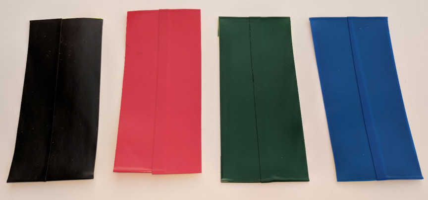
- The 3DoT Chassis shall be powered by a RCR123A Lithium Polymer battery.
- The 3DoT Chassis shall use a planetary gear system for mobility.
- The 3DoT Chassis shall have a sensor shield on the front.
- The 3DoT Chassis shall have a mechanism for counterweight attached to the shield.
- The 3DoT Chassis shall utilize two GM6 brushed DC motors.
- The 3DoT Chassis shall use a TCS34725 RGB color sensor to navigate the maze.
- The 3DoT Chassis shall use a TCS34725 RGB color sensor to detect and avoid other robots in the maze.
Design Innovation
Written by Elizabeth Nguyen
Caster Wheel
During the creativity exercise, our team determined that the caster wheel required a more innovative solution. There was a need to compensate for the uneven weight distribution caused by the smartphone resting in the front. Previous designs have used a simple castor wheel.
Based on the solutions developed from the suggested techniques (Duncker diagrams, different point of views, forced relationships, etc.), we decided not to implement them. Some were not feasible and there were other tasks that required more attention such as the custom PCB for the SAMB11 and the planetary gear system, which will be addressed.
Gear System
In continuation to the mentioned task that is considered urgent, the implementation planetary gear system is a customer expectation and a potential challenge for the team. It is aesthetically pleasing, which is why the gear system must specifically be planetary; however, this design did not work with a wooden chassis due to friction.
What has changed was allowing COTS gears since they cannot be 3D-printed concisely nor have a strong structure to work. Instead, the focus for the team is to determine an innovative design for the gear system while appearing planetary.
The challenge also discovered was for a true planetary gear system, torque comes from the middle gear, which then rotates the smaller planetary gears, allowing the wheel to turn. However, with the current chassis design, torque comes from the top gear, which will turn the rest of the gears.
Gear studies will be performed.
Custom PCB to replace 3DoT Board
A challenge provided for the team is to design and assemble a custom PCB that will replace the 3DoT Board that is used to power and control the robot. The ATMega32U4 will be replaced with the SAMB11 and there will be an implementation of the IFA on the SAMB11 Board as discussed below.
ATMega32U4 replaced with SAMB11
The current 3DoT Board v454 has components that are incorporated separately on the PCB as opposed to the SAMB11 where those components are built-in [1]. Benefits from replacing the chip would include less power for the SAMB11 because less components would be required ont he PCB and would not require the HM10 to be implemented onto the board because bluetooth is also integrated.
Implementation of IFA on SAMB11 board
Because of the replacement of the ATMetga32U4 with the SAMB11, an antenna is required for communication purposes between the users (our team) and the board itself. An Inverted-F Antenna was chosen and will communicate with the board using 2.4 GHz.
References:
[1] Design Guide of SAMB11
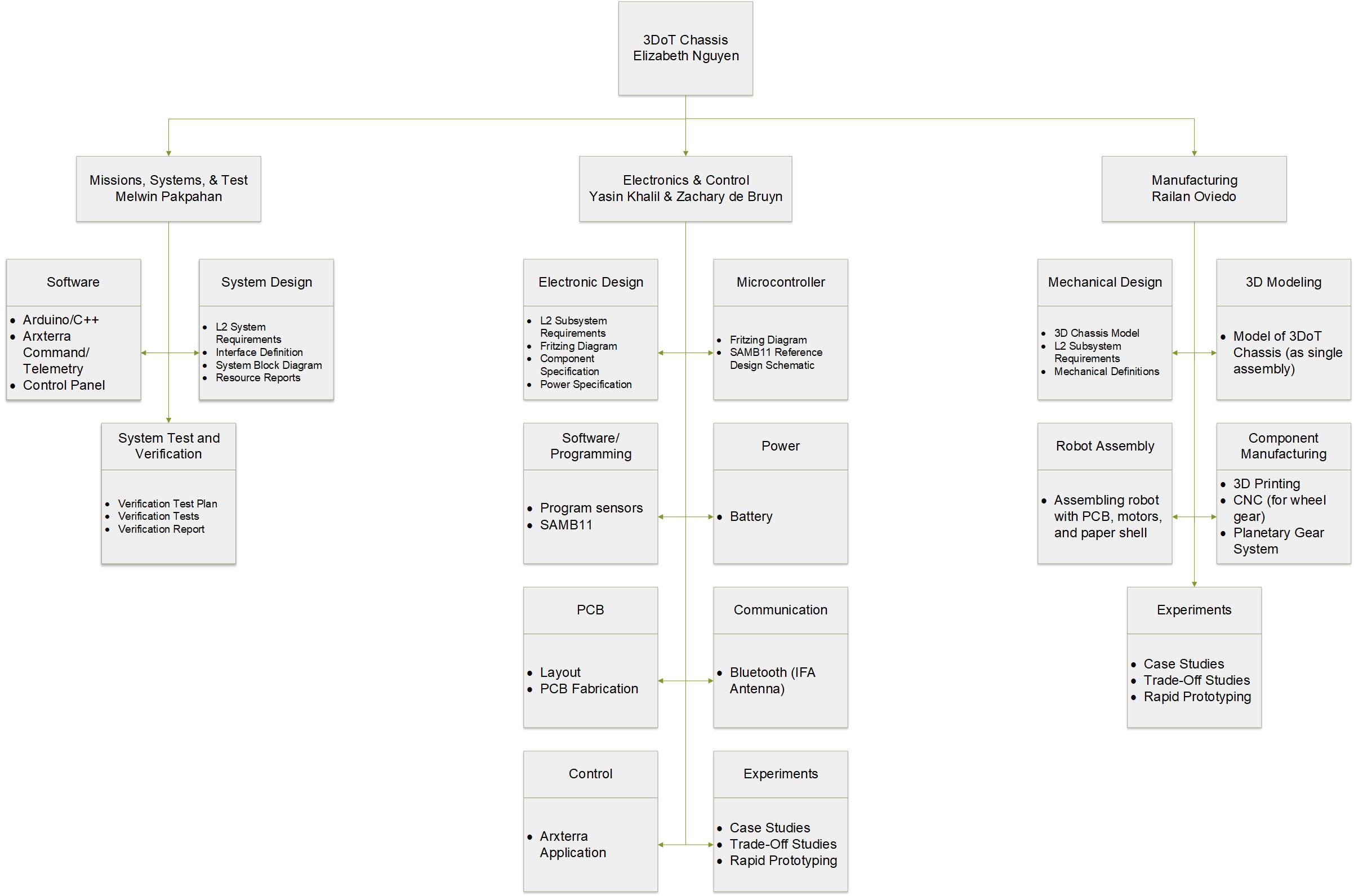
Systems/Subsystem Design
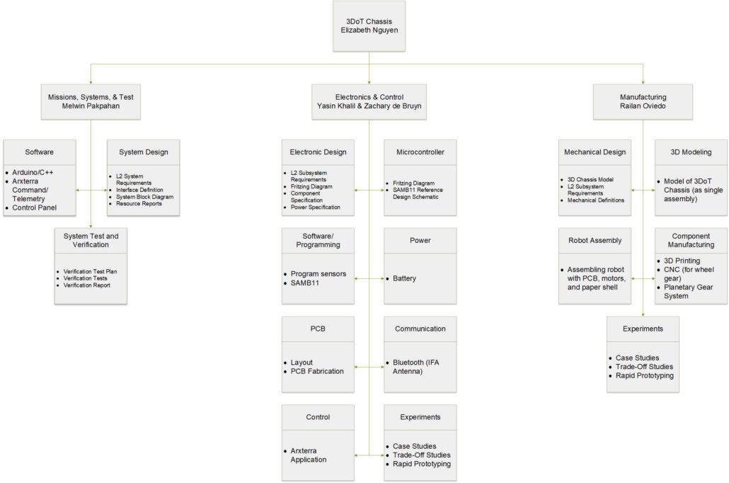
Product Breakdown Structure
Created by Melwin Pakpahan
Electronic System Design
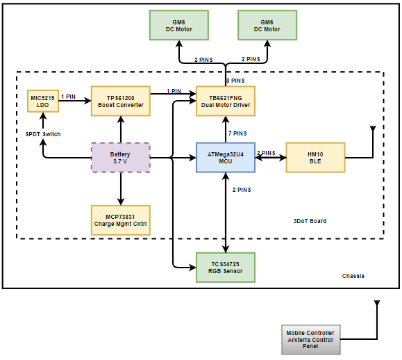
System Block Diagrams
Created by Zachary de Bruyn

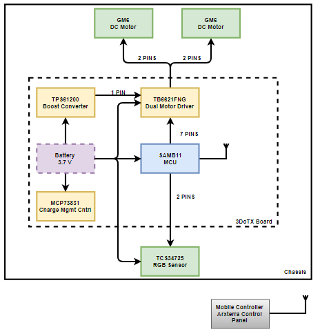
System Block Diagram for 3DoT Board

System Block Diagram for SAMB11 Board
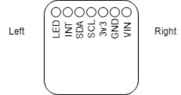
Interface Definitions
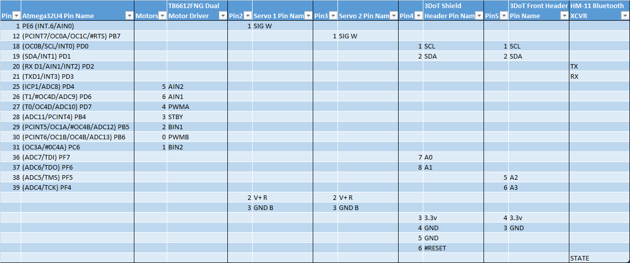
3DoT Interface Definition
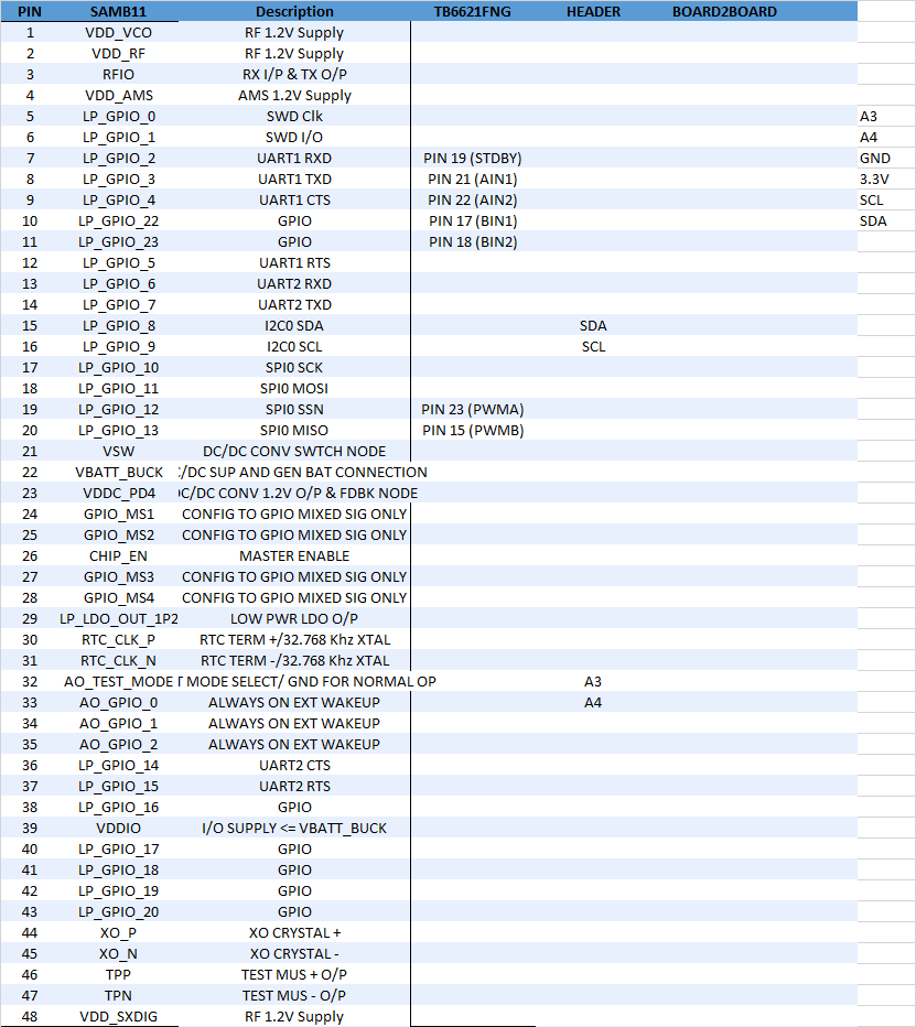
SAMB11 Interface Definition
Mechanical Design
Written by Railan Oviedo
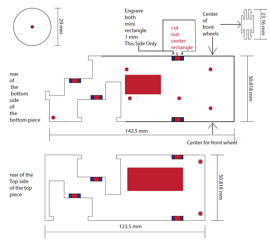
For this version of the 3DoT Chassis, the customer’s biggest requirement is to have it 3D-printed as a singular piece. This varies from the previous iterations, as they had each required an assembly of the chassis first. In order to realize this, I will have to adjust the previously made 3D modeled parts and combine them in such a way that the entire chassis can printed at once.
To avoid long print times—and thus a higher chance of an error while printing—the chassis’ front and back will have to be perforated so as to avoid printing unnecessary space. To comply with the boundaries made by the Prospector Pete paper structure, the Chassis size will not exceed measurements of 4 x 3.5 x 3 inches. Furthermore, the primary method of movement will be realized through the use of a planetary gear system. The inner workings of the Chassis will remain relatively the same from the previous plastic design. That is, there will be grooves to hold in the 2 DC motors and the 3DoT board, which will have a battery and circuitry for the robot placed onto it. The final aspect of the 3DoT Chassis will involve a shield placed in the front in order to allow for placement of sensors and navigation along with a castor wheel for counter-balance purposes. This shield will also serve as a stand for a phone that can be placed on the chassis.
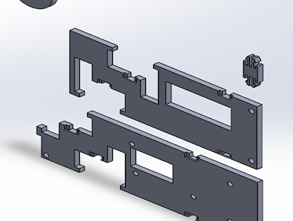
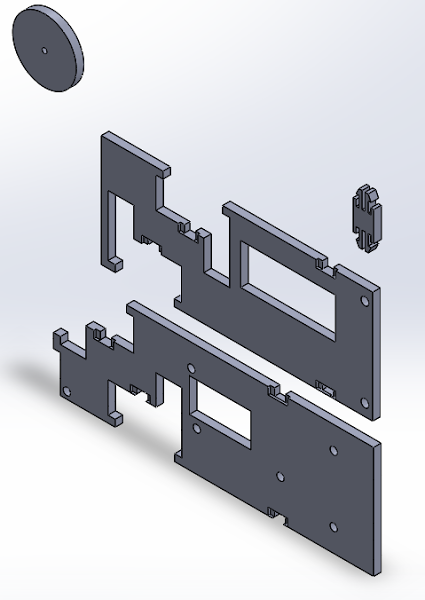
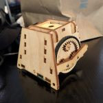
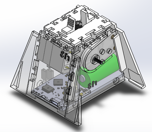
The following images show what the general shape of the chassis looks like from a diagonal view, side view, and front view:

3DoT Chassis Diagonal View

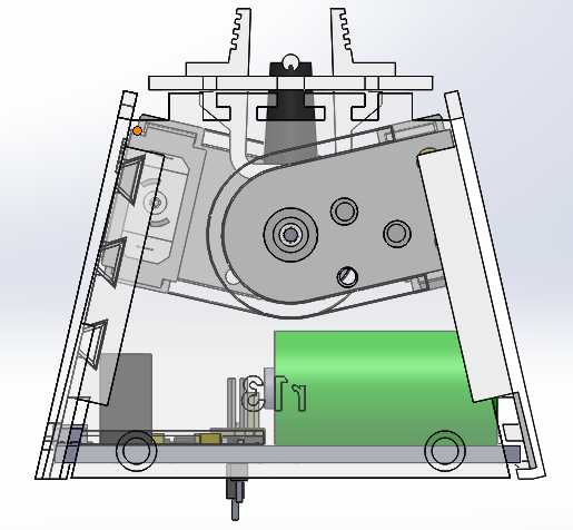
3DoT Chassis Side View

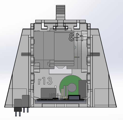
3DoT Chassis Front View
Design and Unique Task Descriptions
Manufacturing
3D Printed Chassis
Written by Railan Oviedo
As previously stated, a singular design of the chassis can be modeled through referencing the previous models made by prior teams that worked on the 3DoT. The major goal for the completed 3D chassis design is to be able to be printed in less than 6 hours, so as to ensure that the printed chassis will not experience structural failures.
Because this version cannot be disassembled, the issue of placing the motors in comes into play. To circumvent this problem, I am planning on creating rectangular holes on the front and back of the chassis in order to easily insert the motors onto their slots. This solution would not only resolve the motor placement issue, but also reduce the necessary printing time for the chassis.
In regards to the planetary gear system, it is imperative to make sure the gears can fit within the primary wheel’s 5.5 cm diameter. The current plan is to create a triangular gear train with 3 large gears that are each attached to a smaller gear that serves as the center focal point. This setup should result in little to no loss of rpm between the large gears, as they are the ones that will be connected to the primary wheel.
An expected completion date for a 3D model design is October 25, 2017.
Electronics & Control
Inverted-F Antenna
Written by Zachary de Bruyn
The 3DoT Chassis team will be implementing two varieties of “3DoT” boards. One board will consist of the heritage 3DoT ver. 4-54 board which utilizes the ATMega32U4. In order for the heritage 3DoT to communicate with peripheral devices, an additional component, the HM10, is needed to provide a 2.4GHz link between a transmitter (XMT) and the HM10. The second board, however, utilizes a SAMB11 SoC. Within the SAMB11 is the BLE device necessary to communicate at 2.4GHz, but requires the design and implementation of an antenna external to the SAMB11.
Implementation of an antenna design is dependent on the frequency at which it is to receive. Therefore, in order to implement a PCB antenna which utilizes the 2.4GHz, which bluetooth is dependent on, we are limited to only a couple of antenna varieties [1]. In short, the Inverted-F Antenna (IFA) was chosen for a couple of reasons: 1) It is similar to the design of the antenna on the HM10, which is a proven concept; 2) the IFA is isotropic allowing for reception from a wide range of three-dimensional locations, and 3) it allows for 2.4GHz reception. The expected completion date is November 1, 2017.
References:
[1] http://www.ti.com/lit/an/swra161b/swra161b.pdf
[2] http://www.ti.com/lit/an/swru120c/swru120c.pdf
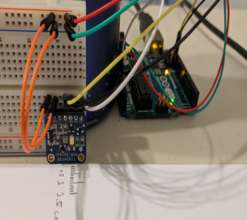
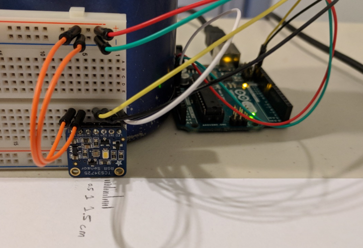
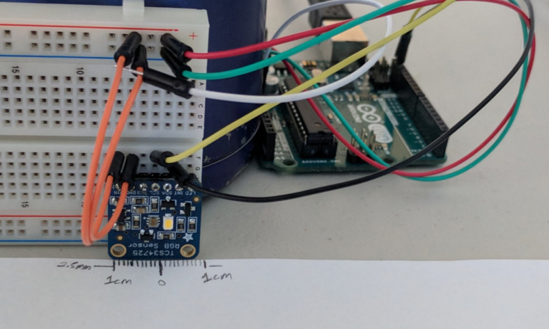
Color Sensors (TCS34725)
Written by Zachary de Bruyn
It is the goal of the 3DoT team to implement the Light-to-Digital Converted (RGB Sensor) in order to read the different colors that are imposed on the maze/roadway in order to navigate the maze autonomously. The benefit of using the color sensor is that it will allow the toy robot to use the color values it evaluates to maintain the direction on the maze. We can then implement a controlled response that will allow the toy robot to correct its direction based on interference from other undesirable colors. There is an expected completion date of November 15, 2017.
References:
[1] https://cdn-shop.adafruit.com/datasheets/TCS34725.pdf
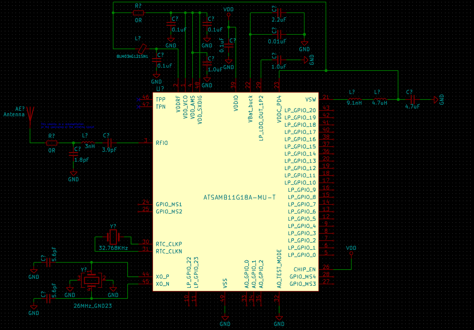
SAMB11
Written by Yasin Khalil
The SAMB11 will be implemented in custom PCB to replace the heritage 3DoT ver. 454 board that utilizes an ATMega32U4.
The SAMB11 will provide all of the base features as the ATMega32U4 in the original 3DoT board. These features include a dual H-Bridge, sensors, power management (battery, usb, etc.), servo’s, and DC motors. There will also be correlating headers to that of the 3DoT to allow for seamless integration with past projects.
An expected completion date will be November 15th, 2017.

SAMB11 Reference Design Schematic
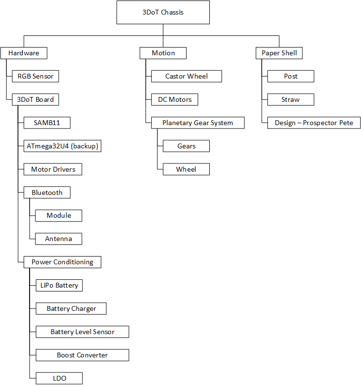
Preliminary Project Plan
Work Breakdown Structure
Created by Elizabeth Nguyen
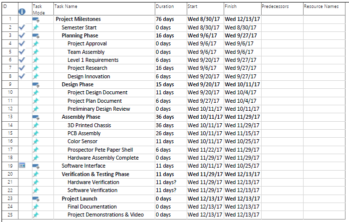
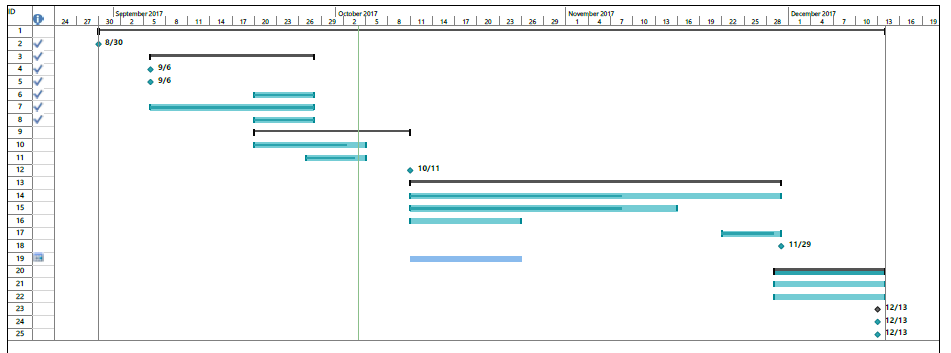
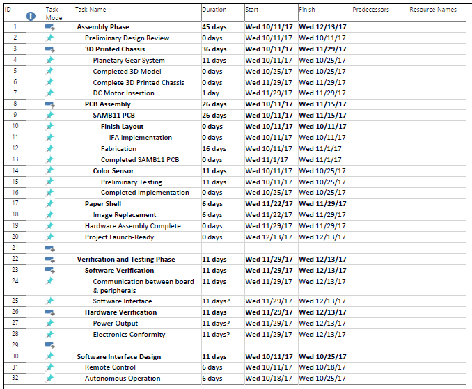
Project Schedule
Created by Elizabeth Nguyen
Top Level Schedule
System/Subsystem Level Tasks

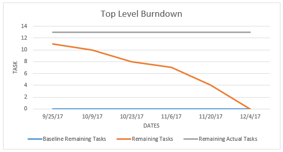
Project Burndown
The current graph shows a burndown from a top level view; however, it is difficult to ascertain the ideal burndown. It will be updated with the correct dates as well.
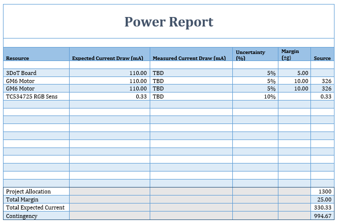
System Resource Reports
Created by Melwin Pakpahan
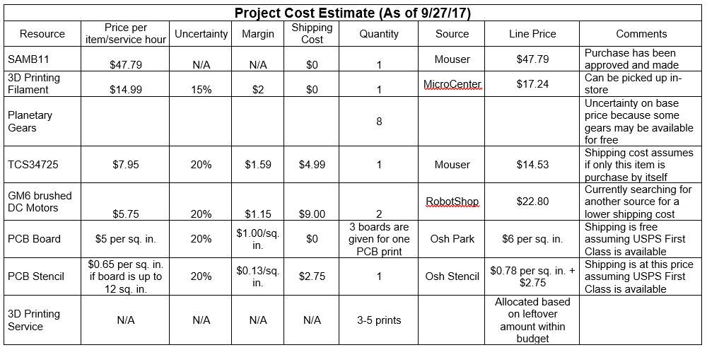
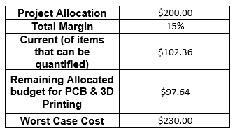
Project Cost Estimates
Written by Elizabeth Nguyen
A budget of $200.00 was projected by the customer. It is difficult to ascertain an estimated budget due to variances in services such as 3D printing and PCB board assembly. However, at least 50% of the budget is estimated to go towards physical parts and the rest of the budget will be allocated towards services.