By: Jacob Cheney (Systems)
Approved By: Alexander Clavel (Project Manager)
Introduction
During the final mission, where the BiPed will compete in the end of the semester game, it is required that our robot is controlled via Bluetooth. In order to accomplish this task, the BiPed will be equipped with a Bluetooth 4.0 transceiver that will receive commands from the Arxterra application on an iPhone. In this blog post I will be going over the design and test process that took place order to make wireless communication possible.
Custom Commands
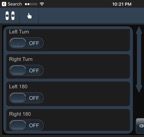
The Arxterra application is a robotics iPhone app that was specifically designed to control a robot over Bluetooth. It works by sending packets of data to the BiPed where it will then be decoded to control our system. To ensure our BiPed is receiving the correct data, we must first define our custom commands within the app itself.
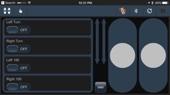
Figure 1: Arxterra Remote Control
Our BiPed utilizes 5 basic movements in order to navigate through a maze, they include walking, turning left 90 degrees, turning right 90 degrees, turning left 180 degrees and turning right 180 degrees. Because of this, we must create 5 custom commands to distinguish each function from another.
Within the app, each movement is assigned to a specific command ID. For our BiPed, the assignments are as follows:
| Custom Command |
Command ID |
| Walk |
0x01 |
| Left Turn |
0x41 |
| Left 180 |
0x42 |
| Right Turn |
0x43 |
| Right 180 |
0x44 |
Once the custom commands are defined, the app is ready to begin transmitting data. In order to actually do anything with these commands, we must now program the BiPed to decode the data packets.
BiPed Firmware
In this section I will go over the BiPed code and how it translates the incoming stream of data.
First we defined variables within the Arduino code that correspond to each command.


Next, within the CommandDecoder subroutine, every command packet the BiPed receives is broken down into individual bytes and read into an array called data.
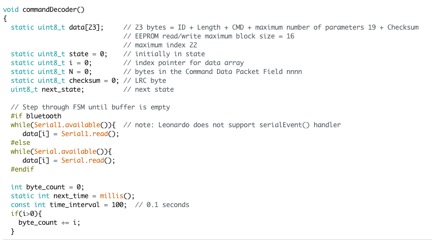
Then the CommandHandler subroutine is called and assigns the variable cmd to equal the 2nd byte within the data array, this is where the command ID byte is found. Finally using if-else statements, the code is configured to call each movement subroutine based on the Command ID that was sent. This is shown below.

Looking at the code, you can see that I added Serial.print’s before every subroutine is called. This was used during the test phase to ensure the correct subroutine was being called when each command was sent.
Conclusion
After initializing all of the command variables and implementing a series of conditional if-else statements, the BiPed is now able to communicate wirelessly with the Arxterra app.


