Spring 2017 Velociraptor: Fritzing Diagram

Table of Contents

Authors

By: Mohammar Mairena (Electronics & Control Engineer)
Approved By: Jesus Enriquez (Project Manager)

Introduction

Before one can create a custom printed circuit board (PCB), one has to create a Fritzing diagram. A Fritzing diagram is a virtual electronic circuit that is modeled after a circuit tested on the breadboard. Fritzing is used to provide the layout of the breadboard given the tools needed for a future PCB design.

Fritzing Diagram

The diagram shown is the Fritzing diagram our group used for the Preliminary Design Review (PDR). The diagram is a very rough idea of the parts we are using for the final schematic. This diagram is meant to provide a general idea of the parts needed for the final PCB design. Each part shown serves a purpose.

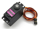
The breadboard consists of the 3Dot board, three servo motors, two DC motors, an external battery, an A/D converter with rotary/shaft encoders, an additional low-dropout voltage regulator for the extra servo motor and a GPIO expander. Two DC motors are used to control the legs of the raptor, one servo motor to control the head and another to control the tail. The extra servo motor will be used to control the turning motion of the Velociraptor. Since the 3Dot board is only capable of utilizing two servo motors and two DC motors, a PWM expander is necessary for our additional servo motor. The PWM/Servo driver is not shown and should replace the GPIO expander in the design. The PWM/ Servo driver with i2C interface has the capacity to add extra servos through two pins, SDA & SCL (Data and Clock).


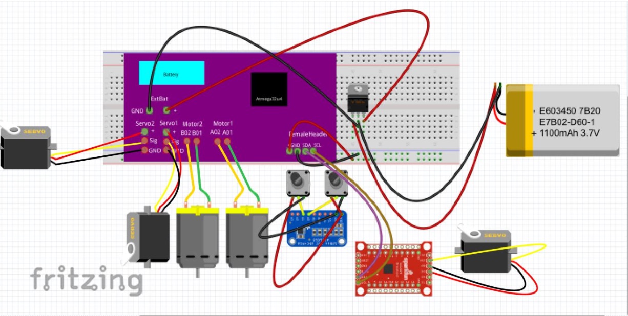
Note: The 3Dot board was taken from Fall 2016 Velociraptor’s fritzing diagram.

Resources

  1. http://web.csulb.edu/~hill/ee400d/Technical%20Training%20Series/07%20FritzingDocumentation.pdf        
  2. https://www.arxterra.com/fall-2016-velociraptor-w-fritzing-diagram/ 

Spring 2017 Velociraptor: RGB Color Sensor

Table of Contents

Authors

By: Mohammar Mairena
Approved By: Jesus Enriquez

Introduction

The Velociraptor will compete in a game similar to Pacman. One of the requirements is that the Velociraptor shall attempt to collect as many red dots as possible while navigating the maze utilizing either a static or dynamic walk. As a result, we will be using an IR sensor to detect the dots in the maze. My choice for the color sensor is the Sparkfun RGB Color Sensor. The reason I chose this specific sensor (APDS-9960) is because of the detection range and the operating voltage at 3.3 volts. In comparison to other sensors, this one has a lengthy detection range of 4-8 inches.

Analysis

The SparkFun sensor includes examples of Arduino library code for color sensing and proximity detection. I tested the color sensor and proximity sensor with the library code. After hooking up the sensor to the breadboard and uploading the code, I placed different colors up to the sensor. I had a hard time distinguishing colors using the serial monitor on the Arduino interface.

Conclusion

In retrospect, the SparkFun RGB Color Sensor is an ideal infrared sensor for the Pacman game however, detecting the different colors (red, blue, green) proved to be very difficult. Another disadvantage of this sensor is that it is very miniscule and would only detect the red dots if they were large in size. Completing this experiment helped me realize how minute the sensor was and how important it is going to be to correctly place the sensor on the robot.

Resources

  1. https://www.sparkfun.com/products/12787

Spring 2017 Velociraptor: SolidWorks Hardware Design Model

Table of Contents

Authors

By: Andrea Lamore (Manufacturing)
Approved By: Jesus Enriquez (Project Manager)

Introduction

Throughout the engineering design process, the SolidWorks model for the Velociraptor went through a series of changes as our team went through trial and error with the different components for the robot. This post includes some of the thinking that went behind the hardware design of the robot.

Hardware Design

Servo Holder

Previously we planned on 3D printing and ordering all the parts necessary to build out first prototype. I modified and added a few parts to the velociraptor skeleton in anticipation of some problems that might occur during the build phase.

Mounts for the server were added to the bottom of the velociraptor for hip movement. Two or one servos could be placed here to accomplish hip rotation.

Head & Tail

Horizontal ball bearing will be used to facilitate rotation of the head and tail and the hip. The weight of the velociraptor is being supported by the legs, meaning that the body will resting on the hip mechanism which is attach to the legs – bearing will be added along the shaft of the hip that attaches to the leg. In order for the horizontal bearings to turn properly the outer and the inner radius of the bearing must not both be resting on the same surface. Circular extrusions for the parts resting on the bearing will be used to allow for proper slipping. The same horizontal bearing mechanism will be used to facilitate head and tail rotation.

Leg Mechanism

An issue with the Theo Jansen mechanism is the inability to keep the foot parallel to the floor is. Instead the foot moves in parallel with the legs circular motion. This means that that the whole body will shift back and forward with the foot motion when the velociraptor takes steps. With our first prototype, where we intended to use servos, a mechanical mechanism to keep the foot parallel to the floor could easily be incorporated into our design. A rounded out sole and a pair of springs attached to a pivoting joint at the angle was incorporated into the design in order to keep the foot parallel while  it is carrying the weight of the velociraptor(when it is the supporting foot being used to stand). The rubber sole will give the velociraptor height in order to prevent the toe from hitting the floor on steps and to keep the foot from slipping.


Conclusion

After going through the design process, there was still consistent changes throughout the semester in terms of Hardware design as our team consistently went through prototyping. As a result, we ended up deciding to do most of the manufacturing through laser cutting instead of 3D printing according to our original plan.

S17 Prosthetic Arm: Kill Switch Test

This test if performed to try to confirm that a switch on the V- path back to battery is able to turn off the prosthetic arm and hand system without damaging other electronic components.

S17 Prosthetic Arm: Servo Load Test

This test is done to make sure the servo in the prosthetic arm can handle the weight of the prosthetic hand and any object that it’s holding while still being about to rotate vertically, with the orientation in the direction of the ground.

S17 Prosthetic Hand: Mode Selector Test

The Mode Selector Test is done to check if we can enter different modes using the Flex Sensors that were tested in an earlier blog post to control the movements of the Prosthetic Hand by syncing different types of movements of the hand to different modes that are achieved by syncing the modes to different movements of the flex sensors.

S17 Prosthetic Arm: Battery Discharge Test

This test is done in order to choose the proper battery to use for the prosthetic arm and hand, and then to figure out how much capacity the battery has, and what the voltage rating of the battery is.

S17 Prosthetic Hand: Xbee Communication Test

We completed this test to verify the hook up of the Xbee so we can design a shield for it, as well as getting the Xbee to be able to send and receive data from a wireless source. Ex hand to foot and vice versa.

Stepper Motor Control

By Renpeng Zhang

Demoing control of a stepper motor.

Table of Contents

Overview

In this demo, I tested the 28BYJ-48 stepper motor with the ULN2003 stepper motor driver. I used one Arduino for the control of the stepper motor. Since it’s recommended to use an external power source, I just used another Arduino solely for the purpose of providing 5V DC to the motor driver. I was able to control the stepper motor to do rotate clockwise and counter clockwise.

Picture of demo

Arduino Code

Arduino code:

/*

* 28BYJ48 stepper motor code

* Connect:

* IN1>>D8

* IN2>>D9

* IN3>>D10

* IN4>>D11

* Vcc 5V source, prefered external 5V source

* Gnd

*/


#define IN1  8

#define IN2  9

#define IN3  10

#define IN4  11

int Steps=0;

boolean Direction=true;// gre

unsigned long last_time;

unsigned long currentMillis;

int steps_left=4095;

long time;


void setup() {

 Serial.begin(115200);

 pinMode(IN1, OUTPUT);

 pinMode(IN2, OUTPUT);

 pinMode(IN3, OUTPUT);

 pinMode(IN4, OUTPUT);

 // delay(1000);

}


void loop() {

 while(steps_left>0){

currentMillis = micros();

if(currentMillis-last_time>=1000){

  stepper(1);

  time=time+micros()-last_time;

  last_time=micros();

  steps_left–;

}

 }

 Serial.println(time);

 Serial.println(“Wait…!”);

 delay(2000);

 Direction=!Direction;

 steps_left=4095;

}


void stepper(int xw){

 for (int x=0;x<xw;x++){

switch(Steps){

  case 0:

    digitalWrite(IN1, LOW);

    digitalWrite(IN2, LOW);

    digitalWrite(IN3, LOW);

    digitalWrite(IN4, HIGH);

  break;

  case 1:

    digitalWrite(IN1, LOW);

    digitalWrite(IN2, LOW);

    digitalWrite(IN3, HIGH);

    digitalWrite(IN4, HIGH);

  break;

  case 2:

    digitalWrite(IN1, LOW);

    digitalWrite(IN2, LOW);

    digitalWrite(IN3, HIGH);

    digitalWrite(IN4, LOW);

  break;

  case 3:

    digitalWrite(IN1, LOW);

    digitalWrite(IN2, HIGH);

    digitalWrite(IN3, HIGH);

    digitalWrite(IN4, LOW);

  break;

  case 4:

    digitalWrite(IN1, LOW);

    digitalWrite(IN2, HIGH);

    digitalWrite(IN3, LOW);

    digitalWrite(IN4, LOW);

  break;

  case 5:

    digitalWrite(IN1, HIGH);

    digitalWrite(IN2, HIGH);

    digitalWrite(IN3, LOW);

    digitalWrite(IN4, LOW);

  break;

  case 6:

    digitalWrite(IN1, HIGH);

    digitalWrite(IN2, LOW);

    digitalWrite(IN3, LOW);

    digitalWrite(IN4, LOW);

  break;

  case 7:

    digitalWrite(IN1, HIGH);

    digitalWrite(IN2, LOW);

    digitalWrite(IN3, LOW);

    digitalWrite(IN4, HIGH);

  break;

  default:

    digitalWrite(IN1, LOW);

    digitalWrite(IN2, LOW);

    digitalWrite(IN3, LOW);

    digitalWrite(IN4, LOW);

  break;

}

SetDirection();

 }

}


void SetDirection(){

 if(Direction==1){Steps++;}

 if(Direction==0){Steps–;}

 if(Steps>7){Steps=0;}

 if(Steps<0){Steps=7;}

}

Video

Video


Solar Panel Voltage Calculations

By Edgardo Villalobos

Calculations to find what voltage and current the solar cells need to provide to charge the battery in 8 hours.

Table of Contents

Voltage

Battery 

  • Solar Panels need to be able to charge a 12-Volt, 7-Ah (10-Ah) battery

Rule of thumb 

Rule of thumb: Solar Panel Voltage = Battery Voltage x 1.5

                            Solar Panel Voltage = 12-V x 1.5

                            Solar Panel Voltage = 18-V

  • The Solar Panel needs to charge the battery in 8 hours

Current

Rule of thumb: Amps = Amp Hours / Hours

                             Amps = 7-Ah / 8-hrs            Amps = 10-Ah / 8-hrs

                             Amps = 875-mA                    Amps = 1.25-A