PCB

By: Victoria Osaji, Manufacturing and Development Engineer

Table of Contents

Introduction:

A printed circuit board (PCB) also known as a printed wiring board is used to build the infrastructure for electronic devices. The purpose of this infrastructure is to mount components and provide the electrical connection between the components in our system, which in our case is the 3DOT board.  As part of the subsystem requirements provided: L1-9 Custom PCB-3rd Generation Velociraptor (Th) Project Schedule shall use an external PCB with an I2C Interface (JP5) as the 3DoT Board.


Process:

schem

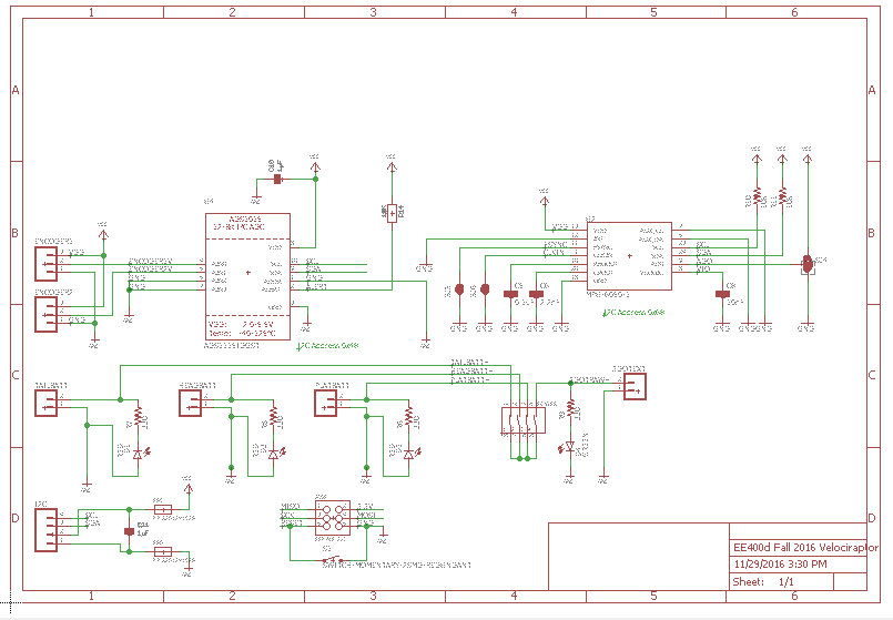
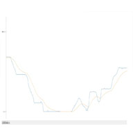
Figure 1: The schematic provided by the E&C that needs to be designed into a PCB.


To design the PCB I used the software Eagle CAD program. I was first given a schematic by our electronics and controls engineer to make into a PCB layout for our project. I imported the schematic and switched it to a board.

3dot-pcb

Figure 2: The Screenshot of the connections between the PCB and the 3DOT board after being imported into Eagle CAD


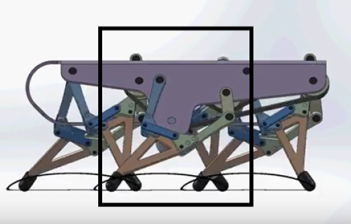
For our project, our PCB had to be designed like a shield for the 3DOT board because of the location we were placing it in. We made the decision to place it right over the square area for the body. As a result of this feature, I needed to make sure that I had made the size and the connections from the 3DOT to the PCB as accurately as possible. Therefore to ensure this accuracy, I imported the 3DOT board from 3DOT library. I then overlapped the 3DOT and the PCB, got the size and connections, and then cut out the power supply part from the PCB because we will not be using it.

After getting the size and connection where they needed to be, I placed the rest of the other components according to the schematic. I tried to make all the components that were connected to each other close to one another. After the placement of the components or ICs, I began to wire. When wiring I made sure to follow the requirements made by the customer.

wiring

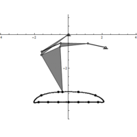
Figure 3: Screenshot of what the wiring process looks like.


After wiring up everything I ran a couple of design analysis checks to make sure everything required of me and the PCB was met. Then I put some more finishing touches such as copper, the inscription of our project name and class, etc.  Since everything was cleared, I got my board approved and then ordered it. Always ensure to order the PCB at least three weeks before the week of the final assembly, especially if ordered by OSH Park, it does take a while to make and get shipped. Also, you would have to solder the board after, so make sure to order the components/parts on the schematic.

Conclusion:

finished

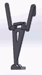
Figure 4: Screenshot of what the final product looks like with the copper and the etching.


All in all, the PCB layout wasn’t hard in its design but time consuming in its conception. Ensuring that I had the right parts in the right location was crucial to the overall success of completion of the PCB. Once it was been determined the reason and overall concept for  the PCB design, it was easy and quite fun to do. Thank you and Good luck!


Citation/Guided References:

https://learn.sparkfun.com/tutorials/using-eagle-board-layout

https://www.arxterra.com/printed-circuit-board-pcb-how-to-layout/


Mechanical Design:

By: Victoria Osaji, Manufacturing and Development Engineer

Introduction:

After a lot of trial and error and prototyping, we have the basis for our mechanical design. Listed below we explain how we achieved each part.

Level 2 Subsystem below:

3. 3rd Generation Velociraptor (Th) should resemble a Velociraptor of the Theropodous Dinosaur Suborder that is scaled down to below the height of the columns in the game.

8. 3rd Generation Velociraptor (Th) shall use a single servo to control the head and tail.

body

Figure 1: These are different views of our robot without the head and tail.

Body:

The body of the robot was designed with a couple of things in mind. We knew we wanted all the components such as the 3DOT board, PCB, the 2 servos and the 2 GM9 motors to be able to fit within the body so we made the robot approximately about 100mmx52mmx48mm. The thickness was based on the wood we used which was Balsa and it was .3175mm thick.

top

Figure 2: This is a top view of our chassis. The biggest hole is the hole for where the servo is located.

On the top chassis, we designed a hole about 13mm for one of the servos that is going to be connected to the gear train that will move the head and tail [L2-8]. We made that hole because we wanted all of our gears to be flush on the body and we were able to achieve that with the hole of the top.

side

Figure 3: This is a side view of our robot. The biggest hole is the hole for the GM9 motor the other three holes at the top in a row are for the gears.

On the side chassis, we have different holes for the gear train 3mm that will be controlling the legs and the hole for the motor couplers that connect to the GM9 motors were 7mm.

toptop

Figure 4: This is the cover that went over the head and tail to keep the gears flush on the top.

On top of the top chassis we have a piece that was created to hold the gears in place and this piece consist of ten 3mm holes. The body was designed to be pressure fit to avoid using adhesive hence why there are cut of rectangles on certain pieces and extruded rectangles on others so they can mate into each other.


Gear Train:

sidegear

Figure 5: This is gear train for the legs on Solidworks.

The big gears have 16 teethes and the small ones have 10 teethes. Two big gears and 2 small gears will be used to make a gear train for our mechanical systems. The big gears have 3mm holes in them so they can be connected to the legs. Calculations had to be done to determine the gear ratios. (Click here hyperlink to blog post)


Motor couplers:

motor-couplpermotorcoupler2

Figure 6: These are the small gears also known as the motor couplers for the GM9s and the rotary sensors.

The motor couplers were made to be connectors from the GM9 motors to the rotary sensors to the legs. They were made in form of gears because we need the motor to drive the gear train for the legs to move. On one side of the motor coupler we have an extruded cut piece 6mmx5mmx3mm to fix the GM9 motor and on the other side we have an extruding shaft for the rotary sensor. It was a circle with a diameter of .125mm cut in a shape of a “D”. This motor coupler goes into the small hole of the side chassis.

Legs:

leg

Figure 7: This is the final design for the legs.

The final design for our legs was two links connected in a “T” shape with a square platform as the foot.  The links are about 15mmx 54mm with 3mm holes. The holes on the legs are connected to the smaller holes on the big gears. The project manager, Paul actually came up with this design because it would be easy to control on the electrical side. We had about 3 other leg designs before we came to this one. Click here to see the leg journey.


Head and tail:

head

Figure 8: To the left is the piece that we used for the head and tail. To the right is the gear train for the head and tail.

The head and tail design was motivated by the requirement to use a single servo to drive the head and tail. The design was simply a gear with 9 teethes on one half and the other half of the circle or gear was elongated about 50 mm into a flat board (.00125mmx.00075mmx.00025mm) for our battery holders (like the picture to the left). Then in between the head and the tail were two small gears with 20 teethes each.

 material

Materials:

Figure 9: These are the materials we ending up using, balsa wood and PLA Filament plastic.

At first we wanted to 3D print our whole robot but we when we prototyped our robot leg with laser cut wood we really liked the appearance of it. Then we processed to laser cut the body just to test it out and we really liked it. We liked how precise it was and the ability to pressure fit with it as oppose to 3D printing. We had a lot of issues 3D printing because I would design something and the 3D printer would print it but the part would shrink or wouldn’t fully print certain parts especially if they were small parts. With laser cutting I was able to design the part with exact dimensions because the laser cutter was very exact. We still 3D printed the gears and the motor couplers because those parts are 3D and the laser cutter only cuts in 2D.

(Link to material trade off study blog post)

Conclusion:

All in all, these are the major things that helped our project come together. This design is simple and it work.  T  he thing I learned the most is rapid prototype early and have back-ups. Just because something works on solidworks doesn’t mean it is going to work in the physical world. It might be frustrating but when it all comes together trust me, it will all be worth it. Good luck!

Coverage Angle Test

By: Victoria Osaji, Manufacturing and Development Engineer

Table of Contents

Design Analysis:

Introduction:

This was one of the four tests we conducted to demonstrate the mechanical capabilities of our robot dinosaur. In this test we are looking to determine the radius our robot head can cover essentially measuring what areas our robot can see as it moves its head around. This way we know the limitations on the robot head so as not to damage any of the linkages or the internal components which are tied together

Process:

 coveangle

Parts needed:

  • Flat surface area
  • Protractor to measure out the radius angle
  • Ruler


In order to measure the coverage angle the steps and measures we took are show below:

1. Set your robot head to the middle of your robot and mark that distance
2. Move your robot head as far to the left as possible without moving the body. Mark that spot.
3. Move your robot head as far right as possible without moving the body. Mark that spot.
4. With a protractor measure the angle covered from the left to the right.
5. This is the range that your robot can visually cover.

We repeat this exercise a few more times to validate the range we are getting on the robot


Results:

What we noticed is our robot moved 160 degrees to the right when turned and in the reverse direction 20 degrees to the left when turned. On average the consistent rotational angle we saw was 140 degrees. We repeated the exercise and had several numbers in ranges of 138degrees all the way to 142 degrees (we had about 8 different tests conducted). Therefore our 140 degree was an average of the all the samples we attained.

Conclusion:

All in all, there are several important factors for why we want to know what our coverage angle. We do not want damage linkages or any parts of our robots by awkwardly turning it in directions it is not able to go. Therefore understanding what our limitations are with regards to knowing what our coverage angle is will help to protect our robot.

Load Capacity Test

By Victoria Osaji, Manufacturing and Development Engineer

Table of Contents

Introduction:

This was another one of the four tests we conducted to demonstrate the mechanical capabilities of our robot dinosaur. In this test we are looking to determine the load the robot can sustain without any significant damage or falling apart. This way we know the limitations on the robot support so as not to damage any of the linkages or the internal components which are tied together or put unnecessary strain on the legs.

Process:

load1

Figure 1: One of the load tests conducted on our robot.

Parts needed:

  • A bowl to hold the load
  • A system of weighted measure (in our case we used cups of rice)
  • A scale to measure the weights
  • A flat surface to balance your robot


load2

Figure 2: Another one of the tests conducted. Using a heavier weighted sample

In order to determine what the load capacity of our robot was, the steps we took were:

1. Get pieces of wood with varying weights. (Always better to use a flat piece of wood but you can also use a flat piece of metal or any weighted substance – we used a bowl of rice)
2. Weigh the piece first and then place on top of robot.
3. Ensure that your robot maintains its balance and doesn’t tip over.
4. If it doesn’t lose the support, move on to another piece of wood. One that is preferably heavier than the last one used.
5. Continue this until your robot shows fatigue or an inability to maintain support.

Results:

Our tests results showed the following:

Weight 1 200g
Weight 2 383g
Weight 3 570g
Weight 4 761g
Weight 5 950g
Weight 6 1.25kg
Weight 7 1.54kg
Weight 8 1.745kg


At about weight 8 we started to see a significant dip in the legs of our robot where it started to diminish.  This is where we noticed our first major pressure point. As a result of not wanting to have to put our entire robot all over again from scratch we decided that this would be the load capacity for our robot.


Conclusion:

The load capacity is extremely important to the overall weight and support of the entire robot. It is important to note the limitations on what your robot is capable of and what your robot is able to lift and support that way we don’t compromise the entire structure of the robot.


Design for Feet Trade-Off Study:

By: Victoria Osaji, Manufacturing and Development Engineer

Introduction:

The foot of the raptor is probably the most important piece to the animal. This determines the most support for the center of mass and gravity for the raptor. Based on this ideology, we thought about three different types of design for the foot of our raptor.

Level 1 System below:

S1. The 3rd generation velociraptor shall statically walk on a flat surface of linoleum

S2. The 3rd generation velociraptor shall statically walk on a flat surface of cardboard.

S3. The 3rd generation velociraptor shall statically walk on an incline and decline surface of 6.5 degree maximum

S4. The 3rd generation velociraptor shall perform static walking while on a step of .5cm.

D1. The 3rd generation velociraptor should statically walk on a flat surface of linoleum

D2. The 3rd generation velociraptor should statically walk on a flat surface of cardboard.

D3. The 3rd generation velociraptor should statically walk on an incline and decline surface of 6.5 degree maximum

D4. The 3rd generation velociraptor should perform static walking while on a step of .5cm.

For one design we thought of a splined/sloped design. We decided that a curvature at the bottom of the feet may allow the best stability for our raptor. We tried to simulate the feet of humans in this scenario. Most human feet are actually not flat and are more or less splined or curvy and we figured we would duplicate this idea in creating our raptor. The advantages to this idea were minimal at best, while it was the most similar to humans it didn’t offer as much support or foundation for the center of mass for our raptor and when looking at it mechanically it actually would not be easiest design to translate mechanically.

For another design, we thought of a flat surface as the base of the foot of the raptor. In order to support the weight of the raptor we decided that we would need a square base foundation that would support that weight. Also we felt that we would be able to ensure that our raptor would be able to balance better in case of a battle with another dinosaur. However we notice that there would be discrepancies with this design. In the event of a battle, as much a flat base may not provide the best balance, while it would provide some balance it may not be the best. Also when it comes to navigation, a flat surface base as the foot may not provide the best grip for unlevelled surfaces, this may cause the raptor to tilt and fall in areas as such. So then we thought why not a flat surface with spiked feet. This would still give us the strong square- base foundation to which our raptor would be supported which is based off the weight of our raptor as well as the benefits of having spiked feet. With the spiked feet, we would allow the dinosaur to have enough grips as it navigates through different locations. It would also allow for the raptor to use as a weapon in case of a battle. Ideally, this would make the most sense and would satisfy all the components we are looking for our raptor to have.

References:

https://www.arxterra.com/spring-2016-velociraptor-hardware-simulation/

http://sites.uci.edu/markplecnik/projects/leg_mechanisms/leg_designs/

Materials Trade-Off Study:

By: Victoria Osaji, Manufacturing and Development

Introduction:

The previous semester, spring 2016, did a very detailed material trade-off study that we liked based on Aluminum and PLA Filament (3D printing material). We found this very useful because we have ideas that we can now build off of.

Although, our design may differ in some places and our requirements have changed a bit these are still information we can use because the basics requirements are covered such as walking statically and dynamically and being able to walk up and down uneven surfaces. What I really liked most is that they used the two different materials depending on their needs. They used the aluminum for their bottom piece because they wanted to maximize the weight on the head and tail. Then they used the PLA filament for the foot that way the robot could walk statically and dynamically without slipping on different surfaces.

References:

Leg Design:

By: Victoria Osaji, Manufacturing and Development Engineer

Table of Contents

Introduction:

The legs are one of the most important and complicated parts of this project. I mean without legs or not being able to control the robot the project would not meet a lot of requirements and it would not work. So we took this very seriously.

Level 2 Subsystem below:

14. 3rd Generation Velociraptor (Th) shall have a leg design that can support the mass at 505.5g at different positions for standing, bent, and crouching.

Design 1:

legdesign1

Figure 1: This design was modeled after the UCI linkages.

These legs were the image in Figure 1. At first I was having trouble designing these legs because I didn’t understand completely how they worked. But as I did more research, I realized the UCI linkages were all about the circular motion Click Here.


legmechanism

Figure: The model for design 1.

Understanding that, I found a design to reference online. The reason we did not use these legs is because I was having issues simulating the walking pattern on solidworks, I am not sure if there was too much or too little traction. So I decided to 3D print it just to see if I can fix the issue manually. I think the problems stem from the dimensions and the sizing of the legs. I didn’t have any exact measurement, I just eyeballed it and you cannot do that with these robots because they are very sensitive in that sense.  Fabian, the President of the Wednesday class, tried to improve this design by making his own. The appearance was better when I simulated it on solidworks the walking pattern was inversed. To conclude, we were unable to use this design.

Design 2:

The next design I modeled on solidworks also was the Theo Jensen model.

Design 3:

This design was also modeled after a model I found on youtube, the Stephenson. For this model I printed out screenshots of the legs from online and measured out every part so I could recreate them on solidworks. The legs consisted of different size triangles, 4 links and 1 one oddly shaped piece plus the foot . The holes for all the connections were 3mm. These legs actually moved on solidworks however they were not doing the complete walking motion so I 3D printed them to manually play with them and I noticed the same thing.


References:

http://sites.uci.edu/markplecnik/projects/leg_mechanisms/