Fall 2016 Velociraptor (W): PCB Layout

By: Aaron Choi (Manufacturing Engineer)

Edited and Approved by:

– Lam Nguyen (Project Manager)

– Tim Haddadian (Division Manager for Manufacturing Engineer)


Table of Contents

Requirements

L 1-9 requirement states the Velociraptor shall have an external PCB with an I2C interface which will be similar to the 3DotBoard


Introduction


To fulfill the Level 1-9 requirement, a layout of a custom PCB with Surface Mount Technology (SMT) discrete components will be implemented. This layout will be created through EagleCAD.  Once the layout is carried out, approval must be given from Professor Hill or the class President Fabian Sasuke.


Design


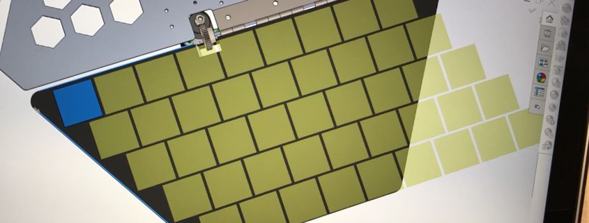
The design of the PCB layout revolved around the physical dimensions of the 3DotBoard. The idea is to place the custom PCB above the 3DotBoard. Female pin headers of the PCB will connect to the male pin headers on the 3DotBoard. The battery of the 3DotBoard limits the vertical distance from the PCB to 3DotBoard. This would affect the type of pin headers and connectors used. To avoid the physical constraints, the PCB shall have an L-shape, leaving room for pin header connections to connect properly.

figure-1

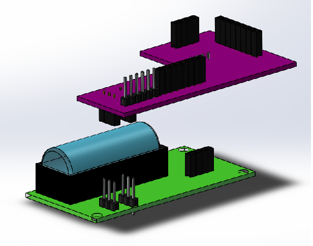
Diagram 1: The figure above shows the SolidWorks model of our PCB.

For the placement and wiring components, rules were carried out following guidelines and tutorials from SparkFun [1] and Professor Hill’s PCB training [2].  The wires were set to a 45 degree angle, the decoupling capacitors were placed close to the IC components, and none of the wiring overlaps.

The placement of the IC components were prioritized on the top layer. The reason for this was to utilize a SMT solder paste stencil for only the top layer. However, due to wiring, one of the IC components were placed on the bottom layer. The IC component placed on the bottom layer shall be hand soldered and utilizing a heat gun. The parts list chosen are given in Table 1 below.

figure-2

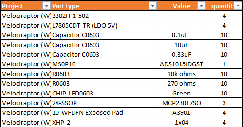
Table1: Parts list ordered from DigiKey.

The final PCB layout is given below.

figure-3

Diagram 2: The Top Layer wiring of the custom PCB.

figure-4

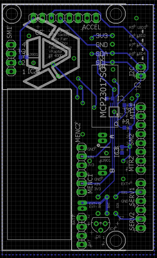
Diagram 3: The Bottom Layer wiring of the custom PCB.


Conclusion


figure-5

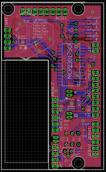
Diagram 4: PCB layout with ground planes.

Diagram 4 shows the final PCB layout for the custom PCB design. The custom PCB will be powered by 7.4V external Li-Po batteries. To bring down the voltage, a LDO was incorporated within the PCB. Stepper motor drivers were implemented for the linear actuators, which are micro stepper motors. The connectors for the IMU MPU-6050 were pin headers so that the MPU-6050 can simply be connected to the pin headers without any soldering. After running the Design Rule Check (DRC), no errors were found. The PCB will be ordered from OSH Park and an OSH Park DRC will be carried out.


References


[1] https://learn.sparkfun.com/tutorials/using-eagle-board-layout

[2] http://web.csulb.edu/~hill/ee400d/Technical%20Training%20Series/11%20PCB%20Layout%20with%20Eagle%20CAD%20(Working%20Stencil%20Addition).pdf

Fall 2016 Solar Panels: Requirements Update

By Stephan Khamis (Missions, Systems, and Test)

Approved by Inna Echual (Project Manager)

Introduction

This blog post contains our most up-to-date requirements for the Solar Panel system of the Pathfinder project. Within this blog post you will learn about the changes we have made since the CDR to update this document.

Updated Requirements

Solar Panel Requirements

  1. The Pathfinder shall be self-sufficient using solar panels.
    • According to accuweather the sun rises at 6:50 AM and sets at 4:46 PM on December 15, 2016. The Pathfinder will start to explore at 2:45 PM.
    • Starting at 80% battery life, the Solar Panels shall be able to charge the battery system to 95% in under 8 hours.
      • The solar panel shall be wired to produce at least 12 Volts and 300 mA to charge our battery system.
      • The battery will have a charge controller to prevent the battery from exceeding 12 Volts of charge, which is the maximum capacity of the battery system.
  1. The solar panels shall be able to enter and exit a cocoon state.
    • The motorized folding mechanism shall be done using a stepper motor, a motor bracket, a worm gear, and a piano hinge for each of the 3 folds.
  2. The Solar Panels will have a fixed north/south orientation for the panels to track the east to west movement of the sun.
    • Two main side panels consisting of two smaller panels shall articulate with the sun using stepper motors specified to handle 1188 oz/inch.
      • The solar cells should be used to measure and compare the voltage at an angle using a voltage divider.
    • The Solar Panels will be able to withstand 50 lbs, under the force of gravity.
  3. The form factor of the Solar Panels shall be identical to that of the Spirit and Opportunity
    • Six panels shall be cut proportional to the six panels on the Spirit and Opportunity
    • The solar panels shall use 39 mm x 39 mm polycrystalline solar cells to accommodate the customized shape of the Spirit and Opportunity
  4. The Pathfinder will be able to fit into the east most cabinet in ECS – 317.
    • The Pathfinder shall have dimensions no greater than 19” x 34” x 26” in its closed cocoon state.
    • The Solar Panel component of the Pathfinder shall be able to be added and removed from the Chassis within 20 minutes (wiring and mechanical), without the use of power tools for future separate usage of the Chassis and Solar Panel system.
  5. The Pathfinder shall have requirements agreed between both the Solar Panel and Chassis group within the Interface Control Document (ICD).
    • The Solar Panel group will provide 5.76 inches from the front top plate towards the center to accommodate the placement of the Chassis’ Pan & Tilt Mechanism.
    • The Solar Panel group will provide an availability of 10 inches between side panel motors required by the Chassis group.
    • The base of the Solar Panel will have four equally spaced 0.5” holes to establish a concentric interfacing point with the Chassis
    • The Solar Panel group will be allowed a power allocation of 2 Amps at 12 Volts, while the Chassis group will be allowed a power allocation of 11.4 Amps at 12 Volts.
    • The Solar Panels will not exceed 50 lbs as required by the Chassis group.
  6. The Pathfinder should be able to ride itself back up using the side Solar Panels and Custom Command; Cocoon.
  7. The expenses of the Solar Panel system should be limited to $200.
  8. The Solar Panel System shall be completed by December 14, 2016.
  9. The Solar Panel system shall use a custom PCB.
  10. The Solar Panel system shall use custom commands.
  11. The Solar Panel system should use custom telemetry.

Above are the Solar Panel system’s most up-to-date requirements. These requirements are more than just sentences asking what needs to be done, they’re directing the path we are taking in order to complete this project. These are requirements that we must meet and must be able to verify and validate. Requirements must satisfy two of three questions:

  1. Is it verifiable?
    1. Meaning is this a requirement that we are capable of verifying?
  2. Is it quantifiable?
    1. Meaning is this a requirement that we can quantify in numbers and test.
  3. Is it realizable?
    1. Given the fact that we have only 16 weeks in this course to design and build, some things just aren’t realizable to do within that timeframe.

Throughout the semester, we have been refining our requirements and finalized them by CDR. But, after speaking with the customer, president, and systems divison manager, we added a few requirements that would help us in creating a test plan. The added requirements are the last few; 7-12. These are requirements to help show that we will have the project completed by a certain date, under a budget, interfacing requirements, and some custom commands/telemetry the customer would like.

Past Requirements 

As stated before, we have added quite a few requirements since CDR. These requirements stemmed from speaking with the customer, president, and systems division manager while creating a test plan matrix for the final on December 14 & 15, 2016.

Future Updates

As of now, we have no plans to updating or changing anything. But, to speak for what I think should be done in the following semester, there could be work done. I believe these are decent requirements but, they are not perfect.

Fall 2016 Solar Panels: System Block Diagram Update

By Stephan Khamis (Mission, Systems, and Test)

Approved By Inna Echual (Project Manager)

Table of Contents

Introduction

As a result the feedback we received during the critical design review (CDR), we decided the system block diagram for our system. This blog post contains our most up-to-date system block diagram for the Solar Panel system of the Pathfinder project. Within this blog post you will learn about the changes we have made since the CDR to update this document.

Previous System Block Diagram

sybd_cdr

Figure 1: System Block Diagram Presented During CDR

Figure 1 shows our the System Block Diagram that we presented during our CDR. The first major difference we had to make was the switch from an Arduino Leonardo to an Arduino Micro. Per the customer, the use of the MPU – 6050 was told to be removed because the panels never had an explicit requirement for autonomous recovery if the rover fell over. We also added around 32 solar cells to help us make our 12V 1A mark of charge to charge our battery system. We also decreased the number of motorized folds to 3 rather than 5 because the stepper motors on the sub sided panels would be completely destroyed if they tried to recover the rover to an upright position.

Updated System Block Diagram

sbd_updated

Figure 2: Updated System Block Diagram

Figure 2 shows our solar panel system’s updated system block diagram. The system block diagram explains an overall understanding of what the Solar Panel system entails. Because the pathfinder is an integrated project,  also includes a portion of the Chassis system and how we are interfacing with one another electronically and a legend on the top right to help detect what the different colors and arrows mean.

On the left-hand side, you will notice the Solar Panel System, and on the right-hand side, you will notice the Chassis system. Since the Solar Panel is our priority and project, it is much more detailed than the basic interfacing that is shown on the Chassis system. Both the Solar Panel and Chassis system are using an Arduino But, the Solar Panel is using an Arduino Micro rather than a Leonardo. The two Arduinos will be interfacing with one another via an I2C. We also decided to add an MPC-23017 in order to make room for our reed switches, which will be used to prevent the cocooning mechanism from hitting the adjacent panels, which can possibly damage the cells.

Looking on the left-hand side of the overall System Block Diagram, it shows the power connections between the solar cells, battery, Pololu – A4988 motor drivers. Connecting to the motor drivers are the 3 stepper motors that will be used to help cocoon the Solar Panels. Connected to the solar cells is a charge controller that will help prevent the solar cells from providing more than 12V of charge, which is the maximum capacity of the battery.

Now looking at the right-hand side you will see the interfacing and communication going on between the Chassis and Solar Panel systems. Through the I2C connection of the Arduino Leonardo and Micro, the Leonardo will be able to help send commands to our Arduino Micro using the Arxterra Application/Control Panel. The Arxterra application will be controlled through an Android phone (Provided by the Chassis group) and will connect to the Arduino Leonardo via HM-10 BLE Bluetooth.

Future Updates

As of now, there are no future updates that I plan to change within the now updated System Block Diagram.

IMU System Incorporation

By: Paul Ahumada, Systems Engineer

By: Kevin Armentrout, Electronics and Control Engineer

Table of Contents

Introduction

As shown in a previous blog post, IMU accuracy has already been verified. The point of this blog post is to show the integration of the IMU into Arxterra as custom telemetry.

Previous Results

The IMU produced the following errors when compared to expected values:

IMU Testing
Test X Y Z
Steady State 0.113° (MAE) 0.02° (MAE) 0.13%
6 Degree Decline 0.54° (MAE) 2.60% 0.13%
6 Degree Incline 0.69° (MAE) 0.65% 0.14%
20 Degree Roll Left 0.67% 0.58° (MAE) 1.14%
20 Degree Roll Right 1.13% 0.40° (MAE) 1.67%


The IMU had excellent accuracy when compared to actual values, making it the ideal selection choice for the I2C IMU.

System Integration into Arxterra

phoneapp

Through the phone app, custom telemetry was set up to read short variables (4 bytes) that would be sent to the control panel. For the IMU, the variables ‘Roll’ and ‘Pitch’ are being sent with a range of =/- 180 for the rotation angles.

The Arxterra Control Panel had an accuracy of +/- 1 when implemented. For example, if the real world ‘Roll’ angle was 12 degrees, Arxterra could possibly read 11 or 13 degrees. Arxterra output whole numbers, too. Accurate, updated results showed that real-time values were being read from the IMU.

 arxterraapp

Conclusion

The IMU’s pitch and Roll Telemetry has been successfully implemented in the Arxterra control panel as custom telemetry with less than a degree error for the MCU and +/- 1 degree of error the Arxterra Control Panel. This fulfils the requirement for L2-4, L2-17 and L1-5.

Verification of Head and Tail Servo

By: Kevin Armentrout, Electronics and Control Engineer

Table of Contents

Introduction

For the head and tail servo, analysis was done using a method of current measurements and data sheet torque characteristics to linearize the torque parameters to determine the actual torque produced by the Head and Tail Servo.

Methodology

The most difficult part of the analysis is creating a best fit line between the specification torque for a certain voltage and the torque for the voltage that we are operating at, which is 3.7V. To accomplish this, I analyzed a linear fit between the two voltages listed on the data sheet to see if the fit between the torque and the voltage was linear. After that, I performed an exponential fit of the data sheet values to see if an exponential fit would be a better approximation.


4.8 V Torque 6.6 V Torque 6.6 V Linear 6.6 V Exponential
1.8 kg-cm 2.2 kg-cm 2.48 kg-cm 2.37 kg-cm


Because the exponential fit was the more accurate fit, the fit between the spec sheet voltage level and the actual voltage level will be used.

Results

For the analysis, stall current was measured and recorded as well as current at 50% margin and 50% margin with a 6.5 Degree incline.

Mass With Margin
72 g 108 g


INoLoad IFullLoad INorm IMargin IMargin,Inline
3.2 mA 365.6 mA 43.5 mA 113 mA 185 mA


τNoLoad τFullLoad τNorm τMargin τMargin,Inline
1.14 mN-m 130.57 mN-m 15.54 mN-m 40.36 mN-m 66.07 mN-m


Conclusion

The torque generated with 50% margin is less than that of the limits of the servo and very close to the predicted torque values listed in an earlier blog post. This successfully fulfills the Head and Tail servo requirements.

References

Fall 2016 Solar Panels: Product Breakdown Structure Update

By Stephan Khamis (Mission, Systems, and Test)

Approved by Inna Echual (Project Manager)

Table of Contents

Introduction

This blog post contains our most up-to-date product breakdown structure for the Solar Panel system of the Pathfinder project. Within this blog post you will learn about the changes we have made since the critical design review (CDR) to update this document.

Updated Product Breakdown Structure

pbs_updated

Figure 1: Updated Product Breakdown Structure

Due to feedback we got during the CDR presentation, our Product Breakdown Structure was updated to reflect our project. This Product Breakdown structure states all the item’s that we have used to create our Solar Panels. This flow down structure is helpful as it explains where the items are used for. I will also state why we decided to use some of these items.

As stated before, this is a flow down diagram. The Pathfinder is the main overall system and a part of that, is the Solar Panel (in which we care about). Within the Solar Panel system, you’ll find four main systems that were used to help complete this project: Control System, Mobility System, Charging System, and PCB.

Control System

The main idea for the Control System is to be able to control our Solar Panels—in other words, we should be able send commands and receive telemetry data. The first main product in which we are utilizing is Professor Hill’s Arxterra Control Panel. The corresponding app will be used so the joint Pathfinder group will be using an android phone. Most of the other projects used a 3Dot board which has Bluetooth LTE built into it. The Android Phone uses an HM-10 Bluetooth connection.

Three Pololu-A4988 Motor Drivers will be attached to our Arduino Micro, which will be used to control our stepper motors, and an MPC-23017 chip to make room on the Micro for our reed sensors. These reed sensors will stop the stepper motors and prevent the panels from overfolding and hit/damage the adjacent panel.

Mobility System

Within our mobility system, we will be using stepper motors (3), motor brackets (3), hinges (5), worm gears (5). These products are key to satisfying our cocooning mechanism. The stepper motors will be used to control the three folds that we have going on in our cocooning mechanism. The motor brackets will be used to connect our motors to the aluminum panels. The hinges will be used to fold the panels together. And the worm gears are also used in conjunction of our motors and hinges. We chose the hinges because it provided a low input, high output torque.

Charging System

The charging sufficient is the key to satisfying our mission profile, which is to have the Pathfinder be self-sufficient. The products within this system are as follows: 12-V 7000-mAh Lead Acid Battery, aluminum panels (6), solar cells (181), rubber insolation layer, sticker paper cavities, 24 AWG wires, tabbing wire, and charge controller. We decided to salvage and use the battery from the previous semester because it was still in great shape. One of the main requirements was to have our solar panels represent the form factor of the Spirit & Opportunity rovers. The two aforementioned rovers consists of six differently shaped panels. This leads to why we chose 39 mm x 39 mm polycrystalline solar cells. Not only are polycrystalline cells efficient but these were small enough to help us complete the form factor of the Spirit & Opportunity rovers. We also added an insulating layer and acrylic plating to protect the environment from the elements when it undergoes its mission. The cells were connected together using tabbing wire. A concern of charging a battery is allowing more voltage which can destroy the battery, so we decided to counter this with a charge controller that will not allow the voltage going into the battery to exceed 12-V.

PCB

We used a custom PCB board because essentially, it’s clean and small. This will help save us space within the electrical box that we shared with the Chassis group

Future Updates

As of now, we are not planning on updating our PBS. But, I may suggest for the next semester to be wise about the sizing and solar cells they choose to use. Some are very fragile and will break more often than not when soldering. They also don’t output the stated output on the website. It’s very unlikely it will ever hit those perfect conditions. I suggest using bigger solar cells, because at the end of the day, it’s best to complete the mission of charging a battery no matter what it looks like.


Fall 2016 Solar Panels: Software Block Diagram Update

By Stephan Khamis (Mission, Systems, and Test)

Approved by Inna Echual (Project Manager)

Table of Contents

Introduction

This blog post contains our most up-to-date software block diagram  (SBD) for the Solar Panel system of the Pathfinder project. Within this blog post you will learn about the changes we have made since the CDR to update this diagram to reflect our design.

Previous Software Block Diagram

sbd_cdr

Figure 1: Software Block Diagram Presented During CDR

The software block diagram the group presented during our CDR presentation is shown in Figure 1. The group received feedback from the Missions, System, and Test division manager, president, and the customer that the SBD lacked details of our system and was missing key parts of our software design. As a result, the necessary changes were made to define our current Software Block Diagram.

Updated Software Block Diagram

screen-shot-2016-12-16-at-2-20-18-pmFigure 2: Updated Software Block Diagram

The software block diagram in Figure 2 is the aforementioned update and it explains an overall understanding of what the Solar Panel systems software entails. It also includes a portion of the Chassis system and how we are interfacing with one another electronically, along with a legend on the bottom left to help detect what the different colors mean.

The Arduino Leonardo from the Chassis will be set as the master and connected to the Arxterra Control Panel. The Arduino Micro from our system will be set as the slave. The roles of each Arduino is as follows: the Chassis system will be sending the Solar Panel system custom commands (cocooning) and an autonomous command (sun-tracking). This will be done through an HM-10 BLE Bluetooth to an Android phone provided by the Chassis group. While the Chassis group is supplying us with Commands, we will then be supplying the Chassis with custom telemetry, such as current and voltage readings. The current readings will be provided from a current sensor that is pinned to digital pin 4 on the Arduino Micro. The solar cells will provide the voltage telemetry. This is done by connecting the solar cells outputs to Analog Pins 0, 1, 2, 3, 4, and 5.

Furthermore, the commands for the Solar Panels will be heavily communicating with the stepper motors. As you can see above, when the Cocoon command is switched on, it will then activate all three stepper motors. These stepper motors are connected to Digital Pins 5 and 6 for the left wing, Digital Pins 7 and 8 for the right wing, and Digital Pins 9 and 10 for the back wing.

The Sun – Tracking command, is autonomous and will always be running through a loop that is explained within the diagram. In simple terms, the program will compare the voltage readings through the solar cells on the left and right wings. For the wing with the greater voltage, the wings will then adjust itself to that direction of the sun.

Future Updates

As of now, there are no future updates that I plan to change within the now updated Software Block Diagram.

References

[1] Arduino MICRO and Genuino MICRO Reference: https://www.arduino.cc/en/Main/ArduinoBoardMicro

[2] Arduino Leonardo: https://www.arduino.cc/en/Main/ArduinoBoardLeonardo

[3] Fall 2016 Solar Panels: 12C Communication Experiement: http://arxterra.com/fall-2016-solar-panels-i2c-communication-experiment/

Blogpost Speed requirement (L2-6)

Written by: Fabian Suske

Edited and approved by: Carolina Barrera

Table of Contents

Intro:

In order to fulfill the L2-6 subsystem requirement “speed” a test has been carried out. This test followed the Verification and Validation Test Plan. The speed is mainly a requirement that was generated to make an effective system that would allow the user to bring the food elements to the mouth-level and back to the table to roughly complete the mission in the average time to eat a meal.


Test Objective:

The test criteria that needs to be tested in this test is the following:

“To successfully verify the L2-6 (Speed) requirement, the Prosthetic Arm shall be operable by the user at a pace of ten “lifts” (ie. movement from resting position on table, to flexion point required to reach mouth) within 8 minutes.” [1]


Therefore 10 movements of 120 degrees needs to be completed in under 8 minutes since 60 degrees is our range of motion.

Since the arm utilizes a stepper motor -which gives precise control over the movement (angle, steps), a test algorithm has been set up that moves the arm 10 times up and down in a specific period of time.

Test Method

The test was set up in the following way:

  • C Program to control the movement
  • The prosthetic arm with a mounted forearm
  • Smartphone as stopwatch
  • Camera to document the test

Process

Since the arm is going to be moving from the table to the mouth level to reach the food and feed it to the mouth, there were three demos performed in which the team measures 60,__ and __ degrees going down and up. The idea is that if the team is able to complete the moves under the time stated in the requirement then the requirement will be evaluated as aa pass.

  1. For this test, the forearm and the bicep needed to be assembled together. The initial angle is the angle closest to the bicep.
  2. A code was implemented so the motor run 60 degrees down and back.
  3. For the other two angles, the same procedure of steps 1 and 2 were implemented


Test Conclusion:

The arm needed 4:06 minutes [2]to complete the task. Since the allocated time for this requirement was 8 minutes, the prosthetic arm came in slightly over half of the time. Therefore the test is 100%completed.

Resources

[1] https://drive.google.com/drive/folders/0B3qlnfB-grPcVzJOTTZyemZ2R3c

[2] https://www.youtube.com/watch?v=VoRxWJ_K93U&feature=youtu.be