Blogpost PCB requirement (L1-11)

Written by: Forrest Pino

Edited and Approved by: Carolina Barrera

Table of Contents

Intro:

In order to fulfill the L1-11 system requirement “Custom PCB” an analysis has been carried out. This test followed the Verification and Validation Test Plan. This requirement was one that applied to all the groups in EE 400D. It requires that groups develop a custom PCB that help the network and controller communication in the electronic system of the project.


Test Objective:

The test criteria that needs to be tested are provided by Prof. Hill in this class document[1]:

Prof. Hill provided multiple criteria which the Custom PCB should follow, and set a grade scale accordingly. For this project an “A”-Grade was desired.

Therefore this criteria apply:


“All components (resistors, capacitors, LEDs, IC chips) are surface mount. Some exceptions are header pins and large electrolytic capacitors, and components not available in surface mount. All PCB traces were manually routed. Used only one surface mount IC component for the PCB design. All other non-IC components were surface mount (resistors, capacitors. LEDs, IC chips). All PCB traces were manually routed.”[2]

Equipment


  • Eagle Schematic and Layout
  • Soldered Custom PCB


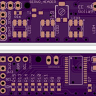
The PCB schematic and layout were designed using Eagle. Most of the ICs were ordered through Digi-Key. They are all surface mount components. Upon arrival of the PCB and the ICs, the components were tested to make sure there were no shorts or burnt components. Manufacturing solder the board by hand the first version of our PCB, but voltage outputs from the buck converter were not right. Chances are the board got burnt or one of the pins of the IC3 was not solder properly.

As a solution, Electronics and Control purchased a stencil, and the second version of the PCB worked perfectly. However, there was one feature that could not be implemented; the kill-switch. The incident is explained fully in the corresponding blog post, but the safety feature was removed from the system.

Conclusion:

(Custom PCB) Showing all SMD components

On the Custom PCB are 2 Surface mount IC’s the Linear Technelogie LT3971-5 Buck Converter

(Showing the package of the Buck Converter)

as well as the Allegro A4988 stepper motor driver. The Buck is a DFN-10 Package. The motor driver is a QFN-28 package.


Both packages are a challenge to solder due to their small size.

The resistors and capacitors are all 0603. The Diode (DO-214AC) and the Inductor (1812) are bigger due to their availability.

Even the LDO is a Surface Mount Device. But this component is no challenge due to it’s big size (TO-263).

The connectors were implemented as PTH (Through hole) components.

The traces were all manually routed following this instructions[3]

Afterwards the PCB was checked using a whole suit of DRC including OSH, Sparkfun and LeanPCB. The PCB passes every single one. Therefore the PCB passes this Analysis.

References

[1]http://web.csulb.edu/~hill/ee400d/Lectures/Week%2009%20Design%20Verification%20and%20Validation/a_Meeting%209%20Agenda%20F’16.pdf

[2]http://web.csulb.edu/~hill/ee400d/Lectures/Week%2009%20Design%20Verification%20and%20Validation/a_Meeting%209%20Agenda%20F’16.pdf

[3] http://arxterra.com/printed-circuit-board-pcb-how-to-layout/

MyoWare – MYOELECTRIC SENSOR

Written by: Carolina Barrera

Our muscles are controlled, and usually move thanks to electric impulses that produce contraction in these, and the reaction to that contraction is what we know as a movement. Electromyography technology was developed to evaluate and record this electrical activity.

Myoelectric signals are becoming popular in medicine and prosthetic technology probably because they are the most recent, and more practical control for people that are missing a limb. The great thing about this idea is that people left with the remaining of their limb can control the device. In other words, the technology is minimizing the difference of what could be consider a full-functional amputee and a full-functional non-amputee.

For our project, we are implementing an EMG sensor which sends an analog signal our MCU. A threshold voltage was set so when the voltage generated by the bicep goes over this value for a certain amount of time the motor is activated.  Since we need to move the arm up and down intervals were assigned. The longer interval will make the arm move down, and the short interval will make it move up.

To test the feasibility of implementing this type of control for our project we needed to see the different values the sensor outputs in the different patterns of motion in the arm (bicep and forearm).

We were not sure if flexing or tensioning the arm were more effective for achieving our threshold, and we wanted to make sure that one wouldn’t interrupt the movement of the other unintended. Our test shows the output of the sensor in four different patterns of moving and tensioning the bicep.

Luis wore the EMG sensor, and we use the built-in Serial sample from the Arduino IDE to read the analog values from the EMG.

We performed different motions with the arm to see which could get a stable high-signal for long enough, and also that I couldn’t be interrupted easily by other unintentional movements when lifting the arm.


Figure 1 shows four different actions that show significantly different outputs that could be implemented in the code when programming the sensor. The four action in chronological order are: relaxed arm, tensioned arm, lifted arm, and tensioned and lifted arm.

From the test, we concluded that tensioning and lifting the arm outputs a relatively large signal (compared to the other motions), and the signal is stable as long as we can keep the arm lifted and tensioned. Later on we discovered that twisting the arm also helps outputs a high signal, so in case up-and-down-movement is restricted we can always try twisting the arm.

We also discovered that the best location to position the sensor (with the electrodes) in the inner side of the bicep -by the side of the arm tha touches the torso. Figure 2 shows the position we put the sensor in the arm. As for the two electrodes, Sparkfun reccommends to place the sensor so one of the electrodes

Interface Integration Piece

Blog Post – Integration Interface

Written by: Carolina Barrera


As mentioned multiple times in our documents, we scheduled integration for the arm for November 19th. No physical integration happened on this day. We didn’t assemble the two systems together, however we made some advancements in the process of integrating the components together.

An idea the two groups wanted to achieved initially, in which our system has a uniform forearm connected the bicep to the hand, and helps harmonize the appearance of the overall system was very desired. It seemed more promising for obtaining a better result in the validation for both teams, and it could lessen the weight that extra pieces (in the integration) add to the system.

Based on this approach, there were a couple of ideas that were considered before bringing up this idea:

  1. The dimensions for the wrist height and width are 3 in. by 3 in, respectively. Adding a cover would mean that our wrist would have a dimension of 3.5 inches at least.
  2. The weight of connector parts, and big screws in-between subsystems would be minimized if we tried.
  3. A harmonized structure would give more opportunities to both groups to increase points in their validation grade.

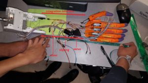
In November 19th, the idea of a one-solid piece helping as a shell mechanism, and unedifying both the forearm and the arm was brought up to consideration. The ideas described above served as reasons for implementing this instead of having the two independent components, as agreed originally. We measured the parts that we have at the moment, and figure the rough length of this new piece. Figure 1 is a picture we took on that day that could help as reference of the dimensions of this new part, and the functionality it would have.

Figure 1 - Agreement Guideline Created on Nov. 19

Figure 1 – Agreement Guideline Created on Nov. 19

To achieve this, the department of design offered their help, and the Junior TA, Van Lieu shepherd both Manufacturing Engineers in finding an aesthetic way to integrate their pieces. The resulting design is shown in figure 2.


In regards to the agreement, there are items that were communicated as clarifications:

  1. The hand and the arm agreed in the idea of implementing a solid interface for integration. This “integration part” that serves as a shell is result of the design and manufacturing efforts of both Manufacturing Engineers, Forrest Pino and Wilson Mach under guidance of Van Lieu, Industrial Design student from CSULB.
  2. This part will house the motor for the hand that allows the wrist rotation on the hand side. Additionally, it will house the wires going to the PCB of the hand -located near to the “elbow”, and a slipring -that will prevent over-twisting and ripping of the wires when the wrist rotates.

We moved forward in the process of integration -even though we were not physically putting together the components. This meeting could be considered the initial phase of the integration, in which the baseline is set, and both groups agreed in dimensions, and restrictions that will direct our project into mission success. More updates will be posted if relevant changes come up in the project. However, with the time left, and the advance stage of both projects don’t give space to last-minute changes.


Experiment: LiDAR Lite

By Jose Alcantar, Electronics and Controls Engineer

Introduction

The LIDAR is a laser range finder which can measure distances of up to 40 meters with an accuracy of ­­±2.5 cm. The device can be used via I2C interface or through pulse width modulation. The LIDAR is to be implemented onto the pathfinder for the use of obstacle detection and avoidance requirement.

Wiring Diagram:


picture6

For testing purposes the LIDAR was wired as shown by the wiring diagram. An Arduino Uno was used using the SCL and SDA I2C pins.

Purpose:

The purpose of this experiment is to calculate and test the field of view of the LIDAR sensor and to test sunlight interference.

Procedure:

An object was placed 0.5 meters away and directly in front of the sensor. The center point of the object was marked and moved in increments of about 0.5 cm to the left until the sensor no longer detected the object. This point was marked and the object was once again replaced to the center and moved in increments of 0.5 cm to the right of the sensor. When the sensor no longer detected the object, the position was marked. The beam diameter was calculated based on the distance between the two points. Using the same method, the experiment was repeated at 1 meter then 1.5 meters.

The LIDAR was tested outside in sunlit conditions to observe the interference of sunlight on the sensor. The sensor was pointed at various objects and the data was observed for any interference.

Results:

The beam diameter was calculated for each of the test runs. At 0.5 meters, the diameter of the beam was well within the mm range. At this distance, the diameter of the beam was about 15 mm. At 1 meter, the calculated beam diameter was about 16 mm. At 1.5 meters, the diameter of the beam was about 2 cm.

Using the LIDAR outside showed no obvious interference. Although, pointing the sensor at different objects with various reflectivity did have some effect on the data. The sensor did have less accurate results on objects with more reflective surfaces.

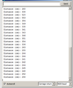
The following table is an example of the output from the serial port on Arduino IDE.

picture7

Heading and GPS Coordinates Formatting

By Jose Alcantar, E&C Engineer

picture4Introduction:

The GPS information received through the Arxterra control panel can be sent through three different data types. The first data type is a 32-bit floating point, the second is a 64-bit floating point or “double” and lastly a 32-bit integer or “long”. Depending on how the settings are configured through the “Robot Capabilities Configuration” menu in the app, the user can choose between any of these three data types. For further information on the data types see the blogpost by Jeff Gomes,

https://www.arxterra.com/arxterra-now-supports-waypoint-navigation/

For our purpose, the 32-bit integer was selected as the data type due to some formatting issues when using the 32-bit floating or 64-bit floating types.

To begin with formatting the coordinates, it must first be understood what values are being sent through the Arxterra app. From the link above, Gomes explains that for the 32-bit integer the units are set to decimicrodegrees. This means that for example, coordinates 33.794904, -117.913712 would be encoded as 33794904, -117913712. The app sends the coordinate values through a 16-byte packet, in which the first 4 bytes are the latitude and the last 4 bytes are the longitude coordinates, bytes being represented in hexadecimal.

picture3

There are different commands available related to GPS navigation, further described in this link,

https://www.arxterra.com/pathfinder-arxterra-communication-commands/

Example:

The following firmware code is based on the WAYPOINT _COORD command, which is used to receive the waypoint coordinate packet data and to format the coordinates into usable values.

After a waypoint is created, for example, 33.794904, -117.124567, the app converts these values into decimicrodegrees and sends the values to the MCU as a 32-bit long. The data being sent will be as follows

{A5, 10 (packetlength),14 (command id), 02 03 AB 58 F9 04 D6 80, (checksum)};

picture4

To extract the data through the Arduino some variables must first be declared:

long waypointLat4;

long waypointLat3;

long waypointLat2;

long waypointLat1;

unsigned long waypointLat;


long waypointLon4;

long waypointLon3;

long waypointLon2;

long waypointLon1;

unsigned long waypointLon;


The byte vales are extracted from the packet and the bits are shifted to be stored into a 32-bit unsigned long.

void waypoint_coordHandler (uint8_t cmd, uint8_t param[], uint8_t n)

{

waypointLat4 = param[0];

waypointLat3 = param[1];

waypointLat2 = param[2];

waypointLat1 = param[3];

waypointLat = (waypointLat4 << 24 | waypointLat3 << 16| waypointLat2 << 8| waypointLat1);


waypointLon4 = param[4];

waypointLon3 = param[5];

waypointLon2 = param[6];

waypointLon1 = param[7];

waypointLon = (waypointLon4 << 24 | waypointLon3 << 16| waypointLon2 <<                  8| waypointLon1);

waypointLon = ~waypointLon;

waypointLon = (waypointLon + 1) * -1;

}

The longitude coordinates require a secondary step to get the right value. Because longitude is a negative value, a 2’s complement operation must be done on the final value to get the right coordinate. Using this formatting, successfully converts the packet data being sent into usable coordinates needed for GPS navigation.

Conclusion:

Following this method, the GPS data sent through the Arxterra control panel can be converted into usable values, which will help with autonomous navigation.

Resources:

https://www.arduino.cc/en/Reference/Bitshift

https://www.arduino.cc/en/Reference/UnsignedLong

https://www.arduino.cc/en/Reference/Long

https://en.wikipedia.org/wiki/Two’s_complement


Implementing MOVE Command Firmware

By Jose Alcantar, Electronics and Controls Engineer

Introduction:

The pathfinder is controlled using the direction pad on both the control panel and through RC mode on the Arxterra app. When using the D-pad, the MOVE command is called from the 3Dotlibrary which is used to control the movement of the motors. Through the design of the 3Dotlibrary, pins 5,6,10 and 13 on the Arduino Leonardo are tied to the MOVE command. Because of how are system is designed, firmware was written to take advantage of the data from the D-pad and MOVE command, without using the dedicated pins.

When a button is pressed on the D-pad a packet is sent through Bluetooth and is decoded by the Arduino. The packet data is sent in the following format:

{A5,  (packetlength), 01 (command id), 01 80 01 80, (checksum)};

The first value after the command id specifies the direction for the left set of wheels on the pathfinder followed by the second byte which is the PWM value to control the speed of those motors. The last next two bytes are used to control the right set of motors.

The following is a brief description of how the index values are interpreted


/***********************************

* motion command = 0x01

* motordata[3]   left run    (FORWARD = index 1, BACKWARD = index 2,

BRAKE =   index 3, RELEASE = index 4)

* motordata[4]   left speed  0 – 255

* motordata[5]   right run   (FORWARD, BACKWARD, BRAKE, RELEASE)

* motordata[6]   right speed 0 – 255

* example

* forward half speed  0x01, 0x01, 0x80, 0x01, 0x80 0101800180

***********************************/


Firmware:

Understanding the data being sent from the D-pad, firmware was written for the motor controls. A series of if-else statements were used to account for the different data packets that the Arxterra app transmits:


void moveHandler (uint8_t cmd, uint8_t param[], uint8_t n)

{

Serial.write(cmd);             // move command = 0x01

Serial.write(n);               // number of param = 4

for (int i=0;i<n;i++)          // param = 01 80 01 80

{

Serial.write (param[i]);

}


if(param[0] == 1 && param[2] == 1)

{

input_pwm1 = param[1];

input_pwm2 = param[3];

left_forward();

right_forward();


}

else if( param[0] == 2 && param[2] == 2)

{

input_pwm1 = param[1];

input_pwm2 = param[3];

left_reverse();

right_reverse();

}

else if( param[0] == 1 && param[2] == 2)

{

input_pwm1 = param[1];

input_pwm2 = param[3];

right_turn();

}

else if(param[0] == 2 && param[2] == 1)

{

input_pwm1 = param[1];

input_pwm2 = param[3];

left_turn();

}

else if( param[0] == 1 && param[2] == 4)

{

input_pwm1 = param[1];

input_pwm2 = param[3];

left_forward();

right_release();

}

else if(param[0] == 2 && param[2] == 4)

{

input_pwm1 = param[1];

input_pwm2 = param[3];

left_forward();

right_release();

}

else if(param[0] == 4 && param[2] == 1)

{

input_pwm1 = param[1];

input_pwm2 = param[3];

left_release();

right_forward();

}

else if(param[0] == 4 && param[2] == 2)

{

input_pwm1 = param[1];

input_pwm2 = param[3];

left_release();

right_reverse();

}

else if(param[0] == 4 && param[2] == 4)

{

input_pwm1 = param[1];

input_pwm2 = param[3];

left_release();

right_release();

}


Conclusion:

Following this code format, the motors can be controlled to move forward, reverse, brake, and release. Depending on the values being transmitted, the functions to drive the motors are called. The PWM values are then extracted from the packet and stored onto a variable to control the speed.

Motor Control Interface

By Jose Alcantar, Electronics and Controls Engineer

Introduction:

To drive the six motors independently as per requirement, 3 dual motor drivers are being utilized. Three VNH5019 motor drivers will be used to control each motor along with a PCA96805 I/O expander and a hex inverter.

VNH5019:

The VNH5019 dual motor driver requires three pins to control each of the two H-Bridges integrated onto the board. The two-motor direction pins (M1INA and M1INB) for the first H-Bridge use a digital output high and low to set the direction of the motor. The following truth table summarizes the different settings for the pins:

picture2

For example, to drive the motor clockwise M1INA is set high, while M1INB is set low. To reverse the direction M1INA is set low and M1INB is set high.

The third pin (M1PWM) is used to control the speed of the motor via a PWM signal.

The pathfinder will utilize three VNH5019 dual motor driver boards, with each board requiring 6 pins to control each motor. This gives us a total of 18 pins needed to control the motors. Due to the limitation of pins on the Arduino Leonardo, a PCA9685 16-channel 12-bit I/O expander along with a hex inverter will be used to control each of these pins.

PCA9685 & 74HC04 Hex Inverter:

The PCA9685 I/O expander allows the user to expand the capabilities of the Arduino by providing an additional 16 channels through I2C interface. Six of these channels will be dedicated for controlling the PWM input of all six H-Bridges. The PCA9685 has a dedicated library available that simplifies the use of the board. The following sample code shows how to set the output of one of these channels.

pwm.setPWM(0, 0, 4095);   //Sets the output to 100% duty cycle

In the above sample code the first input is the channel output pin, followed by the off time for the duty cycle and finally, the last value is the on-time for the duty cycle. Because the board has 12-bit resolution, the values for the duty cycle range between (0 – 4095), giving 4096 steps.

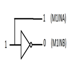
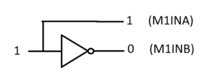
To control the motor direction, the use of a Hex inverter along with the I/O expander will be used to reduce the number of pins being utilized. Using an inverter, the motor direction can be controlled clockwise and counterclockwise with the use of a single pin. The following diagram shows the basic idea of how the direction will be determined.

picture1

In this case, setting the channel output HIGH or 100% duty cycle on the I/O expander, will set the direction pin M1INA high and M1INB low, driving the motor in the clockwise direction. Setting the channel output LOW, or 0% duty cycle, will do the opposite.

Conclusion:

With this configuration, the 18 pins needed to drive the motors is reduced to only 12 pins from the I/O expander. This leaves four more pins on the expander to drive servos or other actuators.