By: Alan Valles (Electronics and Control)
Approved by: Ijya Karki (Project Manager)
Table of Contents
The Purpose of this experiment is to measure the stall current of the Pololu 1117 motor. This will be done in order to compare it to its rated value of 800mA.
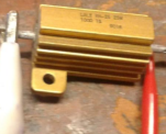
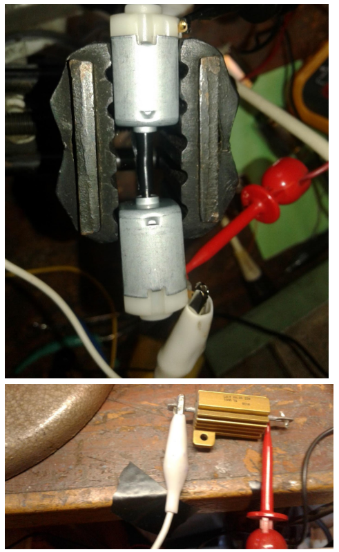
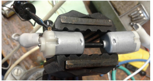
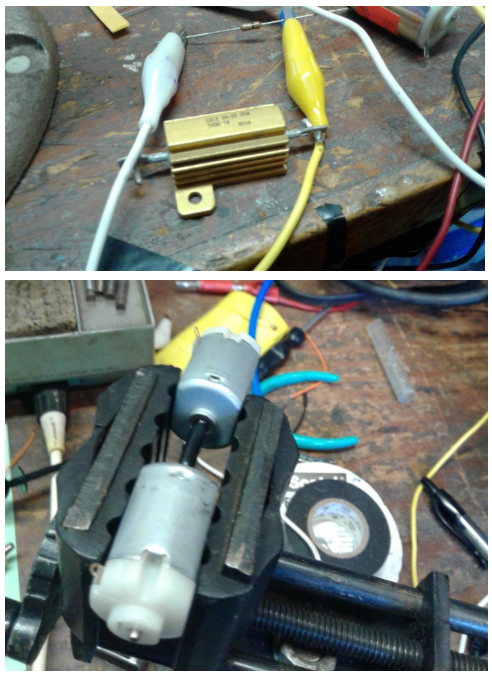
A stall current experiment was performed in order to see the actual stall current produced by Pololu 1117, this was done at the recommendation of Project Manager and ENC Division manager. Stall Current was measured utilizing two Pololu 1117 130 motors. The motors were set up in a mini vise as shown. Two small electrical loads were applied, one 100Ohm and One 1Ohm. The currents into the driving motor and out of the receiving motor were measured. As discussed in ENC meeting this should give us our stall current. The stall Current for the Pololu 1117 is rated at 800mA on the Pololu website.
The first run of test result in really low output currents to the motor load. However, this was due to the shafts losing grip of each other because the electrical tape overheated and began to lose grip of the two shafts. Thus, the receiving motor did not spin at a strong frequency with the other motor. The tape was redone and the experiment current increased by about 60%. Thus, the measured stall current would be around 492 mA. However, the measured current from inside a Tamiya gearbox was about 500mA so this value does not make sense. However, if another device could be used to tightly grip both motor shafts in order to better sync their frequencies than the number may have been closer to the rated 800mA. However, the rated 800mA was for 6v DC but the motor will be operating at 5V DC. As shown in the experiment. Taking the maximum motor value of 335 and multiplying by two we get, 670mA. This value is less than the rated 800mA rated stall current. One can figure that the actual stall current will be under the rated 800mA
| Electrical Load | Driving Motor Current | Load Motor Current |
| 100Ohm | 321 | 50 |
| 1Ohm | 335 | 100 |
| 1Ohm Redo | 328 | 164 |
In conclusion an experiment was done to measure the stall current of the Pololu 1117. The results were not definitive. However, using worst case analysis, the stall current of the Pololu 1117 motor can be seen as less than the 6v rating of 800mA since we will be operating at 5v.
[1] http://arxterra.com/pathfinder-motor-stall-current-test/

Table of Contents
By: Ijya Karki (Project Manager)
Project Manager Roles include certain tasks that must be completed, example:
There is a split of skills that a good project manager must possess, looking at the above list these skills can be differentiated with the words creating and managing. The easier of the two tasks include the creating. Documentation and guidance from the company CEO and President make creating a do-able process. The harder of the two skill sets is the managing portion.
What makes managing difficult? Managing can be difficult when one is working with their class mates and friends. There has to be a degree of authority established in the group so that there is an understanding that the Project Manager has the final says. This can become difficult when managing friends that one has spent years in class with.
From my communications class, I learned that these are typical issues that can arise when leading a group:
No one has perfecting good managing skills but these are suggestions and insights that can help one take a better approach than the mistakes listed above. Being PM doesn’t mean there is a choice that has to be made between friendship or PM roles. One can keep both tittles if they approach their responsibilities correctly.
In the event that a member in your group lacks passion, it is important to recognize these members from the start. The best solution can be to communicate with the member and figure out the reasoning behind why they are not committed and trying your best to motivate them. If that fails then you can converse with the Division manager to try and change or find a solution to the problem. Maybe your teammate wants to be in another group or there is a well skilled individual in another group that can help your teammate out. If all else fails, then communicate to the instructor the issue and the solutions you have already tried. Do not prolong this process, the further into the semester you go the more it will affect your grade if a teammate is unresponsive, uninterested, and idle. Be aware that if one of your teammates drop the course then you are responsible to complete both PM duties and the duties of the member that dropped.
In the event that a member in your group lacks skill, it is important to get them the help they need early on. Take initiative and talk to their division manager with a request that they spend more time on the material with your teammate or ask for a well skilled individual to be paired up to aid your teammate in their process. You want to avoid completing their tasks for them. If you get in the habit of finishing all of your teammate’s tasks, then you will have double the load and an idle member. The primary solution a skill lacking member should not be you taking over their job, but rather you directing them to their division manager for help.
| THE DOS | THE DONTS |
| Remain honest about grading | Don’t take out anger with grades |
| Assign assignments at least a week in advance | Don’t assign last minute assignments (unless an emergency occurs with the project) |
| Sit down with members and understand why they are struggling/figure out ways you can help them or direct them to the right person that can help | Don’t single out members and blame them |
| Assign members tasks and follow up on them | Don’t assume that members know what must be done and just wait for them to tell you what they completed |
| Keep grading scale fair by giving points to various parts of the project | Don’t be lenient with deadlines |

By Jose Rodriguez (Electronics & Control)
Approved By Inna Echual (Project Manager)
Objective: Because of our current design, a port expander is needed because there are no more available pins on our Arduino to read data from the reed switches. The reed switches will be used to halt the panels from cocooning more than it needs to; if it goes past a certain angle, it could hit the adjacent panel and damage its cells.
The Microchip MCP23017 is a 16-bit serial expander with I2C serial interface. This 28-pin IC offers sixteen inputs or outputs. Figure 1 shows the pinout data sheet for the IC:

Figure 1: MCP23017 Pinout [1]
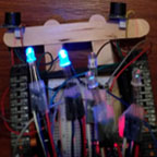
Firstly, the expander was checked to see if it worked using two LEDs, which will be set high and low using the IC. Note that there are two banks, A and B, and each bank has a total of 8 pins. Both banks will be used in this blog to understand either or both of their activations.
The code in Figure 2 is used to set up ports as outputs. The address for the device can be found on the data sheet [2], but to save time it is x20. To set pins as input, a one need to be set on the fourth column of the code depending on the required pin. Hex values are used, so for example, FF will set all pins as inputs. F0 sets the first 4 pins as inputs and the last 4 pins as outputs.
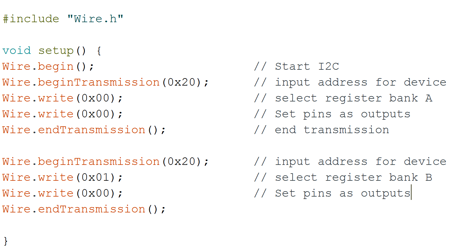
Figure 2: Code to Set Up Input and Output Ports
Once setup is complete, it becomes simple to set ports as high or low. The code in Figure 3 shows how to set up the pins using binary values. Four lines of code are needed to write on pins. The code takes a lot of space but there is a library that has been made for the MCP23017 by Adafruit that adds 1,000 bytes of memory.
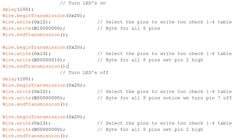
Figure 3: Code to Set up Pins
The Adafruit library needs to be downloaded and saved in the Arduino library because it can be used with the IC. The code for using the library is shown in Figure 4. First the Adafruit library has to be included by writing #include. The code from Adafruit is similar to that of the Arduino when it comes to setting up pins, but mcp. needs to be added before pinMode. The setup is straight forward however note that Bank b refers to pins 8 to 15.
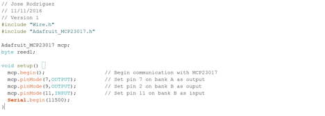
Figure 4: Code to Use Adafruit Library
Alternatively, the following code in Figure 5 turns two led on and off, but is more efficient as it requires less code. Either method can be used but the latter is cleaner than the other. If memory code is an issue, then the longer method (firts code) will be optimal to save memory.
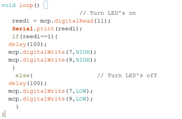
Figure 5: Alternative Code to Light LEDs
Adding a port expander is not as hard as one will think as using the Adafruit library makes the process even easier. To read a pin the command that will be needed is mcp.digitalRead only. The second method makes the code cleaner, but the first method gives an individual an idea of what is going on behind the second method.
[1] Maximising your Arduino’s I/O ports with MCP23017: http://tronixstuff.com/2011/08/26/tutorial-maximising-your-arduinos-io-ports/
[2] MCP23017 Data Sheet: http://ww1.microchip.com/downloads/en/DeviceDoc/21952b.pdf

By Ridwan Maassarani (Design & Manufacturing)
Edited and Approved By Inna Echual (Project Manager)
Objective: The thickness of our panels must be carefully chosen as “too large” of a thickness could result in additional weight, possibly causing unnecessary strain and bending. Though the chassis could withstand our panels weight a maximum 50 lbs (as stated by the chassis group), we would like to chose a weight that would minimize bending as bending could cause our solar cells to break due to their delicate state.
The thickness of the panels should be chosen so that it can carry its own weight under the force of gravity, as well as be well below the maximum 50 lbs. load requirement set by the chassis group. Cutting various panel configuration numerous times using varying aluminum thicknesses would take a long time and waste expensive material, the stress analysis tool feature in SolidWorks was used.

Figure 1: Panel Reference
The panel being evaluated is the butt panel (see Figure 1). The stress analysis tool was used on the butt panel to verify that it wouldn’t bend under the force of gravity.
The first step is to define a location where the object being tested will not move. In my case, it is three mounting holes for the hinge. Gravity acting on the top of the back panel was defined as the load. Using the mass properties tool under evaluate in SolidWorks, the approximate mass of the back panel was obtained to be 383.93 grams.
Note that the additional of the cells, rubber sheets, and glass will increase the weight; to remedy this, the weight of a single cell was measured and multiplied with the amount of cells that can fit onto the back panel.

Figure 2: Solar Cell Arrangement on Butt Panel
Currently, 33 cells can fit on the butt panel comfortably with 2mm spacing between them (also taking into account panel cutouts for the gears, see Figure 2 above). The weight of one cell was measured to be 0.75 grams so an approximate addition of 24.75 grams is added due to cells. Masses pertaining to the solder and copper tape is negligible but the cell system was rounded to 30 grams.
The total mass was converted to Newtons, which was entered into one of the SimulationXpress analysis wizard. Since aluminum was determined to be the material of our panels, it was selected in the design.
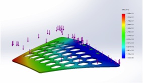
Figure 3: Butt Panel Displacement using 3.175mm Aluminum
Figure 3 shows the displacement acting on the panel. An eDrawing file can be saved once the results have been calculated. Furthermore, the tool can be used to optimize the design. For example, it allows the user to change dimension right and set goals to meet the customer’s needs. SolidWorks will calculate multiple scenarios to meet specific goals.

Table 1: Base to Butt Panel Deflection Data

Graph 1: Thickness (mm) vs. Deflection (mm) of Butt Panel
Data concerning deflection was generated and inputted on Excel in order to determine panel thickness unacceptable deflection is seen. Table 1 shows the deflection from the base panel to the butt panel. The relationship between the varying thicknesses and resulting deflection is shown in Graph 1. The x-axis shows different thicknesses of 6061-T6 aluminum in millimeters and the y-axis represents the deflection distance in millimeters.
The four side panels (left front, left back, right front, right back) are similar in size and weight so the same stress analysis was done on the deflection between the base panel and the right front panel. Figure 4 shows the displacement acting on the aforementioned panel.
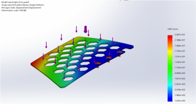
Figure 4: Right Front Panel Displacement using 3.175mm Aluminum
Figure 4 shows the deflection between the base and right front panel. Table 2 and Graph 2 contain the data on the relationship between thickness and deflection distance, as done with the butt panel.
Based on the data, we were able to determine that 1.25 in (3.175 mm) is the optimal thickness our aluminum should be to minimize bending. Our motors will be able to handle this weight and the total weight (including the addition of cells, wires, glass, motors, etc.) is still under the weight restriction of 50 lbs as set by the chassis group.

Table of Contents
By: Ijya Karki (Project Manager)
As the semester comes to an end, it gets closer to testing the actual product. This is where the profile objective and the mission profile from the CDR is brought to life. The game, Save the Human, is played by four teams (Wednesday Velociraptpr, Thursday Velociraptor, Biped, and Goliath). The Game committee met on December 3rd, 2016 to finalize the game rules. Then, Ijya Karki, Fabian Suske, and Kristen Oduca built the arena pieces.
The project objective is to design a 6th generation toy Biped robot that will statically walk using two feet with the goal of dynamic walking.
The Biped will utilize the 3Dot Board
The Biped will partake in an end of semester game: Save The Human
The project must be completed by December 14th, 2016
The budget must stay under $125.00
Biped shall compete, alongside other toys such as Goliath and Velociraptors, in an end of semester approximately hour long game: Save the Human. Biped should successfully walk, using Goliath’s live video feed as the field of view, from the opposite end of the room to the finish area without coming into contact with a Velociraptor. The Biped will maneuver through multiple obstacles by turning through walls, sensing color pads, balancing on six degrees inclines/declines, and stepping through uneven terrain placed on top of Linoleum floors.
The First Step to building the game arena was to modify and finalize the rules that were proposed at the beginning of the semester. The original rules can be found under the Thursday Velociraptor blog posts: http://arxterra.com/fall-2016-game-save-the-human/
Suggested changes made:
Determining the sizes of various cardboard pieces.
To fulfill that the game would consist of at least 20 percent cardboard, we had to create a total of eleven 1 ft by 1 ft cardboard uneven pieces and two 3ft x 1 ft hills.
Arena size 12 ft x 5 ft –> 12 * 5 = 60 ft
60*20%= 12 ft (thus the game must have 12 ft of cardboard to satisfy 20%)
Total cardboard pieces are:
Thus with 17 ft of cardboard used, the game committee successfully satisfied having building 20 % (12 ft) of the Arena with Cardboard.

Purchasing the necessary parts
Cardboard, hot glue, and glue gun was purchased at home depot.
Using box cutters, scissors and parts purchased at home depot, Ijya Karki, Kristen Oduca, and Fabian Suske build the necessary pieces to fill the arena.


By: Taylor Farr (E&C)
Approved by Ryan Daly (Division Manager for Electronics and Controls)
Lam Nguyen (Project Manager)
Table of Contents
In order to fulfill these requirements, a software algorithm needs to be implemented that reads the rotary sensors and move the dc motors and servos such that it is able to walk. Since the Velociraptor is using dc motors for the legs, rotary encoders need to be utilized so that the system knows the rpm and position of the motors at all times. No two dc motors are the same, so the pwm signal sent to the motors will vary for each otherwise the robot will be unable to walk. For our final design, we intend to use potentiometers for our rotary sensors.
For our CDR demonstration, we intended to use the potentiometers, however, this proved to be difficult to implement due to the size. Instead, we used optical sensors. The optical sensors behave like a switch. An led emits light while a BJT senses light. We then incorporated two circles with black ink across the diameter.
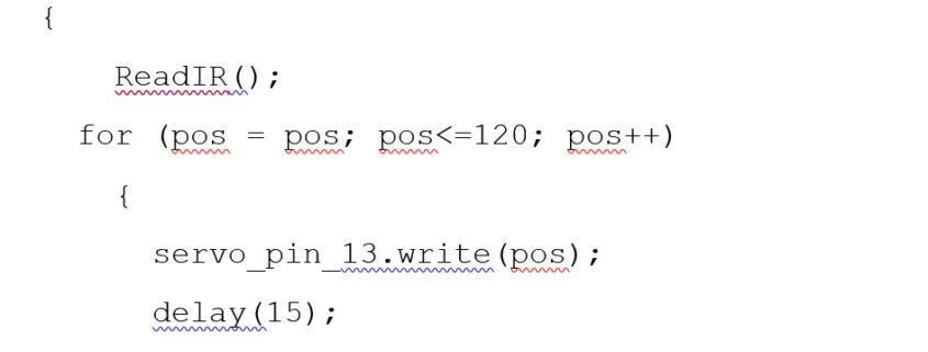
The algorithm is simple:
The algorithm uses a for loop to gradually move the servo to the desired position. Following that is a while loop. In the while loop, both motors move forward until the optoreflective switch reads a 0 output (An output of 1 indicates that the switch is looking at a white surface, and an output of 0 indicates the black line). There are two switches that need to be read, so some if statements are necessary in case one motor has moved 180 degrees before the other motor. After each sensor reads 0, each motor will stop. This will then use the for loop again to move the servo in the opposite direction. This subroutine is under moveHandler so that the systems engineer can use their Arxterra app to call the function using Bluetooth.
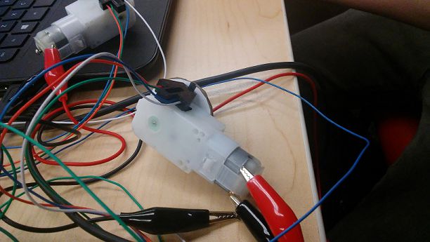
Figure 1 – Dc Motor with Optical Encoders
void moveHandler (uint8_t cmd, uint8_t param[], uint8_t n)
{
ReadIR();
for (pos = pos; pos<=120; pos++)
{
servo_pin_13.write(pos);
delay(15);
SoftwareServo::refresh();
}
ReadIR();
motorA.go(param[0],0x40);// go(direction,pwm) –> direction: FORWARD =1, BACKWARD =2, BRAKE = 3, RELEASE = 4; pwm range(0-255) used to control the speed of the motor
//in my case I used 1 to move forward and a 255 for max speed
motorB.go(param[2],0x40);// go(direction,pwm) –> direction: FORWARD =1, BACKWARD =2, BRAKE = 3, RELEASE = 4; pwm range(0-255) used to control the speed of the motor
delay(500); // need to calculate delay
ReadIR();
// IR = digitalRead(sig);
//Serial.println(IR);
// IR2 = digitalRead(sig2);
while ((IR!=0)&&(IR2!=0))
{
motorA.go(param[0],0x40);// go(direction,pwm) –> direction: FORWARD =1, BACKWARD =2, BRAKE = 3, RELEASE = 4; pwm range(0-255) used to control the speed of the motor
//in my case I used 1 to move forward and a 255 for max speed
// IR = digitalRead(sig);
ReadIR();
motorB.go(param[2],0x40);// go(direction,pwm) –> direction: FORWARD =1, BACKWARD =2, BRAKE = 3, RELEASE = 4; pwm range(0-255) used to control the speed of the motor
// IR2 = digitalRead(sig2);
ReadIR();
}
if ((IR==0)&&(IR2!=0))
{
motorA.brake();
ReadIR();
while (IR2!=0)
{
motorB.go(param[2],0x40);// go(direction,pwm) –> direction: FORWARD =1, BACKWARD =2, BRAKE = 3, RELEASE = 4; pwm range(0-255) used to control the speed of the motor
// IR2 = digitalRead(sig2);
ReadIR();
}
if (IR2==0)
{
motorB.brake();
ReadIR();
}
}
if ((IR!=0)&&(IR2==0))
{
motorB.brake();
ReadIR();
while (IR!=0)
{
motorA.go(param[0],0x40);// go(direction,pwm) –> direction: FORWARD =1, BACKWARD =2, BRAKE = 3, RELEASE = 4; pwm range(0-255) used to control the speed of the motor
// IR = digitalRead(sig);
ReadIR();
}
if (IR==0)
{
motorA.brake();
ReadIR();
}
}
//IR = digitalRead(sig);
//IR2 = digitalRead(sig2);
ReadIR();
for (pos=pos; pos>=60; pos–)
{
servo_pin_13.write(pos);
delay(15);
SoftwareServo::refresh();
}
motorA.go(param[0],0x40);// go(direction,pwm) –> direction: FORWARD =1, BACKWARD =2, BRAKE = 3, RELEASE = 4; pwm range(0-255) used to control the speed of the motor
//in my case I used 1 to move forward and a 255 for max speed
motorB.go(param[2],0x40);// go(direction,pwm) –> direction: FORWARD =1, BACKWARD =2, BRAKE = 3, RELEASE = 4; pwm range(0-255) used to control the speed of the motor
delay(500); // need to calculate delay
// IR = digitalRead(sig);
// Serial.println(IR);
// IR2 = digitalRead(sig2);
ReadIR();
while ((IR!=0)&&(IR2!=0))
{
motorA.go(param[0],0x40);// go(direction,pwm) –> direction: FORWARD =1, BACKWARD =2, BRAKE = 3, RELEASE = 4; pwm range(0-255) used to control the speed of the motor
//in my case I used 1 to move forward and a 255 for max speed
// IR = digitalRead(sig);
ReadIR();
motorB.go(param[2],0x40);// go(direction,pwm) –> direction: FORWARD =1, BACKWARD =2, BRAKE = 3, RELEASE = 4; pwm range(0-255) used to control the speed of the motor
// IR2 = digitalRead(sig2);
ReadIR();
}
ReadIR();
if ((IR==0)&&(IR2!=0))
{
motorA.brake();
ReadIR();
while (IR2!=0)
{
motorB.go(param[2],0x40);// go(direction,pwm) –> direction: FORWARD =1, BACKWARD =2, BRAKE = 3, RELEASE = 4; pwm range(0-255) used to control the speed of the motor
// IR2 = digitalRead(sig2);
ReadIR();
}
if (IR2==0)
{
motorB.brake();
ReadIR();
}
}
if ((IR!=0)&&(IR2==0))
{
motorB.brake();
ReadIR();
while (IR!=0)
{
motorA.go(param[0],0x40);// go(direction,pwm) –> direction: FORWARD =1, BACKWARD =2, BRAKE = 3, RELEASE = 4; pwm range(0-255) used to control the speed of the motor
// IR = digitalRead(sig);
ReadIR();
}
if (IR==0)
{
motorA.brake();
ReadIR();
}
}
} // moveHandler
void ReadIR()
{
// Read in the ADC and convert it to a voltage:
int proximityADC = analogRead(QRD1114_PIN);
int proximityADC2 = analogRead(QRD1114_PIN2);
if (proximityADC < 630){
IR = HIGH;
}
else {
IR = LOW;
}
if (proximityADC2 < 630){
IR2 = HIGH;
}
else {
IR2 = LOW;
}
We were able to get the motors to move successfully. However, problems arose when we connected this to our prototype. There was more friction in the wheels than anticipated. Another issue is making sure that the legs start off in the correct position. If not, it is very likely that the robot will become unstable, and fall over.