

Table of Contents
By: Hector Martinez (Manufacturing)
Approved by: Ijya Karki (Project Manager)
Once the schematic design is complete by E&C engineer, Allen, it is time to design the PCB layout. The PCB layout needs to have a thought out design that will work logically and seamlessly with our project. Since our PCB will be a shield for the 3dot board, we also have to consider the dimensions of the 3dot board as well as space allocation.
There are a lot of resources online that will explain how to layout a pcb, but one crucial bit of advice that I received came from our president Fabian, he suggested I start by grouping all the components that work together.

Fig. 1 – New PCB project based on Schematic layout.
For example, our SX1509 GPIO expander contains a decoupling capacitor at the power input and 3 resistors that will work with our color sensor, by grouping those components together you begin to think about how and where these groups of components will be placed.

Fig. 2 – Grouping of SX1509 and its attributed components.
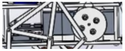
As you continue to group all your components you begin to realize that some groups must be place at specific locations. The picture below shows the connectors for motor1 and motor2 are connected directly to the board at A and B. Additionally, since we will be using an external battery the LM1048IS that we will use to regulate that voltage must be close to the EXT battery connection towards the bottom of the board along with all its components.

Fig. 3 – Continuing to group components you realize where some components must go.
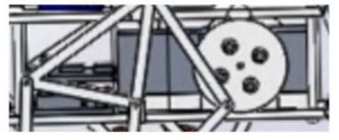
Once you are done grouping, the tedious job laying down traces to connect all your components. You may choose to place some of your smd components on the underside of the board or leave everything on one side. When you begin to trace, you want to try and route all your traces on one side, once you are unable to do this without traces overlapping, you can take advantage of Vias and placing traces on the other side of the board.

Fig. 4 – Grouping complete, time to lay down traces. The blue component is the SX1509 on the underside of the board, this is done when space is limited.
Clearly, we have plenty of space to fit all of our components on one side of the board. Once the traces have been placed you may opt to go through and make all text on the silk screen the same dimensions. This makes your board visually appealing and will help when it is time to solder.

Fig. 5 – You are done!
The image above shows red and blue traces that connect all components together, each is on opposite sides of the board. The planes is red or blue are grounds, these are meant to protect the board from noise, etc. Once you are done, you can admire your work.
[1] PCB layout

By: Hector Martinez (Manufacturing)
Approved by: Ijya Karki (Project Manager)
Table of Contents
The prototype process should be thought out and well planned. There needs to be a plan that includes a parts list, a schematic, tools list and clean workspace. I had none of these. Having been moved from Prosthetic Arm there was a steep learning curve on walking robotics as well as understanding the state and direction of the Biped project as it stood. It was an uphill battle which included two redesigns 2 weeks before CDR. Having done two prototypes there are some things that I realize I could have done differently had I not been under the gun.
Prototyping starts with SolidWorks (or whatever program you’re using) taking into consideration how your project will come together. You have to think about the hardware you are using and think about clearance and tolerances, as well as your materials. For example, while laser cutting the leg linkages for our first prototype for CDR, I didn’t realize the mounting holes for all the linkages were too close to the edges which resulted in broken mounts because these were cut from wood.

Fig. 1 – First prototype laser cuts, notice the mounting holes are really close to the edges

Fig. 2 – Broken linkages due to poor design
While putting together the second prototype for CDR, I decided to use acrylic and use M3 bolts to hold everything together. I didn’t consider the clearance of the bolt head and ended up having issues on several linkages hitting bolt heads due to insufficient clearance.
Another issue I ran into came from not researching the availability of part sizes, I assumed that I would be able to find M3 bolts up to 35mm. These were to be used on the feet to act as ankles and allow weight shifting. The feet were 3D printed and the mounting holes were set to 30mm, I decided to look for the hardware after printing and realized the longest M3 bolts I could get were 30mm.

Fig. 3 – 30mm M3 screw used because 35mm screw was not available
The thing about manufacturing is you have to learn to be creative. Some of the issues explained above had easy fixes, others didn’t, and for some the “fix” made things worse. For clearance issues I used spacers to create the clearance necessary. For the bolts that weren’t long enough I bolted them in such a way that they were still secured. Except for one of these bolts I decided to use superglue which fixed the bolt to the foot (Fig. 3), these were meant to fit loosely to allow for rotation. In this case you need to realize what you did wrong and fine the best solution. In my case the only option was to 3D print that foot again.
Fig. 4 – Spacers and nuts used to lock linkages in place, locking nuts would have been a better alternative
The purpose of prototyping is to discover issues with your design as well as what is missing. For our prototype we wanted to know if our design would statically walk. While testing we discovered that our robot could not stand because the angle of the linkages would not allow it stand. Brandon, our E&C, suggested we make “shoes” to correct this issue. By making shoes we were able to move forward and continue testing our walking motion. While this was a quick fix for CDR, prototyping pointed to a major design flaw that needs to be addressed.

Fig. 5 – Prototype with “shoes” to correct stance, and tape to hold the 3dot board
[1] Solidworks

By: Alan Valles (Electronics and Control)
Approved by: Ijya Karki (Project Manager)
Table of Contents
The purpose of this document is to explain the logical flow of the firmware portion of the Biped. Several external libraries will be used in order to control our electromechanical devices with firmware.
The most recent design iteration of the Biped walking robot calls for a single DC motor, four servos to turn and shift center of mass, and a color sensor to detect power pads which will be on the floor. The single DC motor will provide the electromotive force for two legs which will be out of phase by 180 degrees through a crankshaft. The servos will provide the x and y shifts in the center of mass.
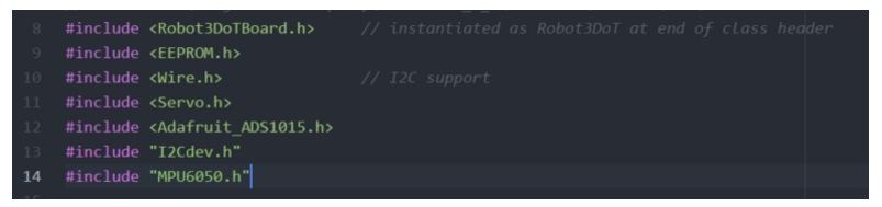
There are several additional libraries that we will be using. The non-default libraries are, Robot3DotBoard, ADS_1015, and I2cDev which includes the MPU6050 files. As a side note, I am using the Arduino IDE with an external text editor for all of the screenshots below.
As the program is running, it will constantly read the rotary position sensor by requesting this information from the ADS1015 which will be connected onto the I2C bus. Thus, depending on the user input into the app which will be in RC mode, it will move the motors to the correct position in order to turn or continuously go straight. Similar to the code snippet below.
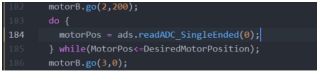
Other control logic will be implemented based on the parameters received from the Move command. Depending on the button pressed in the move command, i.e. straight left,right, or reverse. The desired motor position may be different. For example, when making a left turn, the DesiredMotorPosition will correspond to the value of the left foot planted, the code will then stop the motor. Next, code will be inserted to move to ankle servo to a specified angle, and walking will commence again. This will be repeated but then the servo will move back to the home position.

Some challenges will be the Servos maintaining 0 degrees home position throughout the game. I have noticed that due to the difference in servo control boards, play in gears or other unknown factors, the servo position seems to every so often move to the 0 degree position but with an offset. More detailed code will be uploaded to the Github once it has been found to be bug free.
In conclusion, the electromechanical devices will be controlled utilizing our Firmware design. Several external libraries will be used in order to ensure mission success and maintain a controlled walking and turning motion.
[1] https://github.com/jrowberg/i2cdevlib
[2] https://github.com/adafruit/Adafruit_ADS1X15
[1] Biped Code
By: Alan Valles (Electronics and Control)
Approved by: Ijya Karki (Project Manager)
Table of Contents
The purpose of this document is to define and go through some of the choices and reasons for component selection of the custom 3dot shield. There are a couple main components that were chosen for the shield, the IMU which is the MPU-6050 which is provided by The Robot Company. The SX1509B which is the GPIO expander, ADS1015 the Analog to Digital converter for the rotary position sensor.
First, the IMU chosen was the MPU-6050. The original MPU breakout board was designed by sparkfun and has a retail price of 39.95. However, an imitation board with similar functionality was provided by The Robot Company. Since this was provided at no additional cost to the project, it was selected based on price. A 10-pin .1” pitch socket was provided on the 3dot Shield for the MPU-6050 Breakout Board to connect to. This board also plays nice with the 3dot board since it has a 3.3 v logic level.

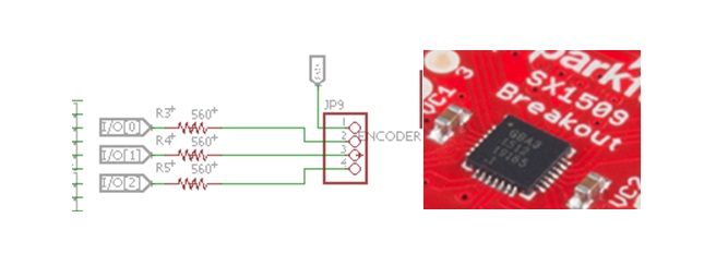
The SX1509B is a low power GPIO expander that was selected for the 3dot board. Since latest revision of the 3dot board does not have any available I/O ports it was decided to use an I2C GPIO expander since the SX1509 has PWM capabilities it may be able to control the signal of a servo. This is needed in order to shift weight between feet in order to produce a walking motion with the robot. The SX1509 also has a sparkfun library which aids in meeting scheduling deadlines of the project. Another small peripheral device was the color pad indicator light. It will connect to an LED on the top of the Robot and when a power pad is walked over, the light will turn on per the game rules. Some SMD resistors were added to the PCB so the final assembly will just house the LED itself. The optimal brightness is around 560 Ohms for the through hole RGB LED that will be used. This bright ness is based on the forward voltage required by the different colored LEDs. Thus, since diodes emitting at different colors, or wavelengths will generally require different current limiting resistors to dictate the brightness. The LEDs need a forward current of about ~160 more or less and thus something close to this value will be used.
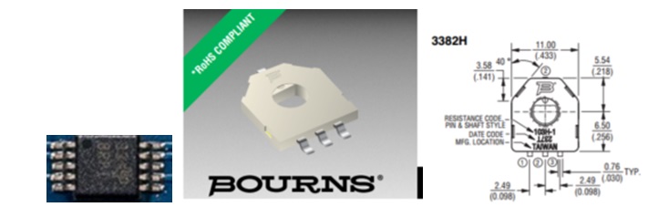
Furthermore, the ADS1015 was selected as the Analog to Digital converter which would be able to read information from our rotary positions sensor. The ADS1015 was selected due to the available documentation, spark fun library, and due to the recommendation of the velociraptor group. This collaborative effort will help drive projects forward by allowing for more code between them. Also, Adafruit provides a library for utilizing this component as well and has some good documentation on their website utilizing this device. The Rotary position sensor used will be of the BOURNS 3382 series. The bourns rotary positions sensor is a potentiometer that can support 360 degree continuous rotation, ideal for the output shaft of the dc motor. The diameter of our shaft is a 3mm hexagonal pattern and should fit into the bourns 4mm rotary position sensor based on the datasheet.
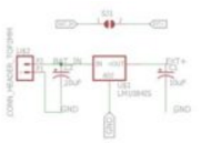
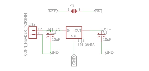
Finally, at the recommendation of our President, I made the decision to connect our entire system to a Linear Dropout regulator which will provide 5V to the servos instead of having them tap directly to the output voltage of the battery. The LM1084IS by Texas Instruments was chosen as the voltage regulator. This was because it provides 5V and up to 5A output. Also due to the availability of a convenient eagle part. The TI LM1084 was configured in a typical application circuit as shown below. A Solder jumper was placed for added flexibility. This solder jumper allows for a different battery voltage to still be applied such as a 3.7v battery and the servo would connect to this unregulated.
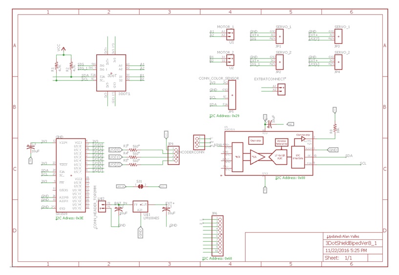
This is our final completed schematic for the 3dot shield. It shows all the components that were listed above. The finalized board layout can also be seen in our Manufacturing Engineers blog post who did a wonderful job. Along with the major components there are also some pullup resistors for the I2C bus which are sized due the length of cable connecting all devices, however 4.7k or 10k are good ‘default’ values if one does not want to go through the process of calculating mutual inductances and capacitances. It is also good practices to put decoupling caps in front of voltage inputs of sensitive components. This will block any noisy High frequency signals from affecting the chip’s performance. There is a handy guide on how to size and select decoupling capacitor values based on Farads, Equivalent Series Resistance in reference [9] but be warned it is not a read for the faint of heart. A github link will be included at a later time, including all of the schematics, and necessary libraries to modify and rebuild this project.
In conclusion, The 3dot shield was made using the MPU6050 breakoutboard, the ADS1015, LM1084, and other miscellaneaous passive components. The LM1084 provides regulated 5v to the 3dot board and all of the other peripheral devices tap to the 3.3v power and logic level of the 3dot board.
[1] https://www.sparkfun.com/products/11028
[2] https://www.geeetech.com/triple-axis-accelerometergyro-breakout-mpu6050-p-539.html
[3] http://www.mouser.com/ds/2/761/down-767043.pdf
[4] http://www.ti.com/lit/ds/symlink/ads1015.pdf
[5] http://www.ti.com/lit/ds/symlink/lm1084.pdf
[6] https://www.sparkfun.com/products/13601
[7] https://www.sparkfun.com/datasheets/Components/YSL-R596CR3G4B5C-C10.pdf
[8] http://www.bourns.com/pdfs/3382.pdf
[9] http://www.analog.com/media/en/training-seminars/tutorials/MT-101.pdf
[1] Eagle Design
By: Alan Valles (Electronics and Control)
Approved by: Ijya Karki (Project Manager)
Table of Contents
The purpose of this document is to further analyze the constraints for our DC motor. This motor will convert drive the crank that our linkage based leg system will use to walk.
One simple design is to use a gearbox to change the output torque ratio. There are four main characteristics of a DC motor that are of the most concern. There are the electrical properties, such as the nameplate operating voltage, and current drawn by the motor under various physical loads. There are also the physical properties of the motor such as speed and torque load.

Since Torque = force * lever arm and sin operator of the angle between them, we can conclude that the maximum torque will be at an angle of 90 degrees. Lever arm data will be gathered from meeting tomorrow along with
F= m*acceleration = 250g * 9.8 = 2.45 newtons
T = F*l = ____NM(lever arm length TBD)
Output torque of motor at stall rating shown to be .004 NM. However, the gear ratio is used to increase torque and decrease rated speed which is 11500 RPM.
The Results in the last blog post still stand and in order to meet scheduling requirements, we will utilize the existing gearbox which is the Tamiya XXXX.

Thus, the Pololu 1117 130 Motor with the Tamiya gearbox will be used to meet the required torque and power requirements.
http://www.electrical4u.com/dc-motor-or-direct-current-motor/
https://en.wikipedia.org/wiki/Torque
http://uav.ece.nus.edu.sg/~bmchen/courses/EG1108_DCmotors.pdf

Color Test Blog Post
By: Alan Valles (Electronics and Control)
Approved by: Ijya Karki (Project Manager)
Table of Contents
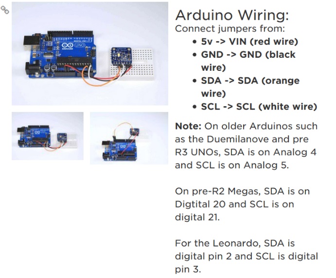
The purpose of this experiment is to find the optimal distance between the phototransistor, TCS 34725 photo transistor, and the surface of the object to be read. This distance will allow us to create a cavity on the inside of the foot with the right depth to properly house our instrumentation.
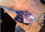
The Breadboard was set up as follows, and the guide that was followed was to set up per the adafruit directions found here:
https://learn.adafruit.com/adafruit-color-sensors/assembly-and-wiring
The Arduino Uno with an atmega328p was used as the microcontroller in this experiment. The sketch below prints the raw value of the color readings to the serial monitor.
First, a control reading was taken which grabbed the ambient color environment this value was found to be
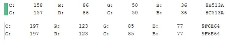
Here is also some of the raw data from the output the important data that was used in the readings was the RGB values in the columns.

After tabulating all of the raw data from the serial monitor and was put in the table below.
As shown in the table below, the delta between the green value for the control was greatest at ⅛ of an inch. However, Based on observation As the color cards were closer to the phototransistor, at a certain point the sensor did not greatly distinguish between Green and Blue Construction paper. However, this could be due to the fact that the colors used were not BOLD. Therefore, the correct materials should be used as the color sensors, such as dark construction paper. The ambient light environment the experiment was performed in may have also led to alter the results. Since an on board LED will provide the lighting source, no other ambient light is needed. Therefore, under optimal conditions the cavity in the foot will be closed and will not allow light in. However, even with external environmental light, the phototransistor will function to some degree.
| Card | Control | 2inches | 1inch | ¾ inch | ½ inch | ¼ inch | 1/8 inch |
| Red | 123 | 167 | 304 | 442 | 697 | 1712 | 7168 |
| Green | 85 | 145 | 342 | 542 | 944 | 2535 | 12658 |
| Blue | 77 | 114 | 248 | 380 | 644 | 1707 | 8312 |
As a cautionary measure, and for added flexibility the recommended distance between the phototransistor and the floor is ¼ inch. This gives us enough room adjust the distance inside the assembled foot as needed. It will also operate at this exact distance. Even though ⅛ of an inch gives us a higher delta between the control reading, the added flexibility and additional room by creating the cavity ¼ of an inch will allow us to have more options when assembling the final robot. Also, at ⅛ inch there seemed to be similar readings between green and blue construction paper. However, this could be because the color of the object used. This color differentiation problem could be mitigated when choosing final materials for the power up pad.
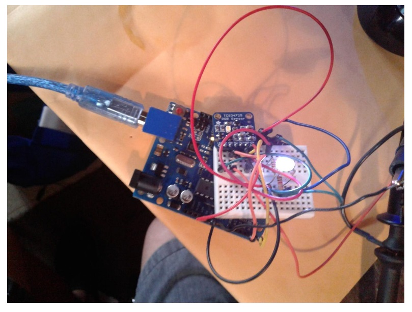
Figure 1: Realized Breadboard with RGB Matching LED
The LED is controlled using 3 digital pins from an Arduino Uno for this experiment. The functionality of controlling an indicator LED was also performed. During game play, the color will last for the duration of the power up length. This will be chosen at the discretion of the Game Committee and the Customer.
The code used was modified example code in the Adafruit_TCS34725 library.
#include <Wire.h>
#include “Adafruit_TCS34725.h”
// Pick analog outputs, for the UNO these three work well
// use ~560 ohm resistor between Red & Blue, ~1K for green (its brighter)
#define redpin 6
#define greenpin 3
#define bluepin 5
// for a common anode LED, connect the common pin to +5V
// for common cathode, connect the common to ground
// set to false if using a common cathode LED
#define commonAnode true
// our RGB -> eye-recognized gamma color
byte gammatable[256];
Adafruit_TCS34725 tcs = Adafruit_TCS34725(TCS34725_INTEGRATIONTIME_50MS, TCS34725_GAIN_4X);
void setup() {
Serial.begin(9600);
Serial.println(“Color View Test!”);
if (tcs.begin()) {
Serial.println(“Found sensor”);
} else {
Serial.println(“No TCS34725 found … check your connections”);
while (1); // halt!
}
// use these three pins to drive an LED
pinMode(redpin, OUTPUT);
pinMode(greenpin, OUTPUT);
pinMode(bluepin, OUTPUT);
// thanks PhilB for this gamma table!
// it helps convert RGB colors to what humans see
for (int i=0; i<256; i++) {
float x = i;
x /= 255;
x = pow(x, 2.5);
x *= 255;
if (commonAnode) {
gammatable[i] = 255 – x;
} else {
gammatable[i] = x;
}
//Serial.println(gammatable[i]);
}
}
void loop() {
uint16_t clear, red, green, blue;
tcs.setInterrupt(false); // turn on LED
delay(60); // takes 50ms to read
tcs.getRawData(&red, &green, &blue, &clear);
tcs.setInterrupt(true); // turn off LED
Serial.print(“C:\t”); Serial.print(clear);
Serial.print(“\tR:\t”); Serial.print(red);
Serial.print(“\tG:\t”); Serial.print(green);
Serial.print(“\tB:\t”); Serial.print(blue);
// Figure out some basic hex code for visualization
uint32_t sum = clear;
float r, g, b;
r = red; r /= sum;
g = green; g /= sum;
b = blue; b /= sum;
r *= 256; g *= 256; b *= 256;
Serial.print(“\t”);
Serial.print((int)r, HEX); Serial.print((int)g, HEX); Serial.print((int)b, HEX);
Serial.println();
delay(1500);// Added Delay in order to slow down serial monitor for reading.
//Serial.print((int)r ); Serial.print(” “); Serial.print((int)g);Serial.print(” “); Serial.println((int)b );
analogWrite(redpin, gammatable[(int)r]);
analogWrite(greenpin, gammatable[(int)g]);
analogWrite(bluepin, gammatable[(int)b]);
}
The distance range most optimal for the placement of the color sensor is between ¼ inch and ⅛ of an inch. However, in order to increase assembly flexibility and aid in final assembly the cavity containing the foot should have at least ¼ inch of separation between the sensor and the ground.
[1] https://learn.adafruit.com/adafruit-color-sensors/assembly-and-wiring
[2] https://learn.adafruit.com/adafruit-color-sensors/programming
Table of Contents
By: Brandon Perez (Missions, Systems, and Test Engineer)
Approved by: Ijya Karki (Project Manager)
Included is the post CDR updated requirements with an explanation of the quantitative values used.
Comment : The date is determined based off the class schedule and semester duration.
Comment : The budget has been determined by the customer.
Comment : These required items in our system have been set by the customer.
Comment : The speed has been determined based off the game arena dimensions, game duration, and the length of the typical expected path.
Comment : The turn angle interval has been set for the Biped to have effective turning capability when navigating the maze. The servos provided to us have mobility from 0 degrees to 180 degrees. If a turn command sets the Biped to turn at 180 degrees, then it will turn 180 degrees from where it is facing. This feature will help the Biped turn directly to the opposite direction to improve it’s agility in the game.
Comment : The distance has been determined since we expect to be sitting about 20ft away when operating the Biped during the game, “Save the Human”. The distance is yet to be determined by the game committee.
Comment : The mass has been determined by our Servo Axial Load experiment conducted by our Electronics and Controls engineer.
Comment : Colors have been selected because they are easily distinguishable from each other by the Human Vision System (HVS) when displayed on an RGB LED.
Comment : The minimum operating duration has been set by the customer.
Comment : The minimum incline and decline deviation level has been set by the customer.
Comment : The uneven surface height level has been set by The Game Committee.
Comment : This voltage rating for our DC Motor has been set because the 3Dot motor driver provides 5V. The torque rating has been set buy the minimum amount of torque required to move the legs.
Comment : The voltage rating for our servo has been because our External Power Supply with provide 5V. The torque requirement for the servo has been set by the minimum amount of torque required to shift the center-of-mass from foot to foot.
Comment : This requirement has been set so the MCU knows when our Bipeds legs have finished taking a step (half a revolution or 180 degrees) so it can stop the DC motor and shift the center-of-mass before taking the next step.
Comment : The servos being used at the feet of the Biped have been provided to us at no cost by the customer.
Comment : We have chosen a I2C compatible color sensor to be able to detect the color of the floor pads when walking over them.
Comment : We have chosen to use an IMU to sensor inclines an declines since it was provided to us at no cost by the customer.
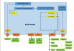
Table of Contents
By: Brandon Perez (Missions, Systems, and Test Engineer)
Approved by: Ijya Karki (Project Manager)
Included is the post CDR updated system and software block diagrams.

This is Biped’s most up-to-date System Block Diagram. Start with the 3-Dot board block diagram provided in the 3-Dot folder.
On the bottom left, you can see the Arxterra App on the Android Mobile Device communicating with the Bluetooth v4.0 BLE Transceiver on the 3Dot Board.
On the top left, we have a 7.4V Li-Ion Battery connected to an LDO 5V Regulator which then connects to the external battery connector of the 3Dot board.
On the right side of the diagram you can see our DC Motor connected to Motor A pins of the 3Dot board. Servo (arms) and Servo (body) used for shifting center of mass are attached at the servo pins of the 3Dot board.
On the bottom right, we have three sensors (IMU, Color Sensor, and Rotary Sensor) connecting directly onto the I2C Peripheral Interface pins (PWR, GND, SCL, SDA) of the 3Dot board. We also have an I2C GPIO Expander connecting the I2C Peripheral Interface to help interface with our remaining devices: Left Ankle Servo, Right Ankle Servo, and RGB LED.
What did we change from our previous design?
Now using one motor to control the walking movement to closely resemble the Theo-Jansen walking mechanism. A rotary sensor is being used instead of the optical sensor for ease of implementation and programming.
What may be subject to change?
Servos being used to control the Center of mass shifting may be removed due to our mechanical design shifting the center of mass entirely with the help of our crankshaft turning the ankles. We may not need the body servo to shift the center of mass of the system when walking on inclines since we can mechanically design our system to be stable for varying angles. If that’s the case, we would be left with an RGB LED on the GPIO expander. However completely removing the servo to shift the center of mass is unlikely. A better solution would be to use both the mechanical design and a servo to shift the center of gravity (similar to the Theo-Jansen Biped).
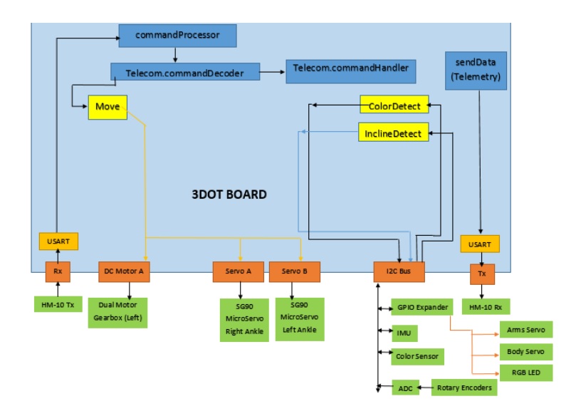
This is Biped’s most up-to-date System Software Block Diagram.
What has changed?
Our 2nd DC Motor has been taken out so our software has now changed. We are possibly not going to add any custom commands since we can ultimately utilize the parameters from sent to the predefined Move command and modify them to control our DC motor, and our 2 servos used for turning. The this will work is explained in the Arxterra Control Panel Blog post.