Fall 2016 Biped Trade Off Study- String for Lateral Balancing

Table of Contents

String Material

By: Hector Martinez (Manufacturing Engineer)
Approved by: Ijya Karki (Project Manager)

Introduction

For the Biped Project, we have considered the following materials for our Biped lateral balancing system. The system requires two weights attached to a servo through a lever and string. The purpose of this study is to choose a suitable string material to support the two weights, and allow the proper range of motion to allow the system to work properly, i.e. make the robot balance.

Material Chart

Material Costs Safe Load Pro Con
Manila Rope (Fiber Rope) $0.05 – 2.23 /ft .15kN (5mm dia)

~15.2kg

1. Durable

2. Flexible

3. Biodegradable

4. Cheap

1. Shrinks when wet

2. Difficult to unknot when wet

3. Fibrous

4. Only found in braided strands

Nylon $0.22 – 0.68 / ft .326kN (5mm dia)

~33.2kg

1. Elastic and shock absorbing

2. Long lasting

3. Rot proof

4. Chemical resistance

5. Can be bought in single strand

1. Weak against UV rays

2. Susceptible to heat

3. Loses strength when wet

Polyester $0.10 – 0.36 / ft .284kN (5mm dia)

~28.9kg

1. Rot and UV resistant

2. Retains properties wet or dry

3. Abrasion resistant

1. Not suitable for heavy duty applications

2. Susceptible to chemicals

3. not elastic, not very shock absorbent

Conclusion

Based on the research we have decided to use Nylon. The elastic and shock absorbing properties of Nylon make it perfect for a toy robot that will inevitably be used and played with and may be put through some rough times. Nylon also has the highest Safe Load rating of the three materials, and even though it is highly unlikely the rope will be used anywhere near this rating, it’s only a few cents more per square foot. The biggest reason for choosing Nylon is the ability to purchase it in a single strand. This allows us to use it in areas where space is an issue, having to use string/rope that is braided makes it difficult to use in such applications.

Resources

1. http://www.knotandrope.com/store/pc/Manila-Rope-c3.htm?pageStyle=m&ProdSort=19&page=2&idCategory=3&viewAll=yes
2. http://www.engineeringtoolbox.com/manila-rope-strength-d_1512.html
3. http://www.engineeringtoolbox.com/nylon-rope-strength-d_1513.html
4. https://knotandrope.com/store/pc/home.asp?gclid=Cj0KEQjwqfvABRC6gJ3T_4mwspoBEiQAyoQPkf52P_avp4P23eVobtda_agXx5x95YtQhVcXsBSvCBsaAkE-8P8HAQ
5. https://survivalblog.com/ropes_and_rope_making_by_be/https://www.usnetting.com/rope/selection-guide/#polyester

Fall 2016 Biped Material Trade-Off Study

Table of Contents

Building Material

By: Hector Martinez (Manufacturing Engineer)
Approved by: Ijya Karki (Project Manager)

Introduction

For the Biped Project, we have considered the following materials for manufacturing prototypes as well as for our final robot. The following chart shows advantages and disadvantages for that material.

Material Comparison Chart

Material Price Pro Con
PLA $20-165 /kg 1. Ideal for small parts2. Higher printing speed

3. Hard, soft, and flexible  variants

4. Wide range of colors

5. Plant based

1. Odor while printing2. Requires additional support while printing.

3. Some printers incapable to print PLA

4. Risks of cracks in finished product

ABS $19-175 /kg 1. Strong2. Quick solidification

3. Flexible

4. Higher temperature resistance

1. Requires heated printer bed2. Fumes while printing

3. Weak against moisture

Acrylic $3-122 /sq ft 1. High impact resistance2. Chemical resistance

3. High heat resistance

4. Weather resistance

1. Poor solvent resistance2. Subject to stress cracking

3. Low continuous service temp

Aluminum $7 / cm3 1. Strong/lightweight2. Non Magnetic

3. Electrically conductive

4. Recyclable

1. Variation in surface texture2. Expensive

3. Abrasive to tooling

Conclusion

Through careful consideration we have decided to move forward and build the Biped robot with a mix of acrylic and ABS. The use of acrylic will be more time efficient. Acrylic will allow us to quickly laser cut less intricate parts such as linkages that simply extrude outwards. The time frame to laser cut is minimal compared to the time frame to 3D print. For example, laser cutting can be accomplished in little as a minute while 3D printing could last for multiple hours. We would use ABS to produce more complicated pieces, such as the foot. The foot is considered a more complicated piece because it consists of a cut that will house the color sensor. Thus, substituting laser cutting for 3D printing intricate pieces is a more practical approach.


References

1.   http://www.3ders.org/pricecompare/
2.   http://www.absplastic.eu/pla-vs-abs-plastic-pros-cons/
3.   http://www.jwwinco.com/engineeringtips/prosconsaluminum.html
4.   http://elementaluminum.tripod.com/id8.html
5.   https://all3dp.com/metal-3d-printer-guide/
6.   https://all3dp.com/best-3d-printer-filament-types-pla-abs-pet-exotic-wood-metal/#carbon
7.   http://www.makergeeks.com/me3dprfi.html
8.   http://www.3dxtech.com/firewire-carbon-fiber-peek-3d-printing-filament/
9.   https://plastics.ulprospector.com/generics/3/acrylic
10. http://www.sdplastics.com/sdplas2.html

Servo Selection

By: Electronics and Control – Kevin Armentrout

Table of Contents

Servo Selection

Servo Selection Criteria

Servo Selection was based off of two requirements:

  • An accuracy for the servo that is within 1 degree of set-point values
  • Able to produce torque that is sufficient to actuate the position the servo will be placed
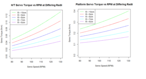
    • Head/Tail Servo Torque: 18 – 45 mN-m
    • Platform Servo Torque: 105 – 232 mN-m

From these criteria, we also had the challenge of making the servo as small as possible to allow the components to fit in the form factor of the raptor’s chassis. This limited our selection to the smallest possible servo to meet the torque and precision requirements.

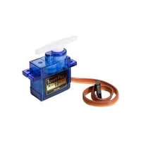
servos

The SG 90 covers both the Head and Tail servo, as well as the platform servo for the desired torques that are needed to operate those actuators. Additionally, the SG90 servos are supplied for free to the project, allowing us to meet our budget.

Source Code

Servo and Motor

# Determined by the Servo


stepSize = (pi/180)*(360/3000)

thetaHead = seq(-pi/2,pi/2,stepSize)

thetaTail = -thetaHead

thetaLeg = seq(0,2*pi,stepSize)

# In RPM

MaxSpeed = seq(80,130,.1)


# Max Incline on Y Axis


MaxY = (6.5*pi/180)


# Centripital Acceleration

# http://www.engineeringtoolbox.com/centripetal-acceleration-d_1285.html


A = (2*pi*MaxSpeed/60)^2 * Radius/100


# AA weight is 23g

# AA dimensions are in cm, which is used to determine ABS plastic

# Battery holder mass

# http://data.energizer.com/PDFs/E91.pdf


innerLength = 5.050

innerWidth = 1.450 *2

innerHeight = 1.450


outerLength = innerLength + .5

outerWidth = innerWidth + .5

outerHeight = innerHeight + .5


HolderVolume = (outerLength * outerWidth * outerHeight) – (innerLength * innerWidth * innerHeight)


AA = 23

# ABS plastic weight is .97g/cc

# http://www.stelray.com/reference-tables.html


ABSDensity = .97


# Calulate tail and head weight

# Thickness of 1cm for consistant calculations


tailMass = 2*(AA) + (Radius*(1^2) + (HolderVolume)) *ABSDensity

headMass = tailMass


# Previous Semester’s Robot Mass in grams

# https://www.arxterra.com/spring-2016-velociraptor-project-summary/#Size_Weight


Mass = 657

BodyMass = Mass – tailMass – headMass


HeadPositionX = Radius*cos(thetaHead)

HeadPositionY = Radius*sin(thetaHead)


TailPositionX = -Radius*cos(thetaTail)

TailPositionY = -Radius*sin(thetaTail)


# For moments of mass


TailMassX = TailPositionX * tailMass

TailMassY = TailPositionY * tailMass


HeadMassX = HeadPositionX * headMass

HeadMassY = HeadPositionY * headMass


X_Moment = (TailMassX + HeadMassX) / (tailMass + headMass + BodyMass)

Y_Moment = (TailMassY + HeadMassY) / (tailMass + headMass + BodyMass)


g = 9.8


LeverArm = max(Y_Moment)

# Torque due to gravity (Y Axis)


MaxTorqueHeadY = (headMass/1000) * g * Radius/100

MaxTorqueTailY = (tailMass/1000) * g * Radius/100


# Realistic torque due to gravity


RealisticTorqueHeadY = MaxTorqueHeadY * sin(MaxY)

RealisticTorqueTailY = MaxTorqueTailY * sin(MaxY)


# Torque due to Acceleration (X Axis)


MaxTorqueHeadX = (headMass/1000) * A * Radius/100

MaxTorqueTailX = (tailMass/1000) * A * Radius/100


# Platform Maximum Torque (Y Axis)


MaxTorquePlatform = MaxTorqueHeadY + MaxTorqueTailY + ((headMass/1000) * A * Radius/100) + ((tailMass/1000) * A * Radius/100)


# Frictionless Turning Torque


MaxTurningTorque = ((Mass/1000) * g) * LeverArm/100


# Frictionless Leg Moving Torque


MaxLegTorque = (Mass/2)/1000 * g * LegRadius/100

LegTorque = abs(MaxLegTorque * sin(thetaLeg))

RealMaxLegTorque = abs(MaxLegTorque * sin(60/180 * pi))


Calcs Addendum

Radius1 = 2

Radius2 = 1.5*Radius1

Radius3 = 2.25*Radius1


RPM = 32

w1 = seq(from = 0, to = -2*pi, by = -2*pi/360)

w2 = c(seq(from = 0, to = -(4/3)*pi, by = -(4/3)*pi/(2*length(w1)/3)),seq(from = -(4/3)*pi, to = -2*pi, by = -(2/3)*pi/(1*length(w1)/3)))

w2 = w2[1:length(w1)+1] – 4*pi/3

w3 = c(seq(from = 0, to = -(4/3)*pi, by = -(4/3)*pi/(2*length(w1)/3)),seq(from = (4/3)*pi, to = 0, by = -(2/3)*pi/(1*length(w1)/3)))

w3 = w3[1:length(w1)+1] – 5*pi/6


# ABS plastic weight is .97g/cc

# http://www.stelray.com/reference-tables.html


ABSDensity = .97


# Other side is roughly a quarter of scaling factor in length

massR2 = .5*(Radius2 * .25) * ABSDensity


# Other side is roughly a one and a half quarter of scaling factor in  length

massR3 = .5*(Radius3 * 1.5) * ABSDensity


# Other side is roughly a quarter of lever arm length

mass = 657

bodyMass = mass/2 – 2*(massR2 + massR3)


# Centripital Acceleration

# http://www.engineeringtoolbox.com/centripetal-acceleration-d_1285.html


A2 = (2*pi*RPM/60)^2 * Radius2/100

A3 = (2*pi*RPM/60)^2 * Radius3/100


g = 9.8


LegTorque1 = (bodyMass)/1000 * g * Radius1/100 * sin(w1)

LegTorque2 = ((massR2)/1000 * g * Radius2/100) + ((bodyMass)/1000 * g * Radius2/100 * sin(w2))

LegTorque3 = ((massR3)/1000 * g * Radius3/100) + ((bodyMass)/1000 * g * Radius3/100 * sin(w3))


LegTorque = (LegTorque1 + LegTorque2 + LegTorque3)

plot(w1, LegTorque, col = “black”, type = “o”, pch = NA, lty = 1, lwd = 2, ylab = “Torque (N-m)”, xlab = “Primary Lever Arm Position (Radians)”, main = “Leg Torque Versus Lever Arm Position”)

AverageLT = mean(LegTorque)

TorqueForCurrent = LegTorque

TorqueForCurrent[TorqueForCurrent < 0] = 0


wTip = seq(pi/2, 0,(-pi/2)/360)

TipOverTorque = 6.5/100 * g * (BodyMass/2-2*(massR2 + massR3))/1000

plot(MaxSpeed,2*MaxTorqueHeadX10, cex = .75, ylim = c(0,2*max(MaxTorqueHeadX10)), pch = “.”, col = “green”, xlab = “Servo Speed (RPM)”, ylab = “Servo Torque (N-m)”, main = ” H/T Servo Torque vs RPM at Differing H/T Radii”)

lines(MaxSpeed,2*MaxTorqueHeadX9, pch = “.”, col = “red”)

lines(MaxSpeed,2*MaxTorqueHeadX8, pch = “.”, col = “blue”)

lines(MaxSpeed,2*MaxTorqueHeadX7, pch = “.”, col = “orange”)

lines(MaxSpeed,2*MaxTorqueHeadX6, pch = “.”, col = “brown”)

lines(MaxSpeed,rep(TipOverTorque,length(MaxTorqueHeadX7)),col = “black”)

legend(“topleft”, cex =.75, lty =c(1,1,1,1,1,1), lwd = c(1,1,1,1,1,1), col = c(“green”,”red”,”blue”,”orange”,”brown”,”black”), legend = c(“R = 10cm”,”R = 9cm”,”R = 8cm”,”R = 7cm”,”R = 6cm”, “Tip Over Torque”))


thetaPlatform = seq(-6.5*pi/180, 6.5*pi/180, 1/360)

HeadPlatformPositionZ7 = 7*sin(thetaPlatform)

TailPlatformPositionZ7 = -7*sin(thetaPlatform)

HeadPlatformPositionZ6 = 6*sin(thetaPlatform)

TailPlatformPositionZ6 = -6*sin(thetaPlatform)

HeadPlatformPositionZ8 = 8*sin(thetaPlatform)

TailPlatformPositionZ8 = -8*sin(thetaPlatform)

HeadPlatformPositionZ9 = 9*sin(thetaPlatform)

TailPlatformPositionZ9 = -9*sin(thetaPlatform)

HeadPlatformPositionZ10 = 10*sin(thetaPlatform)

TailPlatformPositionZ10 = -10*sin(thetaPlatform)


plot(HeadPlatformPositionZ10, thetaPlatform*180/pi, cex = .75, xlim = c(min(TailPlatformPositionZ10),max(HeadPlatformPositionZ10)), type = “o”, pch = NA, col = “green”, xlab = “Head and Tail Position Z Axis (cm)”, ylab = “Platform Inclination (degrees)”, main = “H/T Position vs Inclination Angle”)

lines(HeadPlatformPositionZ9, thetaPlatform*180/pi, pch = “.”, col = “red”)

lines(HeadPlatformPositionZ8, thetaPlatform*180/pi, pch = “.”, col = “blue”)

lines(HeadPlatformPositionZ7, thetaPlatform*180/pi, pch = “.”, col = “orange”)

lines(HeadPlatformPositionZ6, thetaPlatform*180/pi, pch = “.”, col = “brown”)

lines(TailPlatformPositionZ10, thetaPlatform*180/pi, pch = “.”, col = “green”)

lines(TailPlatformPositionZ9, thetaPlatform*180/pi, pch = “.”, col = “red”)

lines(TailPlatformPositionZ8, thetaPlatform*180/pi, pch = “.”, col = “blue”)

lines(TailPlatformPositionZ7, thetaPlatform*180/pi, pch = “.”, col = “orange”)

lines(TailPlatformPositionZ6, thetaPlatform*180/pi, pch = “.”, col = “brown”)

legend(“topleft”, cex =.75, lty =c(1,1,1,1,1,1), lwd = c(1,1,1,1,1,1), col = c(“green”,”red”,”blue”,”orange”,”brown”), legend = c(“R = 10cm”,”R = 9cm”,”R = 8cm”,”R = 7cm”,”R = 6cm”))


ADC = seq(0,3.3,.00080)

ADC = c(ADC, rep(3.3, length(ADC)*(1/12)))

ADCRad = seq(0,2*pi, 2*pi/length(ADC))

ADCRad = ADCRad[1:length(ADCRad)-1]

plot(ADCRad, ADC, col = “black”, type = “l”, pch = NA, lty = 1, lwd = 2,  ylab = “ADC Voltage (V)”, xlab = “Primary Lever Arm Position (Radians)”, main = “A/D Voltage Versus Shaft Position”)


Motor Selection

By: Electronics and Control – Kevin Armentrout

Table of Contents

Motor Selection

Motor Selection Criteria

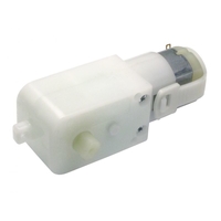
From our initial calculations in PDR, it was determined that a motor must be able to produce a minimum of 140 mN-m of torque to provide the necessary movement for the legs of the raptor. This requirement initially left us with only one option, the Tamiya 70168 gearbox motor. More research, however, uncovered another candidate for our motor selection, the GM-9 Right angle motor.

Side by side comparison with tested values:

Motor Speed INL IStall IAve Stall Torque Weight
Tamiya 70168 36 RPM 163 mA 2056 mA 763 mA 223 mN-m 160g
GM-9 RA 40 RPM 55 mA 461 mA 146 mA 311 mN-m 30g


As seen by this comparison, the GM-9 Right Angle outclassed the Tamiya 70168 in every category. In addition to this, the GM-9 Right angle also supports a voltage range from 3-6V, which will allow for the entire voltage range of the battery from 3.6V to 4.2V

Graph of Current Versus Leg Position

leg-motor

Source Code

Battery Analysis

legMaxTorque = .223

legMaxTorque2 = .311

legCurrent2 = .055 + (.461 – .055) * TorqueForCurrent/(legMaxTorque2)

legCurrent = .15 + (2.1 – .15) * TorqueForCurrent/(legMaxTorque)

legAveCurrent = mean(legCurrent)

legAveCurrent2 = mean(legCurrent2)

legCurrentPeak = .15 + (2.1 – .15) * (max(LegTorque)/legMaxTorque)

leonardo = 14*.04

IMU = .000110 +.0061 + .00065

MotorShield = .010

ServoCurrent = 2*.400


CurrentDraw = 1000*(2*legAveCurrent + leonardo + IMU + MotorShield + ServoCurrent)

plot(-w1, legCurrent, col = “black”, type = “l”, pch = NA, lty = 1, lwd = 2, ylim = c(0,2.2), ylab = “Current (A)”, xlab = “Primary Lever Arm Position (Radians)”, main = “Leg Motor Current Versus Lever Arm Position”)

lines(-w1, legCurrent2, col = “red”, lwd=2)

legend(“topleft”, cex =.75, lty =c(1,1), lwd = c(2,2), col = c(“black”,”red”), legend = c(“Tamiya 70168″,”GM-9 Right Angle”))

Servo and Motor


# Radius in cm of the tail


Radius = 10

LegRadius = 10


source(‘~/EE400d/Analysis/HeadandTailServoAnalysis.R’)


TailPositionX10 = TailPositionX

TailPositionY10 = TailPositionY

HeadPositionX10 = HeadPositionX

HeadPositionY10 = HeadPositionY

X_Moment10 = X_Moment

Y_Moment10 = Y_Moment

Radius10 = 10

LegRadius10 = 10

MaxTorqueHeadX10 = MaxTorqueHeadX

MaxTorquePlatform10 = MaxTorquePlatform

LegTorque10 = LegTorque

RealMaxLegTorque10 = RealMaxLegTorque

MaxTurningTorque10 = MaxTurningTorque


##


Radius = 9

LegRadius = 9


source(‘~/EE400d/Analysis/HeadandTailServoAnalysis.R’)


TailPositionX9 = TailPositionX

TailPositionY9 = TailPositionY

HeadPositionX9 = HeadPositionX

HeadPositionY9 = HeadPositionY

X_Moment9 = X_Moment

Y_Moment9 = Y_Moment

Radius9 = 9

LegRadius9 = 9

MaxTorqueHeadX9 = MaxTorqueHeadX

MaxTorquePlatform9 = MaxTorquePlatform

LegTorque9 = LegTorque

RealMaxLegTorque9 = RealMaxLegTorque

MaxTurningTorque9 = MaxTurningTorque


##


Radius = 8

LegRadius = 8


source(‘~/EE400d/Analysis/HeadandTailServoAnalysis.R’)


TailPositionX8 = TailPositionX

TailPositionY8 = TailPositionY

HeadPositionX8 = HeadPositionX

HeadPositionY8 = HeadPositionY

X_Moment8 = X_Moment

Y_Moment8 = Y_Moment

Radius8 = 8

LegRadius8 = 8

MaxTorqueHeadX8 = MaxTorqueHeadX

MaxTorquePlatform8 = MaxTorquePlatform

LegTorque8 = LegTorque

RealMaxLegTorque8 = RealMaxLegTorque

MaxTurningTorque8 = MaxTurningTorque


##

Radius = 7

LegRadius = 7


source(‘~/EE400d/Analysis/HeadandTailServoAnalysis.R’)


TailPositionX7 = TailPositionX

TailPositionY7 = TailPositionY

HeadPositionX7 = HeadPositionX

HeadPositionY7 = HeadPositionY

X_Moment7 = X_Moment

Y_Moment7 = Y_Moment

Radius7 = 7

LegRadius7 = 7

MaxTorqueHeadX7 = MaxTorqueHeadX

MaxTorquePlatform7 = MaxTorquePlatform

LegTorque7 = LegTorque

RealMaxLegTorque7 = RealMaxLegTorque

MaxTurningTorque7 = MaxTurningTorque


##

Radius = 6

LegRadius = 6


source(‘~/EE400d/Analysis/HeadandTailServoAnalysis.R’)


TailPositionX6 = TailPositionX

TailPositionY6 = TailPositionY

HeadPositionX6 = HeadPositionX

HeadPositionY6 = HeadPositionY

X_Moment6 = X_Moment

Y_Moment6 = Y_Moment

Radius6 = 6

LegRadius6 = 6

MaxTorqueHeadX6 = MaxTorqueHeadX

MaxTorquePlatform6 = MaxTorquePlatform

LegTorque6 = LegTorque

RealMaxLegTorque6 = RealMaxLegTorque

MaxTurningTorque6 = MaxTurningTorque


plot(X_Moment10,Y_Moment10, col = “green”, lwd = 5, xlab = “X Shift (cm)”, ylab = “Y Shift (cm)”, main = “CoG Shift By H/T Motion” )

lines(X_Moment9,Y_Moment9, col = “red” , lwd = 5)

lines(X_Moment8,Y_Moment8, col = “blue” , lwd = 5)

lines(X_Moment7,Y_Moment7, col = “cyan” , lwd = 5)

lines(X_Moment6,Y_Moment6, col = “purple” , lwd = 5)


legend(“topleft”, lty =c(1,1,1,1,1), lwd = c(1,1,1,1,1), col = c(“green”,”red”,”blue”,”cyan”,”purple”), legend = c(“R = 10cm”,”R = 9cm”,”R = 8cm”,”R = 7cm”,”R = 6cm”))


plot(MaxSpeed,2*MaxTorqueHeadX10, ylim = c(0,max(MaxTorqueHeadX10)), pch = “.”, col = “green”, xlab = “Servo Speed (RPM)”, ylab = “Servo Torque (N-m)”, main = ” H/T Servo Torque vs RPM at Differing Radii”)

lines(MaxSpeed,2*MaxTorqueHeadX9, pch = “.”, col = “red”)

lines(MaxSpeed,2*MaxTorqueHeadX8, pch = “.”, col = “blue”)

lines(MaxSpeed,2*MaxTorqueHeadX7, pch = “.”, col = “cyan”)

lines(MaxSpeed,2*MaxTorqueHeadX6, pch = “.”, col = “purple”)


legend(“topleft”, lty =c(1,1,1,1,1), lwd = c(1,1,1,1,1), col = c(“green”,”red”,”blue”,”cyan”,”purple”), legend = c(“R = 10cm”,”R = 9cm”,”R = 8cm”,”R = 7cm”,”R = 6cm”))


plot(MaxSpeed,MaxTorquePlatform10 , ylim = c(0,max(MaxTorquePlatform10)), pch = “.”, col = “green”, xlab = “Servo Speed (RPM)”, ylab = “Servo Torque (N-m)”, main = “Platform Servo Torque vs RPM at Differing Radii”)

lines(MaxSpeed,MaxTorquePlatform9, pch = “.”, col = “red”)

lines(MaxSpeed,MaxTorquePlatform8, pch = “.”, col = “blue”)

lines(MaxSpeed,MaxTorquePlatform7, pch = “.”, col = “cyan”)

lines(MaxSpeed,MaxTorquePlatform6, pch = “.”, col = “purple”)

legend(“topleft”, lty =c(1,1,1,1,1), lwd = c(1,1,1,1,1), col = c(“green”,”red”,”blue”,”cyan”,”purple”), legend = c(“R = 10cm”,”R = 9cm”,”R = 8cm”,”R = 7cm”,”R = 6cm”))


#plot(thetaLeg, LegTorque10 , ylim = c(min(LegTorque10),max(LegTorque10) + .1), pch = “.”, col = “green”, xlab = “Theta (Radians)”, ylab = “Motor Torque (N-m)”, main = “Leg Torque Versus Lever-Arm Angle”)

#lines(thetaLeg, rep(RealMaxLegTorque10, length(LegTorque)), col = “green”, lty = 2)

#lines(thetaLeg, LegTorque9 , ylim = c(min(LegTorque10),max(LegTorque9)), col = “red”)

#lines(thetaLeg, rep(RealMaxLegTorque9, length(LegTorque)), col = “red”, lty = 2)

#lines(thetaLeg, LegTorque8 , ylim = c(min(LegTorque8),max(LegTorque9)), col = “blue”)

#lines(thetaLeg, rep(RealMaxLegTorque8, length(LegTorque)), col = “blue”, lty = 2)

#lines(thetaLeg, LegTorque7 , ylim = c(min(LegTorque7),max(LegTorque9)), col = “cyan”)

#lines(thetaLeg, rep(RealMaxLegTorque7, length(LegTorque)), col = “cyan”, lty = 2)

#lines(thetaLeg, LegTorque6 , ylim = c(min(LegTorque6),max(LegTorque9)), col = “purple”)

#lines(thetaLeg, rep(RealMaxLegTorque6, length(LegTorque)), col = “purple”, lty = 2)

#legend(“topleft”, lty =c(1,1,1,1,1), lwd = c(1,1,1,1,1), col = c(“green”,”red”,”blue”,”cyan”,”purple”), legend = c(“R = 10cm”,”R = 9cm”,”R = 8cm”,”R = 7cm”,”R = 6cm”))


Calcs Addendum

Radius1 = 2

Radius2 = 1.5*Radius1

Radius3 = 2.25*Radius1


RPM = 32

w1 = seq(from = 0, to = -2*pi, by = -2*pi/360)

w2 = c(seq(from = 0, to = -(4/3)*pi, by = -(4/3)*pi/(2*length(w1)/3)),seq(from = -(4/3)*pi, to = -2*pi, by = -(2/3)*pi/(1*length(w1)/3)))

w2 = w2[1:length(w1)+1] – 4*pi/3

w3 = c(seq(from = 0, to = -(4/3)*pi, by = -(4/3)*pi/(2*length(w1)/3)),seq(from = (4/3)*pi, to = 0, by = -(2/3)*pi/(1*length(w1)/3)))

w3 = w3[1:length(w1)+1] – 5*pi/6


# ABS plastic weight is .97g/cc

# http://www.stelray.com/reference-tables.html


ABSDensity = .97


# Other side is roughly a quarter of scaling factor in length

massR2 = .5*(Radius2 * .25) * ABSDensity


# Other side is roughly a one and a half quarter of scaling factor in  length

massR3 = .5*(Radius3 * 1.5) * ABSDensity


# Other side is roughly a quarter of lever arm length

mass = 657

bodyMass = mass/2 – 2*(massR2 + massR3)


# Centripital Acceleration

# http://www.engineeringtoolbox.com/centripetal-acceleration-d_1285.html


A2 = (2*pi*RPM/60)^2 * Radius2/100

A3 = (2*pi*RPM/60)^2 * Radius3/100


g = 9.8


LegTorque1 = (bodyMass)/1000 * g * Radius1/100 * sin(w1)

LegTorque2 = ((massR2)/1000 * g * Radius2/100) + ((bodyMass)/1000 * g * Radius2/100 * sin(w2))

LegTorque3 = ((massR3)/1000 * g * Radius3/100) + ((bodyMass)/1000 * g * Radius3/100 * sin(w3))


LegTorque = (LegTorque1 + LegTorque2 + LegTorque3)

plot(w1, LegTorque, col = “black”, type = “o”, pch = NA, lty = 1, lwd = 2, ylab = “Torque (N-m)”, xlab = “Primary Lever Arm Position (Radians)”, main = “Leg Torque Versus Lever Arm Position”)

AverageLT = mean(LegTorque)

TorqueForCurrent = LegTorque

TorqueForCurrent[TorqueForCurrent < 0] = 0


wTip = seq(pi/2, 0,(-pi/2)/360)

TipOverTorque = 6.5/100 * g * (BodyMass/2-2*(massR2 + massR3))/1000

plot(MaxSpeed,2*MaxTorqueHeadX10, cex = .75, ylim = c(0,2*max(MaxTorqueHeadX10)), pch = “.”, col = “green”, xlab = “Servo Speed (RPM)”, ylab = “Servo Torque (N-m)”, main = ” H/T Servo Torque vs RPM at Differing H/T Radii”)

lines(MaxSpeed,2*MaxTorqueHeadX9, pch = “.”, col = “red”)

lines(MaxSpeed,2*MaxTorqueHeadX8, pch = “.”, col = “blue”)

lines(MaxSpeed,2*MaxTorqueHeadX7, pch = “.”, col = “orange”)

lines(MaxSpeed,2*MaxTorqueHeadX6, pch = “.”, col = “brown”)

lines(MaxSpeed,rep(TipOverTorque,length(MaxTorqueHeadX7)),col = “black”)

legend(“topleft”, cex =.75, lty =c(1,1,1,1,1,1), lwd = c(1,1,1,1,1,1), col = c(“green”,”red”,”blue”,”orange”,”brown”,”black”), legend = c(“R = 10cm”,”R = 9cm”,”R = 8cm”,”R = 7cm”,”R = 6cm”, “Tip Over Torque”))


thetaPlatform = seq(-6.5*pi/180, 6.5*pi/180, 1/360)

HeadPlatformPositionZ7 = 7*sin(thetaPlatform)

TailPlatformPositionZ7 = -7*sin(thetaPlatform)

HeadPlatformPositionZ6 = 6*sin(thetaPlatform)

TailPlatformPositionZ6 = -6*sin(thetaPlatform)

HeadPlatformPositionZ8 = 8*sin(thetaPlatform)

TailPlatformPositionZ8 = -8*sin(thetaPlatform)

HeadPlatformPositionZ9 = 9*sin(thetaPlatform)

TailPlatformPositionZ9 = -9*sin(thetaPlatform)

HeadPlatformPositionZ10 = 10*sin(thetaPlatform)

TailPlatformPositionZ10 = -10*sin(thetaPlatform)


plot(HeadPlatformPositionZ10, thetaPlatform*180/pi, cex = .75, xlim = c(min(TailPlatformPositionZ10),max(HeadPlatformPositionZ10)), type = “o”, pch = NA, col = “green”, xlab = “Head and Tail Position Z Axis (cm)”, ylab = “Platform Inclination (degrees)”, main = “H/T Position vs Inclination Angle”)

lines(HeadPlatformPositionZ9, thetaPlatform*180/pi, pch = “.”, col = “red”)

lines(HeadPlatformPositionZ8, thetaPlatform*180/pi, pch = “.”, col = “blue”)

lines(HeadPlatformPositionZ7, thetaPlatform*180/pi, pch = “.”, col = “orange”)

lines(HeadPlatformPositionZ6, thetaPlatform*180/pi, pch = “.”, col = “brown”)

lines(TailPlatformPositionZ10, thetaPlatform*180/pi, pch = “.”, col = “green”)

lines(TailPlatformPositionZ9, thetaPlatform*180/pi, pch = “.”, col = “red”)

lines(TailPlatformPositionZ8, thetaPlatform*180/pi, pch = “.”, col = “blue”)

lines(TailPlatformPositionZ7, thetaPlatform*180/pi, pch = “.”, col = “orange”)

lines(TailPlatformPositionZ6, thetaPlatform*180/pi, pch = “.”, col = “brown”)

legend(“topleft”, cex =.75, lty =c(1,1,1,1,1,1), lwd = c(1,1,1,1,1,1), col = c(“green”,”red”,”blue”,”orange”,”brown”), legend = c(“R = 10cm”,”R = 9cm”,”R = 8cm”,”R = 7cm”,”R = 6cm”))


ADC = seq(0,3.3,.00080)

ADC = c(ADC, rep(3.3, length(ADC)*(1/12)))

ADCRad = seq(0,2*pi, 2*pi/length(ADC))

ADCRad = ADCRad[1:length(ADCRad)-1]

plot(ADCRad, ADC, col = “black”, type = “l”, pch = NA, lty = 1, lwd = 2,  ylab = “ADC Voltage (V)”, xlab = “Primary Lever Arm Position (Radians)”, main = “A/D Voltage Versus Shaft Position”)


IMU Selection

By: Electronics and Control – Kevin Armentrout

Table of Contents

IMU Selection

IMU Selection Criteria

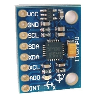
IMU Selection was based off the requirement for angle accuracies to the Hundredth of a degree and the IMU must utilize I2C. For I2C IMUs this left us two option, the MPU 6050 and the LSM9DS1. The LSM9DS1 was the option that the previous semester’s raptor used, and utilizing it caused problems with accuracy. That problem is exacerbated by the fact the LSM9DS1 only supports 2g and 200 degree/s natively. The MPU 6050 supports 2-16g and 2000 degree/s. This led to the choice to use the MPU 6050 rather than the LSM9DS1.

IMU Testing

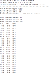
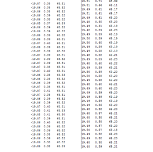
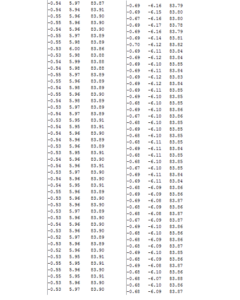
IMU testing was conducted using Steady State operation, a 20 degree roll, and a 6 degree pitch. After Calibration the IMU produced the following results:

1-number

IMU Steady State and Initialization

2-number

20 Degree Roll Left and Right

3-number

6 Degree Inclination and Declination

Results

The IMU produced the following errors when compared to expected values:

IMU Testing
Test X Y Z
Steady State 0.113° (MAE) 0.02° (MAE) 0.13%
6 Degree Decline 0.54° (MAE) 2.60% 0.13%
6 Degree Incline 0.69° (MAE) 0.65% 0.14%
20 Degree Roll Left 0.67% 0.58° (MAE) 1.14%
20 Degree Roll Right 1.13% 0.40° (MAE) 1.67%


The IMU had excellent accuracy when compared to actual values, making it the ideal selection choice for the I2C IMU.

Rotary Sensors and I2C D/A

By: Electronics and Control – Kevin Armentrout

Table of Contents

Rotary Sensors and I2C D/A

Requirements

The rotary sensors requirement is the derivation of the requirement for shaft position indication. Shaft position indication is needed as it roughly translates to leg position. This allows the raptor the position its leg to the desired spots for a continuous leg motion.

Why not a Rotary Encoder?

A rotary encoder would be the typical solution to this problem, but a rotary encoder has two major flaws.

  • A rotary encoder must use interrupts to trigger an event when the encoder generates a Gray Code pulse
  • Rotary encoders have limited resolution.

The need for external interrupts conflicts with our requirement to use the 3DoT board, and the Resolution limitation conflicts with our 1-degree resolution requirement.

Continuous Motion Potentiometers

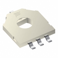
Continuous Motion Potentiometers, fulfil the above requirements for resolution and requires no additional interrupts to read. Continuous motion potentiometers are typically used on servos for precise position indication. The major downside to these potentiometers as a method of position control is that the indication requires an Analog to Digital converter, and the 3DoT board is fresh out of those.

I2C Digital to Analog Converters

The digital to analog converters that need to be used for our project must be I2C compatible. From there, the converter must have a least 1-degree resolution when converting the analog signal to digital.

Component Selection

With these requirements in mind, we selected the Bourne 3382 Series and the ADS-1015. These are the least expensive option that also fits meets our resolution requirements:

  • Sensitivity at 3.3v:
    • .81 mV
  • Sensitivity of Shaft Indication:
    • .088 Degrees

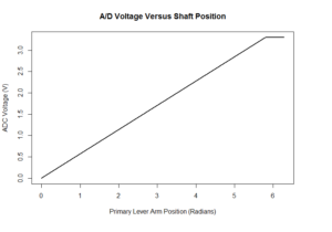
The major downside to this selection choice is that the Bourne 3382 has a dead band from 330-360 degrees. A/D resolution and accuracy is shown below:

graph-rotary-sensors

Debugging Wire Library

By: Electronics and Control Engineer – Kevin Armentrout

Table of Contents

Debugging the Wire Library

Problems with the Wire Library and the 3DoT library

The wire library uses an inefficient system of transferring data via I2c which can be interrupted during serial communications. When this happens your 3DoT program, and any other Arduino program that is using both of these communication methods will freeze. This is a very difficult problem to experience and diagnose as it may be the most frustrating thing you can experience, an intermittent bug.

Fortunately, the solution is available, but it requires modifying the header files of any I2c implemented device to ensure that the libraries are compatible. I modified the MPU-6050 library to prevent this run-over and implemented the time-out that is available in the I2C Master library. This eliminated all bugs associated with I2C and serial communications that I had experienced. The I2C Master library is found here. Completion of this interface between the 3DoT library and the I2C library accomplishes the IMU action item.

Project Source Code Gyro Debugging:

/* Author = helscream (Omer Ikram ul Haq)
Last edit date = 2014-10-08
Website: http://hobbylogs.me.pn/?p=47
Location: Pakistan
Ver: 0.1 beta — Start
Ver: 0.2 beta — Bug fixed for calculating “angle_y_accel” and “angle_x_accel” in “Gyro_header.ino” file
*/

#ifndef gyro_accel.h
#define gyro_accel.h

extern int accel_x_OC, accel_y_OC, accel_z_OC, gyro_x_OC ,gyro_y_OC, gyro_z_OC; // offset variables
extern float temp_scalled,accel_x_scalled,accel_y_scalled,accel_z_scalled,gyro_x_scalled,gyro_y_scalled,gyro_z_scalled; //Scaled Data variables

void MPU6050_ReadData();
void MPU6050_ResetWake();
void MPU6050_SetDLPF(int BW);
void MPU6050_SetGains(int gyro,int accel);
void MPU6050_OffsetCal();

#endif


/* Author = helscream (Omer Ikram ul Haq)
Last edit date = 2014-10-08
Website: http://hobbylogs.me.pn/?p=47
Location: Pakistan
Ver: 0.1 beta — Start
Ver: 0.2 beta — Bug fixed for calculating “angle_y_accel” and “angle_x_accel” in “Gyro_header.ino” file
*/

#include <Arduino.h>
#include <Wire.h>
#include “gyro_accel.h”
#include “I2C.h”

// Defining the important registers

#define MPU6050_address 0x68

// —— SELF Test Trim Factors ———————-
#define MPU6050_self_test_x 13       // R/W
#define MPU6050_self_test_y 14       // R/W
#define MPU6050_self_test_z 15       // R/W
#define MPU6050_self_test_A 16       // R/W

// —– Sample Divider ——————————-
#define MPU6050_sample_div 25        // R/W
/*       Sample Divider Discription
Sample rate = 8/(1 + Sample rate divider) [kHz]  if DLPF is disabled
Sample rate = 1/(1 + Sample rate divider) [kHz]  if DLPF is enabled
*/

// —– Configration ———————————
#define MPU6050_config 26            // R/W
#define MPU6050_gyro_config 27       // R/W
#define MPU6050_accel_config 28      // R/W

// —– Data ———————————————
#define MPU6050_data_start 59
#define read_bytes 14

// —– Power Management ———————————
#define MPU6050_PWR1 107
#define MPU6050_PWR2 108

// —– Defining Constant ——————————–
#define g 9.81                       // Gravitational accelration

// Variables
int temp=0, accel_x=0, accel_y=0, accel_z=0, gyro_x=0, gyro_y=0, gyro_z=0; // Raw values varaibles
int accel_x_OC=0, accel_y_OC=0, accel_z_OC=0, gyro_x_OC=0 ,gyro_y_OC=0, gyro_z_OC=0; // offset variables
float temp_scalled,accel_x_scalled,accel_y_scalled,accel_z_scalled,gyro_x_scalled,gyro_y_scalled,gyro_z_scalled; //Scalled Data varaibles
float accel_scale_fact = 1, gyro_scale_fact = 1; // Scale factor variables

// **************************************************************************
//          Functions for MPU6050
// **************************************************************************

void MPU6050_ReadData(){

//Wire.beginTransmission(MPU6050_address);
//Wire.write(MPU6050_data_start);
//Wire.endTransmission();

I2c.write(MPU6050_address, MPU6050_data_start);

//int read_bytes = 14;

//Wire.requestFrom(MPU6050_address,read_bytes);
I2c.read(MPU6050_address,read_bytes);

if(I2c.available() == read_bytes){

accel_x = I2c.receive()<<8 | I2c.receive();
accel_y = I2c.receive()<<8 | I2c.receive();
accel_z = I2c.receive()<<8 | I2c.receive();

temp = I2c.receive()<<8 | I2c.receive();

gyro_x = I2c.receive()<<8 | I2c.receive();
gyro_y = I2c.receive()<<8 | I2c.receive();
gyro_z = I2c.receive()<<8 | I2c.receive();

}

/*   if(Wire.available() == read_bytes){

accel_x = Wire.read()<<8 | Wire.read();
accel_y = Wire.read()<<8 | Wire.read();
accel_z = Wire.read()<<8 | Wire.read();

temp = Wire.read()<<8 | Wire.read();

gyro_x = Wire.read()<<8 | Wire.read();
gyro_y = Wire.read()<<8 | Wire.read();
gyro_z = Wire.read()<<8 | Wire.read();

} */

accel_x_scalled = (float)(accel_x-accel_x_OC)*accel_scale_fact/1000; // divided by 1000 as the Scale factor is in milli units
accel_y_scalled = (float)(accel_y-accel_y_OC)*accel_scale_fact/1000;
accel_z_scalled = (float)(accel_z-accel_z_OC)*accel_scale_fact/1000;

gyro_x_scalled = (float)(gyro_x-gyro_x_OC)*gyro_scale_fact/1000;
gyro_y_scalled = (float)(gyro_y-gyro_y_OC)*gyro_scale_fact/1000;
gyro_z_scalled = ((float)(gyro_z-gyro_z_OC)*gyro_scale_fact/1000);

temp_scalled = (float)temp/340+36.53;
}

// ————————————————
//       Reset and wake up the MPU6050
// ————————————————
void MPU6050_ResetWake(){

Serial.println(“Resetting MPU6050 and waking it up…..”);
Wire.beginTransmission(MPU6050_address);
Wire.write(MPU6050_PWR1);
Wire.write(0b10000000);
Wire.endTransmission();

delay(100); // Waiting for the reset to complete

Wire.beginTransmission(MPU6050_address);
Wire.write(MPU6050_PWR1);

Wire.write(0b00000000);
Wire.endTransmission();

}

// ————————————————
//       Setting up the DLFP
// ————————————————

void MPU6050_SetDLPF(int BW)
{
if (BW < 0 || BW > 6){
BW = 0;
}
Wire.beginTransmission(MPU6050_address);
Wire.write(MPU6050_config); // Address to the configuration register
/*       config Discription —- x x 0 0 0 F2 F1 F0
I am only intrested in the Digital Low Pass Filter (DLPF)
F2 F1 F0    Bandwidth [Hz]
0  0  0
0  0  1      184
0  1  0      94
0  1  1      44
1  0  0      21
1  0  1      10
1  1  0      5
*/

Wire.write(BW);
Wire.endTransmission();
}

// ————————————————
//       Setting up the Accelrometer and Gyro Gains
// ————————————————

void MPU6050_SetGains(int gyro,int accel)
{
byte gyro_byte,accel_byte;

// Setting up Gyro
Wire.beginTransmission(MPU6050_address);
Wire.write(MPU6050_gyro_config); // Address to the configuration register
if (gyro==0)
{
gyro_scale_fact =(float)250*0.0305; // each data is of 16 bits that means, 250 is divided along 2^(15)-1 = 32767 so for milli degree/s 0.0305 = 1000/32767
gyro_byte = 0b00000000;
}else if (gyro == 1)
{
gyro_scale_fact = 500*0.0305; // each data is of 16 bits that means, 500 is divided along 2^(15)-1 = 32767 so for milli degree/s 0.0305 = 1000/32767
gyro_byte = 0b00001000;
}else if (gyro == 2)
{
gyro_scale_fact = 1000*0.0305;// each data is of 16 bits that means, 1000 is divided along 2^(15)-1 = 32767 so for milli degree/s 0.0305 = 1000/32767
gyro_byte = 0b00010000;
}else if (gyro == 3)
{
gyro_scale_fact = 2000*0.0305;  // each data is of 16 bits that means, 2000 is divided along 2^(15)-1 = 32767 so for milli degree/s 0.0305 = 1000/32767
gyro_byte = 0b00011000;
}else
{
gyro_scale_fact = 1;
}

Wire.write(gyro_byte);
Wire.endTransmission();
Serial.print(“The gyro scale is set to “);
Serial.print(gyro_scale_fact);
Serial.println(” milli Degree/s”);

// Setting up Accel
Wire.beginTransmission(MPU6050_address);
Wire.write(MPU6050_accel_config); // Address to the configuration register
if (accel==0)
{
accel_scale_fact =(float)2*g*0.0305; // each data is of 16 bits that means, 2g is divided along 2^(15)-1 = 32767 so for milli m/s^2 0.0305 = 1000/32767
accel_byte = 0b00000000;
}else if (accel == 1)
{
accel_scale_fact = 4*g*0.0305; // each data is of 16 bits that means, 4g is divided along 2^(15)-1 = 32767 so for milli m/s^2 0.0305 = 1000/32767
accel_byte = 0b00001000;
}else if (accel == 2)
{
accel_scale_fact = 8*g*0.0305;// each data is of 16 bits that means, 8g is divided along 2^(15)-1 = 32767 so for milli m/s^2 0.0305 = 1000/32767
accel_byte = 0b00010000;
}else if (accel == 3)
{
accel_scale_fact = 16*g*0.0305; // each data is of 16 bits that means, 16g is divided along 2^(15)-1 = 32767 so for milli m/s^2 0.0305 = 1000/32767
accel_byte = 0b00011000;
}else
{
accel_scale_fact = 1;
}

Wire.write(accel_byte);
Wire.endTransmission();
Serial.print(“The accel scale is set to “);
Serial.print(accel_scale_fact);
Serial.println(” milli m/s^2″);

}

// ————————————————
//       offset calibration
// ————————————————

void MPU6050_OffsetCal(){
Serial.println(“Calibrating gyroscope …. dont move the hardware ……….”);

int x=0,y=0,z=0,i;

MPU6050_ReadData();
MPU6050_ReadData();

// Gyro Offset Calculation
x=gyro_x;
y=gyro_y;
z=gyro_z;

for (i=1;i<=1000;i++){
MPU6050_ReadData();
x=(x+gyro_x)/2;
y=(y+gyro_y)/2;
z=(z+gyro_z)/2;
Serial.print(“.”);
}
Serial.println(“.”);
gyro_x_OC=x;
gyro_y_OC=y;
gyro_z_OC=z;

Serial.print(“gyro_x register offset = “);
Serial.println(x);

Serial.print(“gyro_y register offect = “);
Serial.println(y);

Serial.print(“gyro_z register offset = “);
Serial.println(z);

// Accel Offset Calculation
Serial.println(“Calibrating accelrometer …. dont move the hardware ……….”);
x=accel_x;
y=accel_y;
z=accel_z;

for (i=1;i<=1000;i++){
MPU6050_ReadData();
x=(x+accel_x)/2;
y=(y+accel_y)/2;
z=(z+accel_z)/2;
Serial.print(“.”);
}
Serial.println(“.”);
accel_x_OC=x;
accel_y_OC=y;
accel_z_OC=z-(float)g*1000/accel_scale_fact;

Serial.print(“Accel_x register offset = “);
Serial.println(x);

Serial.print(“Accel_y register offect = “);
Serial.println(y);

Serial.print(“Accel_z register offset = “);
Serial.println(z);

}

Telemetry Custom Commands

/*

* Telemetry and Custom Command Sample Arduino Code

*   Telemetry Example: Monitor an extended I/O register value and send to control panel display

*   Command Example:   Add Robot unique MOVE, BLINK, and SERVO commands

*/


#include <Robot3DoTBoard.h>     // instantiated as Robot3DoT at end of class header


#include <EEPROM.h>

//#include <Wire.h>               // I2C support

#include <Servo.h>

#include <I2C.h>


// IMU Variables


#include “gyro_accel.h”

// Defining constants

#define IMUdt 20                       // time difference in milli seconds

#define rad2degree 57.3              // Radian to degree conversion

#define Filter_gain 0.95             // e.g.  angle = angle_gyro*Filter_gain + angle_accel*(1-Filter_gain)


// *********************************************************************

//    Global IMU Variables

// *********************************************************************

unsigned long IMUt=0; // Time Variables

float angle_x_gyro=0,angle_y_gyro=0,angle_z_gyro=0,angle_x_accel=0,angle_y_accel=0,angle_z_accel=0,angle_x=0,angle_y=0,angle_z=0;

// *********************************************************************


// Motor Variables


int Motor1F = 5;

int Motor1R = 10;

int Motor1PWM = A9;

volatile int Motor1Speed = 0;


int Motor2F = 19;

int Motor2R = 20;

int Motor2PWM = 6;

volatile int Motor2Speed = 0;


volatile int Mot1State = 0;

volatile int Mot2State = 0;

long HoldTime = micros();


// Servo Variables


//


Robot3DoTBoard Robot3DoT;       // instantiated as Robot3DoT at end of class header


/*

* Command Example

* Step 1: Assign new command mnemonics ID numbers

*         In our example we will be adding 3 custom commands (2 new and one predefined).

*         The predefined MOVE command is intercepted and our robot unique code is to be

*         run instead. The MOVE command mnemonic ID 0x01 is already defined in Configure.h

*         The next two commands are new and assigned to the first two addresses in the

*         custom command address space 0x40 – 0x5F.

*/


#define DYNSTAT       0x41

const uint8_t CMD_LIST_SIZE = 2;   // we are adding 3 commands (MOVE, BLINK, SERVO)


/*

* Command Example

* Step 2: Register commands by linking IDs to their corresponding command handlers

*         In our example when the MOVE command is intercepted the moveHandler is to be run.

*         In a similar fashion the BLINK command calls the blinkHandler and SERVO the

*         servoHandler.

*/


void moveHandler (uint8_t cmd, uint8_t param[], uint8_t n);

void dynstatHandler (uint8_t cmd, uint8_t param[], uint8_t n);


Robot3DoTBoard::cmdFunc_t onCommand[CMD_LIST_SIZE] = {{MOVE,moveHandler}, {DYNSTAT,dynstatHandler}};


/*

* Telemetry Example

* Step 1: Instantiate packet

*         In our example we simulate a current sensor wired to MOTOR 2. MOTOR2_CURRENT_ID

*         is defined as 0x02 in Configure.h

*         To simulate the data stream coming from the sensor we will read ATmega32U4

*         Register OCR4D which controls the duty cycle of MOTOR 2.

*/

Packet motorPWM(MOTOR2_CURRENT_ID);  // initialize the packet properties to default values


void setup()

{

Serial.begin(38400);               // default = 115200


Robot3DoT.begin();


// Initialize Motor To Off


pinMode(Motor1F, OUTPUT);

pinMode(Motor1R, OUTPUT);

pinMode(Motor1PWM, OUTPUT);


pinMode(Motor2F, OUTPUT);

pinMode(Motor2R, OUTPUT);

pinMode(Motor2PWM, OUTPUT);


digitalWrite(Motor1F,LOW);

digitalWrite(Motor1R,LOW);


digitalWrite(Motor2F,LOW);

digitalWrite(Motor2R,LOW);


// Initialize IMU


Serial.begin(9600);

I2c.begin();

I2c.timeOut(100);

MPU6050_ResetWake();

MPU6050_SetGains(0,1);// Setting the lows scale

MPU6050_SetDLPF(0); // Setting the DLPF to inf Bandwidth for calibration

MPU6050_OffsetCal();

MPU6050_SetDLPF(6); // Setting the DLPF to lowest Bandwidth

IMUt=millis();


/*

* Command Example

* Step 3: Tell 3DoT Robot software about new commands

*

*

*/


Robot3DoT.setOnCommand(onCommand, CMD_LIST_SIZE);


/* Telemetry Example

* Step 2: Modify default values assigned to internal properties as needed.

*         Before a packet is created and sent, it is qualified. Specifically,

*         the data in a packet must change by some amount from the previous

*         packet and may not be sent with at a period less than some value.

*         In most cases you can leave these values at their default values.

*/

delay(1000);

}


void loop()

{

Robot3DoT.loop();

// Set Motor State to the Telemetry Read Value


if (Mot1State == 1){ digitalWrite(Motor1F,HIGH);

digitalWrite(Motor1R,LOW);

} else if (Mot1State == 2) { digitalWrite(Motor1F,LOW);

digitalWrite(Motor1R,HIGH);

}                                 else {digitalWrite(Motor1F,LOW);

digitalWrite(Motor1R,LOW);}


if (Mot2State == 1){  digitalWrite(Motor2F,HIGH);

digitalWrite(Motor2R,LOW);

} else if (Mot2State == 2) { digitalWrite(Motor2F,LOW);

digitalWrite(Motor2R,HIGH);

}                                 else {digitalWrite(Motor2F,LOW);

digitalWrite(Motor2R,LOW);}


analogWrite(Motor1PWM, Motor1Speed);

analogWrite(Motor2PWM, Motor2Speed);

if (micros() – HoldTime > 500000){

HoldTime = micros();

//  Serial.write(“”);

//  Serial.write(Mot1State);

//  Serial.write(Motor1Speed);

//  Serial.write(Mot2State);

//  Serial.write(Motor2Speed);

//  Serial.write(“”);


Serial.print(angle_x);

Serial.print(“\t”);

Serial.print(angle_y);

Serial.print(“\t”);

Serial.print(angle_z);

Serial.println();

}

// Read IMU Settings


//if (millis() – IMUt > IMUdt){

IMU();

//}


// Set Servos to IMU Setting


}


/*

* Command Example

* Step 4: Write command handlers

*/


/*

* User Defined Command BLINK (0x40) Example

* A5 01 40 E4

*/


/*

* Override MOVE (0x01) Command Example

* A5 05 01 01 80 01 80 A1

*/

void moveHandler (uint8_t cmd, uint8_t param[], uint8_t n)

{

Mot1State = param[0];

Mot2State = param[2];


// Configure Inputs and Output


Motor1Speed = param[1];

Motor2Speed = param[3];

Serial.write(cmd);             // move command = 0x01

Serial.write(n);               // number of param = 4

for (int i=0;i<n;i++)          // param = 01 80 01 80

{

Serial.write (param[i]);

}


}                                // moveHandler


/*

* User Defined Command SERVO (0x41) Example

* Rotate servo to 90 degrees

* A5 02 41 90 76

*/

void dynstatHandler (uint8_t cmd, uint8_t param[], uint8_t n)

{

Serial.write(cmd);             // servo command = 0x41

Serial.write(n);               // number of param = 1

for (int i=0;i<n;i++)          // param = 90 degrees

{

Serial.write (param[i]);

}


}  // servoHandler


void IMU(){

IMUt=millis();


MPU6050_ReadData();


angle_x_gyro = (gyro_x_scalled*((float)IMUdt/1000)+angle_x);

angle_y_gyro = (gyro_y_scalled*((float)IMUdt/1000)+angle_y);

angle_z_gyro = (gyro_z_scalled*((float)IMUdt/1000)+angle_z);


angle_z_accel = atan(accel_z_scalled/(sqrt(accel_y_scalled*accel_y_scalled+accel_x_scalled*accel_x_scalled)))*(float)rad2degree;

angle_y_accel = -atan(accel_y_scalled/(sqrt(accel_y_scalled*accel_y_scalled+accel_z_scalled*accel_z_scalled)))*(float)rad2degree;

angle_x_accel = atan(accel_x_scalled/(sqrt(accel_x_scalled*accel_x_scalled+accel_z_scalled*accel_z_scalled)))*(float)rad2degree;


angle_x = Filter_gain*angle_x_gyro+(1-Filter_gain)*angle_x_accel;

angle_y = Filter_gain*angle_y_gyro+(1-Filter_gain)*angle_y_accel;

angle_z = Filter_gain*angle_z_gyro+(1-Filter_gain)*angle_z_accel;


//  Serial.print(gyro_x_scalled);

//  Serial.print(“\t”);

//  Serial.print(gyro_y_scalled);

//  Serial.print(“\t”);

//  Serial.print(gyro_z_scalled);

//  Serial.print(“\t”);

//

//

//  Serial.print(accel_x_scalled);

//  Serial.print(“\t”);

//  Serial.print(accel_y_scalled);

//  Serial.print(“\t”);

//  Serial.print(accel_z_scalled);

//  Serial.print(“\t”);

//

//  Serial.print(angle_x_gyro);

//  Serial.print(“\t”);

//  Serial.print(angle_y_gyro);

//  Serial.print(“\t”);

//  Serial.print(angle_z_gyro);

//  Serial.print(“\t”);

//

//  Serial.print(angle_x_accel);

//  Serial.print(“\t”);

//  Serial.print(angle_y_accel);

//  Serial.print(“\t”);

//  Serial.print(angle_z_accel);

//  Serial.print(“\t”);


//  Serial.print(angle_x);

//  Serial.print(“\t”);

//  Serial.print(angle_y);

//  Serial.print(“\t”);

//  Serial.print(angle_z);

//  Serial.println();


//  Serial.println(((float)(millis()-IMUt)/(float)IMUdt)*100);

}


Modified gyro_accel.cpp:

/* Author = helscream (Omer Ikram ul Haq)

Last edit date = 2014-10-08

Website: http://hobbylogs.me.pn/?p=47

Location: Pakistan

Ver: 0.1 beta — Start

Ver: 0.2 beta — Bug fixed for calculating “angle_y_accel” and “angle_x_accel” in “Gyro_header.ino” file

*/


#include <Arduino.h>

#include <Wire.h>

#include “gyro_accel.h”

#include “I2C.h”


// Defining the important registers


#define MPU6050_address 0x68


// —— SELF Test Trim Factors ———————-

#define MPU6050_self_test_x 13       // R/W

#define MPU6050_self_test_y 14       // R/W

#define MPU6050_self_test_z 15       // R/W

#define MPU6050_self_test_A 16       // R/W


// —– Sample Divider ——————————-

#define MPU6050_sample_div 25        // R/W

/*       Sample Divider Discription

Sample rate = 8/(1 + Sample rate divider) [kHz]  if DLPF is disabled

Sample rate = 1/(1 + Sample rate divider) [kHz]  if DLPF is enabled

*/


// —– Configration ———————————

#define MPU6050_config 26            // R/W

#define MPU6050_gyro_config 27       // R/W

#define MPU6050_accel_config 28      // R/W


// —– Data ———————————————

#define MPU6050_data_start 59

#define read_bytes 14


// —– Power Management ———————————

#define MPU6050_PWR1 107

#define MPU6050_PWR2 108


// —– Defining Constant ——————————–

#define g 9.81                       // Gravitational accelration


// Variables

int temp=0, accel_x=0, accel_y=0, accel_z=0, gyro_x=0, gyro_y=0, gyro_z=0; // Raw values varaibles

int accel_x_OC=0, accel_y_OC=0, accel_z_OC=0, gyro_x_OC=0 ,gyro_y_OC=0, gyro_z_OC=0; // offset variables

float temp_scalled,accel_x_scalled,accel_y_scalled,accel_z_scalled,gyro_x_scalled,gyro_y_scalled,gyro_z_scalled; //Scalled Data varaibles

float accel_scale_fact = 1, gyro_scale_fact = 1; // Scale factor variables


// **************************************************************************

//          Functions for MPU6050

// **************************************************************************


void MPU6050_ReadData(){


//Wire.beginTransmission(MPU6050_address);

//Wire.write(MPU6050_data_start);

//Wire.endTransmission();


I2c.write(MPU6050_address, MPU6050_data_start);


//int read_bytes = 14;


//Wire.requestFrom(MPU6050_address,read_bytes);

I2c.read(MPU6050_address,read_bytes);


if(I2c.available() == read_bytes){


accel_x = I2c.receive()<<8 | I2c.receive();

accel_y = I2c.receive()<<8 | I2c.receive();

accel_z = I2c.receive()<<8 | I2c.receive();


temp = I2c.receive()<<8 | I2c.receive();


gyro_x = I2c.receive()<<8 | I2c.receive();

gyro_y = I2c.receive()<<8 | I2c.receive();

gyro_z = I2c.receive()<<8 | I2c.receive();


}


/*   if(Wire.available() == read_bytes){


accel_x = Wire.read()<<8 | Wire.read();

accel_y = Wire.read()<<8 | Wire.read();

accel_z = Wire.read()<<8 | Wire.read();


temp = Wire.read()<<8 | Wire.read();


gyro_x = Wire.read()<<8 | Wire.read();

gyro_y = Wire.read()<<8 | Wire.read();

gyro_z = Wire.read()<<8 | Wire.read();


} */


accel_x_scalled = (float)(accel_x-accel_x_OC)*accel_scale_fact/1000; // divided by 1000 as the Scale factor is in milli units

accel_y_scalled = (float)(accel_y-accel_y_OC)*accel_scale_fact/1000;

accel_z_scalled = (float)(accel_z-accel_z_OC)*accel_scale_fact/1000;


gyro_x_scalled = (float)(gyro_x-gyro_x_OC)*gyro_scale_fact/1000;

gyro_y_scalled = (float)(gyro_y-gyro_y_OC)*gyro_scale_fact/1000;

gyro_z_scalled = ((float)(gyro_z-gyro_z_OC)*gyro_scale_fact/1000);


temp_scalled = (float)temp/340+36.53;

}


// ————————————————

//       Reset and wake up the MPU6050

// ————————————————

void MPU6050_ResetWake(){


Serial.println(“Resetting MPU6050 and waking it up…..”);

Wire.beginTransmission(MPU6050_address);

Wire.write(MPU6050_PWR1);

Wire.write(0b10000000);

Wire.endTransmission();


delay(100); // Waiting for the reset to complete


Wire.beginTransmission(MPU6050_address);

Wire.write(MPU6050_PWR1);


Wire.write(0b00000000);

Wire.endTransmission();


}


// ————————————————

//       Setting up the DLFP

// ————————————————


void MPU6050_SetDLPF(int BW)

{

if (BW < 0 || BW > 6){

BW = 0;

}

Wire.beginTransmission(MPU6050_address);

Wire.write(MPU6050_config); // Address to the configuration register

/*       config Discription —- x x 0 0 0 F2 F1 F0

I am only intrested in the Digital Low Pass Filter (DLPF)

F2 F1 F0    Bandwidth [Hz]

0  0  0

0  0  1      184

0  1  0      94

0  1  1      44

1  0  0      21

1  0  1      10

1  1  0      5

*/


Wire.write(BW);

Wire.endTransmission();

}


// ————————————————

//       Setting up the Accelrometer and Gyro Gains

// ————————————————


void MPU6050_SetGains(int gyro,int accel)

{

byte gyro_byte,accel_byte;


// Setting up Gyro

Wire.beginTransmission(MPU6050_address);

Wire.write(MPU6050_gyro_config); // Address to the configuration register

if (gyro==0)

{

gyro_scale_fact =(float)250*0.0305; // each data is of 16 bits that means, 250 is divided along 2^(15)-1 = 32767 so for milli degree/s 0.0305 = 1000/32767

gyro_byte = 0b00000000;

}else if (gyro == 1)

{

gyro_scale_fact = 500*0.0305; // each data is of 16 bits that means, 500 is divided along 2^(15)-1 = 32767 so for milli degree/s 0.0305 = 1000/32767

gyro_byte = 0b00001000;

}else if (gyro == 2)

{

gyro_scale_fact = 1000*0.0305;// each data is of 16 bits that means, 1000 is divided along 2^(15)-1 = 32767 so for milli degree/s 0.0305 = 1000/32767

gyro_byte = 0b00010000;

}else if (gyro == 3)

{

gyro_scale_fact = 2000*0.0305;  // each data is of 16 bits that means, 2000 is divided along 2^(15)-1 = 32767 so for milli degree/s 0.0305 = 1000/32767

gyro_byte = 0b00011000;

}else

{

gyro_scale_fact = 1;

}


Wire.write(gyro_byte);

Wire.endTransmission();

Serial.print(“The gyro scale is set to “);

Serial.print(gyro_scale_fact);

Serial.println(” milli Degree/s”);


// Setting up Accel

Wire.beginTransmission(MPU6050_address);

Wire.write(MPU6050_accel_config); // Address to the configuration register

if (accel==0)

{

accel_scale_fact =(float)2*g*0.0305; // each data is of 16 bits that means, 2g is divided along 2^(15)-1 = 32767 so for milli m/s^2 0.0305 = 1000/32767

accel_byte = 0b00000000;

}else if (accel == 1)

{

accel_scale_fact = 4*g*0.0305; // each data is of 16 bits that means, 4g is divided along 2^(15)-1 = 32767 so for milli m/s^2 0.0305 = 1000/32767

accel_byte = 0b00001000;

}else if (accel == 2)

{

accel_scale_fact = 8*g*0.0305;// each data is of 16 bits that means, 8g is divided along 2^(15)-1 = 32767 so for milli m/s^2 0.0305 = 1000/32767

accel_byte = 0b00010000;

}else if (accel == 3)

{

accel_scale_fact = 16*g*0.0305; // each data is of 16 bits that means, 16g is divided along 2^(15)-1 = 32767 so for milli m/s^2 0.0305 = 1000/32767

accel_byte = 0b00011000;

}else

{

accel_scale_fact = 1;

}


Wire.write(accel_byte);

Wire.endTransmission();

Serial.print(“The accel scale is set to “);

Serial.print(accel_scale_fact);

Serial.println(” milli m/s^2″);


}


// ————————————————

//       offset calibration

// ————————————————


void MPU6050_OffsetCal(){

Serial.println(“Calibrating gyroscope …. dont move the hardware ……….”);


int x=0,y=0,z=0,i;


MPU6050_ReadData();

MPU6050_ReadData();


// Gyro Offset Calculation

x=gyro_x;

y=gyro_y;

z=gyro_z;


for (i=1;i<=1000;i++){

MPU6050_ReadData();

x=(x+gyro_x)/2;

y=(y+gyro_y)/2;

z=(z+gyro_z)/2;

Serial.print(“.”);

}

Serial.println(“.”);

gyro_x_OC=x;

gyro_y_OC=y;

gyro_z_OC=z;


Serial.print(“gyro_x register offset = “);

Serial.println(x);


Serial.print(“gyro_y register offect = “);

Serial.println(y);


Serial.print(“gyro_z register offset = “);

Serial.println(z);


// Accel Offset Calculation

Serial.println(“Calibrating accelrometer …. dont move the hardware ……….”);

x=accel_x;

y=accel_y;

z=accel_z;


for (i=1;i<=1000;i++){

MPU6050_ReadData();

x=(x+accel_x)/2;

y=(y+accel_y)/2;

z=(z+accel_z)/2;

Serial.print(“.”);

}

Serial.println(“.”);

accel_x_OC=x;

accel_y_OC=y;

accel_z_OC=z-(float)g*1000/accel_scale_fact;


Serial.print(“Accel_x register offset = “);

Serial.println(x);


Serial.print(“Accel_y register offect = “);

Serial.println(y);


Serial.print(“Accel_z register offset = “);

Serial.println(z);


}

3DoT and IMU

By: Electronics and Control Engineer – Kevin Armentrout

Table of Contents

Testing 3DoT Libraries and 3Dot Board

3DoT Board Bypass Testing

The purpose behind 3DoT board bypass was to allow for the connection of 3.3v Motors to the motor header. The bypass route identified was on the 3DoT board’s jumper header located on the back of the board.

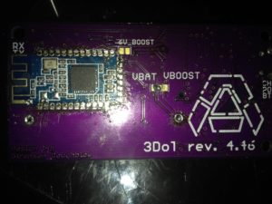
3dot-board-cut-min

The header was bypassed as shown in the picture above, and the output voltage with from the polyfuse on the 3DoT board to ground was 3.8-4.2V, consistent with the battery voltage.

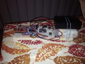
The 3Dot libraries are very useful for telecommunications between serial (Bluetooth) and the interfacing Arduino. The 3DoT board I would have like to test the libraries on was not fully functional, so I opted to recreate the dual motor driver on the 3DoT board using a L293D and a Pro Micro. For my testing I used the command handler for the MOVE command, which was used to decode the move signals and output a result to the motors. The move handler decodes the MOVE command to the three following values:

  • 0x00 – Stop the Motor
  • 0x01 – Drive the Motor in the forward direction
  • 0x02 – Drive the Motor in the reverse direction

From there, the PWM component of the signal is used as a direct drive to the motor in the 0-255 analogWrite format. The test setup is shown below.

breadboard-min

Coolterm was utilized to simulate Bluetooth serial commands coming into the Arduino. The following Commands were tested satisfactory from the handler.

  • A5 05 01 01 ff 01 ff A1 – A full Forward Drive of both motors
  • A5 05 01 01 ff 02 ff A2 – A Forward and Reverse offset of both motors
  • A5 05 01 00 ff 00 ff A1 – A full stop of both motors
  • A5 05 01 01 80 00 80 A0 – A stop of one motor and a half drive of the other motor

Implementation of this scheme will satisfy the project requirements for biped motion and static movement.

IMU Testing

MPU – 9150 Testing

Following the 3DoT library testing, IMU testing was performed using code that was utilizing the HPU-6050 IMU and the wire interface. The IMU produces good results when the IMU is not stationary too long to cause drift due to sensor integration. This process is explained here. The IMU tested used 40% of the 32% of the Arduino’s program memory, so the portability between platforms should be easily established.

This testing accomplishes the requirements of the project for X,Y, and Z angles to the hundredth of a degree.

IMU and 3DoT Combined Testing

The combination testing of the 3DoT library and the IMU was not as successful as it would be desired. There appears to be a conflict between these two sets of code that do not allow them to be used together. Further testing needs to be done to see how to accomplish a fusion of these two sensors.

Source Code

3DoT Code

#include <Robot3DoTBoard.h>     // instantiated as Robot3DoT at end of class header


#include <EEPROM.h>

#include <Wire.h>               // I2C support

#include <Servo.h>


// Motor Variables


int Motor1F = 5;

int Motor1R = 10;

int Motor1PWM = A9;


int Motor2F = 19;

int Motor2R = 20;

int Motor2PWM = 6;


int Mot1State = 0;

int Mot2State = 0;


// Servo Variables


//


Robot3DoTBoard Robot3DoT;       // instantiated as Robot3DoT at end of class header


/*

* Command Example

* Step 1: Assign new command mnemonics ID numbers

*         In our example we will be adding 3 custom commands (2 new and one predefined).

*         The predefined MOVE command is intercepted and our robot unique code is to be

*         run instead. The MOVE command mnemonic ID 0x01 is already defined in Configure.h

*         The next two commands are new and assigned to the first two addresses in the

*         custom command address space 0x40 – 0x5F.

*/


#define DYNSTAT       0x41

const uint8_t CMD_LIST_SIZE = 2;   // we are adding 3 commands (MOVE, BLINK, SERVO)


/*

* Command Example

* Step 2: Register commands by linking IDs to their corresponding command handlers

*         In our example when the MOVE command is intercepted the moveHandler is to be run.

*         In a similar fashion the BLINK command calls the blinkHandler and SERVO the

*         servoHandler.

*/


void moveHandler (uint8_t cmd, uint8_t param[], uint8_t n);

void dynstatHandler (uint8_t cmd, uint8_t param[], uint8_t n);


Robot3DoTBoard::cmdFunc_t onCommand[CMD_LIST_SIZE] = {{MOVE,moveHandler}, {DYNSTAT,dynstatHandler}};


/*

* Telemetry Example

* Step 1: Instantiate packet

*         In our example we simulate a current sensor wired to MOTOR 2. MOTOR2_CURRENT_ID

*         is defined as 0x02 in Configure.h

*         To simulate the data stream coming from the sensor we will read ATmega32U4

*         Register OCR4D which controls the duty cycle of MOTOR 2.

*/

Packet motorPWM(MOTOR2_CURRENT_ID);  // initialize the packet properties to default values


void setup()

{

Serial.begin(19200);               // default = 115200

Robot3DoT.begin();


// Initialize Motor To Off


pinMode(Motor1F, OUTPUT);

pinMode(Motor1R, OUTPUT);

pinMode(Motor1PWM, OUTPUT);


pinMode(Motor2F, OUTPUT);

pinMode(Motor2R, OUTPUT);

pinMode(Motor2PWM, OUTPUT);


digitalWrite(Motor1F,LOW);

digitalWrite(Motor1R,LOW);


digitalWrite(Motor2F,LOW);

digitalWrite(Motor2R,LOW);

Robot3DoT.setOnCommand(onCommand, CMD_LIST_SIZE);


/* Telemetry Example

* Step 2: Modify default values assigned to internal properties as needed.

*         Before a packet is created and sent, it is qualified. Specifically,

*         the data in a packet must change by some amount from the previous

*         packet and may not be sent with at a period less than some value.

*         In most cases you can leave these values at their default values.

*/


}

void loop()

{

Robot3DoT.loop();


// Set Motor State to the Telemetry Read Value


if (Mot1State == 1){ digitalWrite(Motor1F,HIGH);

digitalWrite(Motor1R,LOW);

} else if (Mot1State == 2) { digitalWrite(Motor1F,LOW);

digitalWrite(Motor1R,HIGH);

}                                 else {digitalWrite(Motor1F,LOW);

digitalWrite(Motor1R,LOW);}


if (Mot2State == 1){  digitalWrite(Motor2F,HIGH);

digitalWrite(Motor2R,LOW);

} else if (Mot2State == 2) { digitalWrite(Motor2F,LOW);

digitalWrite(Motor2R,HIGH);

}                                 else {digitalWrite(Motor2F,LOW);

digitalWrite(Motor2R,LOW);}


// Read IMU Settings


// Set Servos to IMU Setting


}


/*

* Command Example

* Step 4: Write command handlers

*/


/*

* User Defined Command BLINK (0x40) Example

* A5 01 40 E4

*/


/*

* Override MOVE (0x01) Command Example

* A5 05 01 01 80 01 80 A1

*/

void moveHandler (uint8_t cmd, uint8_t param[], uint8_t n)

{

Serial.write(cmd);             // move command = 0x01

Serial.write(n);               // number of param = 4

for (int i=0;i<n;i++)          // param = 01 80 01 80

{

Serial.write (param[i]);

}


Mot1State = param[0];

Mot2State = param[2];


// Configure Inputs and Outputs


if (param[0] == 1){ digitalWrite(Motor1F,HIGH);

digitalWrite(Motor1R,LOW);

Serial.println(“Left Leg Forward”);

} else if (param[0] == 2) { digitalWrite(Motor1F,LOW);

digitalWrite(Motor1R,HIGH);

Serial.println(“Left Leg Backwards”);

}                                 else {digitalWrite(Motor1F,LOW);

digitalWrite(Motor1R,LOW);

Serial.println(“Left Leg Stop”);}


if (param[2] == 1){  digitalWrite(Motor2F,HIGH);

digitalWrite(Motor2R,LOW);

Serial.println(“Right Leg Forward”);

} else if (param[2] == 2) { digitalWrite(Motor2F,LOW);

digitalWrite(Motor2R,HIGH);

Serial.println(“Right Leg Backwards”);

}                                 else {digitalWrite(Motor2F,LOW);

digitalWrite(Motor2R,LOW);

Serial.println(“Right Leg Stop”);}


analogWrite(Motor1PWM,param[1]);

analogWrite(Motor2PWM,param[3]);


}                                // moveHandler


/*

* User Defined Command SERVO (0x41) Example

* Rotate servo to 90 degrees

* A5 02 41 90 76

*/

void dynstatHandler (uint8_t cmd, uint8_t param[], uint8_t n)

{

Serial.write(cmd);             // servo command = 0x41

Serial.write(n);               // number of param = 1

for (int i=0;i<n;i++)          // param = 90 degrees

{

Serial.write (param[i]);

}


}  // servoHandler

Telemetry and Custom Command Source Code

/*

* Telemetry and Custom Command Sample Arduino Code

*   Telemetry Example: Monitor an extended I/O register value and send to control panel display

*   Command Example:   Add Robot unique MOVE, BLINK, and SERVO commands

*/


#include <Robot3DoTBoard.h>     // instantiated as Robot3DoT at end of class header


#include <EEPROM.h>

#include <Wire.h>               // I2C support

#include <Servo.h>


// IMU Variables


long HoldTime = micros();


#define MPU6050_AUX_VDDIO          0x01   // R/W

#define MPU6050_SMPLRT_DIV         0x19   // R/W

#define MPU6050_CONFIG             0x1A   // R/W

#define MPU6050_GYRO_CONFIG        0x1B   // R/W

#define MPU6050_ACCEL_CONFIG       0x1C   // R/W

#define MPU6050_FF_THR             0x1D   // R/W

#define MPU6050_FF_DUR             0x1E   // R/W

#define MPU6050_MOT_THR            0x1F   // R/W

#define MPU6050_MOT_DUR            0x20   // R/W

#define MPU6050_ZRMOT_THR          0x21   // R/W

#define MPU6050_ZRMOT_DUR          0x22   // R/W

#define MPU6050_FIFO_EN            0x23   // R/W

#define MPU6050_I2C_MST_CTRL       0x24   // R/W

#define MPU6050_I2C_SLV0_ADDR      0x25   // R/W

#define MPU6050_I2C_SLV0_REG       0x26   // R/W

#define MPU6050_I2C_SLV0_CTRL      0x27   // R/W

#define MPU6050_I2C_SLV1_ADDR      0x28   // R/W

#define MPU6050_I2C_SLV1_REG       0x29   // R/W

#define MPU6050_I2C_SLV1_CTRL      0x2A   // R/W

#define MPU6050_I2C_SLV2_ADDR      0x2B   // R/W

#define MPU6050_I2C_SLV2_REG       0x2C   // R/W

#define MPU6050_I2C_SLV2_CTRL      0x2D   // R/W

#define MPU6050_I2C_SLV3_ADDR      0x2E   // R/W

#define MPU6050_I2C_SLV3_REG       0x2F   // R/W

#define MPU6050_I2C_SLV3_CTRL      0x30   // R/W

#define MPU6050_I2C_SLV4_ADDR      0x31   // R/W

#define MPU6050_I2C_SLV4_REG       0x32   // R/W

#define MPU6050_I2C_SLV4_DO        0x33   // R/W

#define MPU6050_I2C_SLV4_CTRL      0x34   // R/W

#define MPU6050_I2C_SLV4_DI        0x35   // R

#define MPU6050_I2C_MST_STATUS     0x36   // R

#define MPU6050_INT_PIN_CFG        0x37   // R/W

#define MPU6050_INT_ENABLE         0x38   // R/W

#define MPU6050_INT_STATUS         0x3A   // R

#define MPU6050_ACCEL_XOUT_H       0x3B   // R

#define MPU6050_ACCEL_XOUT_L       0x3C   // R

#define MPU6050_ACCEL_YOUT_H       0x3D   // R

#define MPU6050_ACCEL_YOUT_L       0x3E   // R

#define MPU6050_ACCEL_ZOUT_H       0x3F   // R

#define MPU6050_ACCEL_ZOUT_L       0x40   // R

#define MPU6050_TEMP_OUT_H         0x41   // R

#define MPU6050_TEMP_OUT_L         0x42   // R

#define MPU6050_GYRO_XOUT_H        0x43   // R

#define MPU6050_GYRO_XOUT_L        0x44   // R

#define MPU6050_GYRO_YOUT_H        0x45   // R

#define MPU6050_GYRO_YOUT_L        0x46   // R

#define MPU6050_GYRO_ZOUT_H        0x47   // R

#define MPU6050_GYRO_ZOUT_L        0x48   // R

#define MPU6050_EXT_SENS_DATA_00   0x49   // R

#define MPU6050_EXT_SENS_DATA_01   0x4A   // R

#define MPU6050_EXT_SENS_DATA_02   0x4B   // R

#define MPU6050_EXT_SENS_DATA_03   0x4C   // R

#define MPU6050_EXT_SENS_DATA_04   0x4D   // R

#define MPU6050_EXT_SENS_DATA_05   0x4E   // R

#define MPU6050_EXT_SENS_DATA_06   0x4F   // R

#define MPU6050_EXT_SENS_DATA_07   0x50   // R

#define MPU6050_EXT_SENS_DATA_08   0x51   // R

#define MPU6050_EXT_SENS_DATA_09   0x52   // R

#define MPU6050_EXT_SENS_DATA_10   0x53   // R

#define MPU6050_EXT_SENS_DATA_11   0x54   // R

#define MPU6050_EXT_SENS_DATA_12   0x55   // R

#define MPU6050_EXT_SENS_DATA_13   0x56   // R

#define MPU6050_EXT_SENS_DATA_14   0x57   // R

#define MPU6050_EXT_SENS_DATA_15   0x58   // R

#define MPU6050_EXT_SENS_DATA_16   0x59   // R

#define MPU6050_EXT_SENS_DATA_17   0x5A   // R

#define MPU6050_EXT_SENS_DATA_18   0x5B   // R

#define MPU6050_EXT_SENS_DATA_19   0x5C   // R

#define MPU6050_EXT_SENS_DATA_20   0x5D   // R

#define MPU6050_EXT_SENS_DATA_21   0x5E   // R

#define MPU6050_EXT_SENS_DATA_22   0x5F   // R

#define MPU6050_EXT_SENS_DATA_23   0x60   // R

#define MPU6050_MOT_DETECT_STATUS  0x61   // R

#define MPU6050_I2C_SLV0_DO        0x63   // R/W

#define MPU6050_I2C_SLV1_DO        0x64   // R/W

#define MPU6050_I2C_SLV2_DO        0x65   // R/W

#define MPU6050_I2C_SLV3_DO        0x66   // R/W

#define MPU6050_I2C_MST_DELAY_CTRL 0x67   // R/W

#define MPU6050_SIGNAL_PATH_RESET  0x68   // R/W

#define MPU6050_MOT_DETECT_CTRL    0x69   // R/W

#define MPU6050_USER_CTRL          0x6A   // R/W

#define MPU6050_PWR_MGMT_1         0x6B   // R/W

#define MPU6050_PWR_MGMT_2         0x6C   // R/W

#define MPU6050_FIFO_COUNTH        0x72   // R/W

#define MPU6050_FIFO_COUNTL        0x73   // R/W

#define MPU6050_FIFO_R_W           0x74   // R/W

#define MPU6050_WHO_AM_I           0x75   // R


// Defines for the bits, to be able to change

// between bit number and binary definition.

// By using the bit number, programming the sensor

// is like programming the AVR microcontroller.

// But instead of using “(1<<X)”, or “_BV(X)”,

// the Arduino “bit(X)” is used.

#define MPU6050_D0 0

#define MPU6050_D1 1

#define MPU6050_D2 2

#define MPU6050_D3 3

#define MPU6050_D4 4

#define MPU6050_D5 5

#define MPU6050_D6 6

#define MPU6050_D7 7


// AUX_VDDIO Register

#define MPU6050_AUX_VDDIO MPU6050_D7  // I2C high: 1=VDD, 0=VLOGIC


// CONFIG Register

// DLPF is Digital Low Pass Filter for both gyro and accelerometers.

// These are the names for the bits.

// Use these only with the bit() macro.

#define MPU6050_DLPF_CFG0     MPU6050_D0

#define MPU6050_DLPF_CFG1     MPU6050_D1

#define MPU6050_DLPF_CFG2     MPU6050_D2

#define MPU6050_EXT_SYNC_SET0 MPU6050_D3

#define MPU6050_EXT_SYNC_SET1 MPU6050_D4

#define MPU6050_EXT_SYNC_SET2 MPU6050_D5


// Combined definitions for the EXT_SYNC_SET values

#define MPU6050_EXT_SYNC_SET_0 (0)

#define MPU6050_EXT_SYNC_SET_1 (bit(MPU6050_EXT_SYNC_SET0))

#define MPU6050_EXT_SYNC_SET_2 (bit(MPU6050_EXT_SYNC_SET1))

#define MPU6050_EXT_SYNC_SET_3 (bit(MPU6050_EXT_SYNC_SET1)|bit(MPU6050_EXT_SYNC_SET0))

#define MPU6050_EXT_SYNC_SET_4 (bit(MPU6050_EXT_SYNC_SET2))

#define MPU6050_EXT_SYNC_SET_5 (bit(MPU6050_EXT_SYNC_SET2)|bit(MPU6050_EXT_SYNC_SET0))

#define MPU6050_EXT_SYNC_SET_6 (bit(MPU6050_EXT_SYNC_SET2)|bit(MPU6050_EXT_SYNC_SET1))

#define MPU6050_EXT_SYNC_SET_7 (bit(MPU6050_EXT_SYNC_SET2)|bit(MPU6050_EXT_SYNC_SET1)|bit(MPU6050_EXT_SYNC_SET0))


// Alternative names for the combined definitions.

#define MPU6050_EXT_SYNC_DISABLED     MPU6050_EXT_SYNC_SET_0

#define MPU6050_EXT_SYNC_TEMP_OUT_L   MPU6050_EXT_SYNC_SET_1

#define MPU6050_EXT_SYNC_GYRO_XOUT_L  MPU6050_EXT_SYNC_SET_2

#define MPU6050_EXT_SYNC_GYRO_YOUT_L  MPU6050_EXT_SYNC_SET_3

#define MPU6050_EXT_SYNC_GYRO_ZOUT_L  MPU6050_EXT_SYNC_SET_4

#define MPU6050_EXT_SYNC_ACCEL_XOUT_L MPU6050_EXT_SYNC_SET_5

#define MPU6050_EXT_SYNC_ACCEL_YOUT_L MPU6050_EXT_SYNC_SET_6

#define MPU6050_EXT_SYNC_ACCEL_ZOUT_L MPU6050_EXT_SYNC_SET_7


// Combined definitions for the DLPF_CFG values

#define MPU6050_DLPF_CFG_0 (0)

#define MPU6050_DLPF_CFG_1 (bit(MPU6050_DLPF_CFG0))

#define MPU6050_DLPF_CFG_2 (bit(MPU6050_DLPF_CFG1))

#define MPU6050_DLPF_CFG_3 (bit(MPU6050_DLPF_CFG1)|bit(MPU6050_DLPF_CFG0))

#define MPU6050_DLPF_CFG_4 (bit(MPU6050_DLPF_CFG2))

#define MPU6050_DLPF_CFG_5 (bit(MPU6050_DLPF_CFG2)|bit(MPU6050_DLPF_CFG0))

#define MPU6050_DLPF_CFG_6 (bit(MPU6050_DLPF_CFG2)|bit(MPU6050_DLPF_CFG1))

#define MPU6050_DLPF_CFG_7 (bit(MPU6050_DLPF_CFG2)|bit(MPU6050_DLPF_CFG1)|bit(MPU6050_DLPF_CFG0))


// Alternative names for the combined definitions

// This name uses the bandwidth (Hz) for the accelometer,

// for the gyro the bandwidth is almost the same.

#define MPU6050_DLPF_260HZ    MPU6050_DLPF_CFG_0

#define MPU6050_DLPF_184HZ    MPU6050_DLPF_CFG_1

#define MPU6050_DLPF_94HZ     MPU6050_DLPF_CFG_2

#define MPU6050_DLPF_44HZ     MPU6050_DLPF_CFG_3

#define MPU6050_DLPF_21HZ     MPU6050_DLPF_CFG_4

#define MPU6050_DLPF_10HZ     MPU6050_DLPF_CFG_5

#define MPU6050_DLPF_5HZ      MPU6050_DLPF_CFG_6

#define MPU6050_DLPF_RESERVED MPU6050_DLPF_CFG_7


// GYRO_CONFIG Register

// The XG_ST, YG_ST, ZG_ST are bits for selftest.

// The FS_SEL sets the range for the gyro.

// These are the names for the bits.

// Use these only with the bit() macro.

#define MPU6050_FS_SEL0 MPU6050_D3

#define MPU6050_FS_SEL1 MPU6050_D4

#define MPU6050_ZG_ST   MPU6050_D5

#define MPU6050_YG_ST   MPU6050_D6

#define MPU6050_XG_ST   MPU6050_D7


// Combined definitions for the FS_SEL values

#define MPU6050_FS_SEL_0 (0)

#define MPU6050_FS_SEL_1 (bit(MPU6050_FS_SEL0))

#define MPU6050_FS_SEL_2 (bit(MPU6050_FS_SEL1))

#define MPU6050_FS_SEL_3 (bit(MPU6050_FS_SEL1)|bit(MPU6050_FS_SEL0))


// Alternative names for the combined definitions

// The name uses the range in degrees per second.

#define MPU6050_FS_SEL_250  MPU6050_FS_SEL_0

#define MPU6050_FS_SEL_500  MPU6050_FS_SEL_1

#define MPU6050_FS_SEL_1000 MPU6050_FS_SEL_2

#define MPU6050_FS_SEL_2000 MPU6050_FS_SEL_3


// ACCEL_CONFIG Register

// The XA_ST, YA_ST, ZA_ST are bits for selftest.

// The AFS_SEL sets the range for the accelerometer.

// These are the names for the bits.

// Use these only with the bit() macro.

#define MPU6050_ACCEL_HPF0 MPU6050_D0

#define MPU6050_ACCEL_HPF1 MPU6050_D1

#define MPU6050_ACCEL_HPF2 MPU6050_D2

#define MPU6050_AFS_SEL0   MPU6050_D3

#define MPU6050_AFS_SEL1   MPU6050_D4

#define MPU6050_ZA_ST      MPU6050_D5

#define MPU6050_YA_ST      MPU6050_D6

#define MPU6050_XA_ST      MPU6050_D7


// Combined definitions for the ACCEL_HPF values

#define MPU6050_ACCEL_HPF_0 (0)

#define MPU6050_ACCEL_HPF_1 (bit(MPU6050_ACCEL_HPF0))

#define MPU6050_ACCEL_HPF_2 (bit(MPU6050_ACCEL_HPF1))

#define MPU6050_ACCEL_HPF_3 (bit(MPU6050_ACCEL_HPF1)|bit(MPU6050_ACCEL_HPF0))

#define MPU6050_ACCEL_HPF_4 (bit(MPU6050_ACCEL_HPF2))

#define MPU6050_ACCEL_HPF_7 (bit(MPU6050_ACCEL_HPF2)|bit(MPU6050_ACCEL_HPF1)|bit(MPU6050_ACCEL_HPF0))


// Alternative names for the combined definitions

// The name uses the Cut-off frequency.

#define MPU6050_ACCEL_HPF_RESET  MPU6050_ACCEL_HPF_0

#define MPU6050_ACCEL_HPF_5HZ    MPU6050_ACCEL_HPF_1

#define MPU6050_ACCEL_HPF_2_5HZ  MPU6050_ACCEL_HPF_2

#define MPU6050_ACCEL_HPF_1_25HZ MPU6050_ACCEL_HPF_3

#define MPU6050_ACCEL_HPF_0_63HZ MPU6050_ACCEL_HPF_4

#define MPU6050_ACCEL_HPF_HOLD   MPU6050_ACCEL_HPF_7


// Combined definitions for the AFS_SEL values

#define MPU6050_AFS_SEL_0 (0)

#define MPU6050_AFS_SEL_1 (bit(MPU6050_AFS_SEL0))

#define MPU6050_AFS_SEL_2 (bit(MPU6050_AFS_SEL1))

#define MPU6050_AFS_SEL_3 (bit(MPU6050_AFS_SEL1)|bit(MPU6050_AFS_SEL0))


// Alternative names for the combined definitions

// The name uses the full scale range for the accelerometer.

#define MPU6050_AFS_SEL_2G  MPU6050_AFS_SEL_0

#define MPU6050_AFS_SEL_4G  MPU6050_AFS_SEL_1

#define MPU6050_AFS_SEL_8G  MPU6050_AFS_SEL_2

#define MPU6050_AFS_SEL_16G MPU6050_AFS_SEL_3


// FIFO_EN Register

// These are the names for the bits.

// Use these only with the bit() macro.

#define MPU6050_SLV0_FIFO_EN  MPU6050_D0

#define MPU6050_SLV1_FIFO_EN  MPU6050_D1

#define MPU6050_SLV2_FIFO_EN  MPU6050_D2

#define MPU6050_ACCEL_FIFO_EN MPU6050_D3

#define MPU6050_ZG_FIFO_EN    MPU6050_D4

#define MPU6050_YG_FIFO_EN    MPU6050_D5

#define MPU6050_XG_FIFO_EN    MPU6050_D6

#define MPU6050_TEMP_FIFO_EN  MPU6050_D7


// I2C_MST_CTRL Register

// These are the names for the bits.

// Use these only with the bit() macro.

#define MPU6050_I2C_MST_CLK0  MPU6050_D0

#define MPU6050_I2C_MST_CLK1  MPU6050_D1

#define MPU6050_I2C_MST_CLK2  MPU6050_D2

#define MPU6050_I2C_MST_CLK3  MPU6050_D3

#define MPU6050_I2C_MST_P_NSR MPU6050_D4

#define MPU6050_SLV_3_FIFO_EN MPU6050_D5

#define MPU6050_WAIT_FOR_ES   MPU6050_D6

#define MPU6050_MULT_MST_EN   MPU6050_D7


// Combined definitions for the I2C_MST_CLK

#define MPU6050_I2C_MST_CLK_0 (0)

#define MPU6050_I2C_MST_CLK_1  (bit(MPU6050_I2C_MST_CLK0))

#define MPU6050_I2C_MST_CLK_2  (bit(MPU6050_I2C_MST_CLK1))

#define MPU6050_I2C_MST_CLK_3  (bit(MPU6050_I2C_MST_CLK1)|bit(MPU6050_I2C_MST_CLK0))

#define MPU6050_I2C_MST_CLK_4  (bit(MPU6050_I2C_MST_CLK2))

#define MPU6050_I2C_MST_CLK_5  (bit(MPU6050_I2C_MST_CLK2)|bit(MPU6050_I2C_MST_CLK0))

#define MPU6050_I2C_MST_CLK_6  (bit(MPU6050_I2C_MST_CLK2)|bit(MPU6050_I2C_MST_CLK1))

#define MPU6050_I2C_MST_CLK_7  (bit(MPU6050_I2C_MST_CLK2)|bit(MPU6050_I2C_MST_CLK1)|bit(MPU6050_I2C_MST_CLK0))

#define MPU6050_I2C_MST_CLK_8  (bit(MPU6050_I2C_MST_CLK3))

#define MPU6050_I2C_MST_CLK_9  (bit(MPU6050_I2C_MST_CLK3)|bit(MPU6050_I2C_MST_CLK0))

#define MPU6050_I2C_MST_CLK_10 (bit(MPU6050_I2C_MST_CLK3)|bit(MPU6050_I2C_MST_CLK1))

#define MPU6050_I2C_MST_CLK_11 (bit(MPU6050_I2C_MST_CLK3)|bit(MPU6050_I2C_MST_CLK1)|bit(MPU6050_I2C_MST_CLK0))

#define MPU6050_I2C_MST_CLK_12 (bit(MPU6050_I2C_MST_CLK3)|bit(MPU6050_I2C_MST_CLK2))

#define MPU6050_I2C_MST_CLK_13 (bit(MPU6050_I2C_MST_CLK3)|bit(MPU6050_I2C_MST_CLK2)|bit(MPU6050_I2C_MST_CLK0))

#define MPU6050_I2C_MST_CLK_14 (bit(MPU6050_I2C_MST_CLK3)|bit(MPU6050_I2C_MST_CLK2)|bit(MPU6050_I2C_MST_CLK1))

#define MPU6050_I2C_MST_CLK_15 (bit(MPU6050_I2C_MST_CLK3)|bit(MPU6050_I2C_MST_CLK2)|bit(MPU6050_I2C_MST_CLK1)|bit(MPU6050_I2C_MST_CLK0))


// Alternative names for the combined definitions

// The names uses I2C Master Clock Speed in kHz.

#define MPU6050_I2C_MST_CLK_348KHZ MPU6050_I2C_MST_CLK_0

#define MPU6050_I2C_MST_CLK_333KHZ MPU6050_I2C_MST_CLK_1

#define MPU6050_I2C_MST_CLK_320KHZ MPU6050_I2C_MST_CLK_2

#define MPU6050_I2C_MST_CLK_308KHZ MPU6050_I2C_MST_CLK_3

#define MPU6050_I2C_MST_CLK_296KHZ MPU6050_I2C_MST_CLK_4

#define MPU6050_I2C_MST_CLK_286KHZ MPU6050_I2C_MST_CLK_5

#define MPU6050_I2C_MST_CLK_276KHZ MPU6050_I2C_MST_CLK_6

#define MPU6050_I2C_MST_CLK_267KHZ MPU6050_I2C_MST_CLK_7

#define MPU6050_I2C_MST_CLK_258KHZ MPU6050_I2C_MST_CLK_8

#define MPU6050_I2C_MST_CLK_500KHZ MPU6050_I2C_MST_CLK_9

#define MPU6050_I2C_MST_CLK_471KHZ MPU6050_I2C_MST_CLK_10

#define MPU6050_I2C_MST_CLK_444KHZ MPU6050_I2C_MST_CLK_11

#define MPU6050_I2C_MST_CLK_421KHZ MPU6050_I2C_MST_CLK_12

#define MPU6050_I2C_MST_CLK_400KHZ MPU6050_I2C_MST_CLK_13

#define MPU6050_I2C_MST_CLK_381KHZ MPU6050_I2C_MST_CLK_14

#define MPU6050_I2C_MST_CLK_364KHZ MPU6050_I2C_MST_CLK_15


// I2C_SLV0_ADDR Register

// These are the names for the bits.

// Use these only with the bit() macro.

#define MPU6050_I2C_SLV0_RW MPU6050_D7


// I2C_SLV0_CTRL Register

// These are the names for the bits.

// Use these only with the bit() macro.

#define MPU6050_I2C_SLV0_LEN0    MPU6050_D0

#define MPU6050_I2C_SLV0_LEN1    MPU6050_D1

#define MPU6050_I2C_SLV0_LEN2    MPU6050_D2

#define MPU6050_I2C_SLV0_LEN3    MPU6050_D3

#define MPU6050_I2C_SLV0_GRP     MPU6050_D4

#define MPU6050_I2C_SLV0_REG_DIS MPU6050_D5

#define MPU6050_I2C_SLV0_BYTE_SW MPU6050_D6

#define MPU6050_I2C_SLV0_EN      MPU6050_D7


// A mask for the length

#define MPU6050_I2C_SLV0_LEN_MASK 0x0F


// I2C_SLV1_ADDR Register

// These are the names for the bits.

// Use these only with the bit() macro.

#define MPU6050_I2C_SLV1_RW MPU6050_D7


// I2C_SLV1_CTRL Register

// These are the names for the bits.

// Use these only with the bit() macro.

#define MPU6050_I2C_SLV1_LEN0    MPU6050_D0

#define MPU6050_I2C_SLV1_LEN1    MPU6050_D1

#define MPU6050_I2C_SLV1_LEN2    MPU6050_D2

#define MPU6050_I2C_SLV1_LEN3    MPU6050_D3

#define MPU6050_I2C_SLV1_GRP     MPU6050_D4

#define MPU6050_I2C_SLV1_REG_DIS MPU6050_D5

#define MPU6050_I2C_SLV1_BYTE_SW MPU6050_D6

#define MPU6050_I2C_SLV1_EN      MPU6050_D7


// A mask for the length

#define MPU6050_I2C_SLV1_LEN_MASK 0x0F


// I2C_SLV2_ADDR Register

// These are the names for the bits.

// Use these only with the bit() macro.

#define MPU6050_I2C_SLV2_RW MPU6050_D7


// I2C_SLV2_CTRL Register

// These are the names for the bits.

// Use these only with the bit() macro.

#define MPU6050_I2C_SLV2_LEN0    MPU6050_D0

#define MPU6050_I2C_SLV2_LEN1    MPU6050_D1

#define MPU6050_I2C_SLV2_LEN2    MPU6050_D2

#define MPU6050_I2C_SLV2_LEN3    MPU6050_D3

#define MPU6050_I2C_SLV2_GRP     MPU6050_D4

#define MPU6050_I2C_SLV2_REG_DIS MPU6050_D5

#define MPU6050_I2C_SLV2_BYTE_SW MPU6050_D6

#define MPU6050_I2C_SLV2_EN      MPU6050_D7


// A mask for the length

#define MPU6050_I2C_SLV2_LEN_MASK 0x0F


// I2C_SLV3_ADDR Register

// These are the names for the bits.

// Use these only with the bit() macro.

#define MPU6050_I2C_SLV3_RW MPU6050_D7


// I2C_SLV3_CTRL Register

// These are the names for the bits.

// Use these only with the bit() macro.

#define MPU6050_I2C_SLV3_LEN0    MPU6050_D0

#define MPU6050_I2C_SLV3_LEN1    MPU6050_D1

#define MPU6050_I2C_SLV3_LEN2    MPU6050_D2

#define MPU6050_I2C_SLV3_LEN3    MPU6050_D3

#define MPU6050_I2C_SLV3_GRP     MPU6050_D4

#define MPU6050_I2C_SLV3_REG_DIS MPU6050_D5

#define MPU6050_I2C_SLV3_BYTE_SW MPU6050_D6

#define MPU6050_I2C_SLV3_EN      MPU6050_D7


// A mask for the length

#define MPU6050_I2C_SLV3_LEN_MASK 0x0F


// I2C_SLV4_ADDR Register

// These are the names for the bits.

// Use these only with the bit() macro.

#define MPU6050_I2C_SLV4_RW MPU6050_D7


// I2C_SLV4_CTRL Register

// These are the names for the bits.

// Use these only with the bit() macro.

#define MPU6050_I2C_MST_DLY0     MPU6050_D0

#define MPU6050_I2C_MST_DLY1     MPU6050_D1

#define MPU6050_I2C_MST_DLY2     MPU6050_D2

#define MPU6050_I2C_MST_DLY3     MPU6050_D3

#define MPU6050_I2C_MST_DLY4     MPU6050_D4

#define MPU6050_I2C_SLV4_REG_DIS MPU6050_D5

#define MPU6050_I2C_SLV4_INT_EN  MPU6050_D6

#define MPU6050_I2C_SLV4_EN      MPU6050_D7


// A mask for the delay

#define MPU6050_I2C_MST_DLY_MASK 0x1F


// I2C_MST_STATUS Register

// These are the names for the bits.

// Use these only with the bit() macro.

#define MPU6050_I2C_SLV0_NACK MPU6050_D0

#define MPU6050_I2C_SLV1_NACK MPU6050_D1

#define MPU6050_I2C_SLV2_NACK MPU6050_D2

#define MPU6050_I2C_SLV3_NACK MPU6050_D3

#define MPU6050_I2C_SLV4_NACK MPU6050_D4

#define MPU6050_I2C_LOST_ARB  MPU6050_D5

#define MPU6050_I2C_SLV4_DONE MPU6050_D6

#define MPU6050_PASS_THROUGH  MPU6050_D7


// I2C_PIN_CFG Register

// These are the names for the bits.

// Use these only with the bit() macro.

#define MPU6050_CLKOUT_EN       MPU6050_D0

#define MPU6050_I2C_BYPASS_EN   MPU6050_D1

#define MPU6050_FSYNC_INT_EN    MPU6050_D2

#define MPU6050_FSYNC_INT_LEVEL MPU6050_D3

#define MPU6050_INT_RD_CLEAR    MPU6050_D4

#define MPU6050_LATCH_INT_EN    MPU6050_D5

#define MPU6050_INT_OPEN        MPU6050_D6

#define MPU6050_INT_LEVEL       MPU6050_D7


// INT_ENABLE Register

// These are the names for the bits.

// Use these only with the bit() macro.

#define MPU6050_DATA_RDY_EN    MPU6050_D0

#define MPU6050_I2C_MST_INT_EN MPU6050_D3

#define MPU6050_FIFO_OFLOW_EN  MPU6050_D4

#define MPU6050_ZMOT_EN        MPU6050_D5

#define MPU6050_MOT_EN         MPU6050_D6

#define MPU6050_FF_EN          MPU6050_D7


// INT_STATUS Register

// These are the names for the bits.

// Use these only with the bit() macro.

#define MPU6050_DATA_RDY_INT   MPU6050_D0

#define MPU6050_I2C_MST_INT    MPU6050_D3

#define MPU6050_FIFO_OFLOW_INT MPU6050_D4

#define MPU6050_ZMOT_INT       MPU6050_D5

#define MPU6050_MOT_INT        MPU6050_D6

#define MPU6050_FF_INT         MPU6050_D7


// MOT_DETECT_STATUS Register

// These are the names for the bits.

// Use these only with the bit() macro.

#define MPU6050_MOT_ZRMOT MPU6050_D0

#define MPU6050_MOT_ZPOS  MPU6050_D2

#define MPU6050_MOT_ZNEG  MPU6050_D3

#define MPU6050_MOT_YPOS  MPU6050_D4

#define MPU6050_MOT_YNEG  MPU6050_D5

#define MPU6050_MOT_XPOS  MPU6050_D6

#define MPU6050_MOT_XNEG  MPU6050_D7


// IC2_MST_DELAY_CTRL Register

// These are the names for the bits.

// Use these only with the bit() macro.

#define MPU6050_I2C_SLV0_DLY_EN MPU6050_D0

#define MPU6050_I2C_SLV1_DLY_EN MPU6050_D1

#define MPU6050_I2C_SLV2_DLY_EN MPU6050_D2

#define MPU6050_I2C_SLV3_DLY_EN MPU6050_D3

#define MPU6050_I2C_SLV4_DLY_EN MPU6050_D4

#define MPU6050_DELAY_ES_SHADOW MPU6050_D7


// SIGNAL_PATH_RESET Register

// These are the names for the bits.

// Use these only with the bit() macro.

#define MPU6050_TEMP_RESET  MPU6050_D0

#define MPU6050_ACCEL_RESET MPU6050_D1

#define MPU6050_GYRO_RESET  MPU6050_D2


// MOT_DETECT_CTRL Register

// These are the names for the bits.

// Use these only with the bit() macro.

#define MPU6050_MOT_COUNT0      MPU6050_D0

#define MPU6050_MOT_COUNT1      MPU6050_D1

#define MPU6050_FF_COUNT0       MPU6050_D2

#define MPU6050_FF_COUNT1       MPU6050_D3

#define MPU6050_ACCEL_ON_DELAY0 MPU6050_D4

#define MPU6050_ACCEL_ON_DELAY1 MPU6050_D5


// Combined definitions for the MOT_COUNT

#define MPU6050_MOT_COUNT_0 (0)

#define MPU6050_MOT_COUNT_1 (bit(MPU6050_MOT_COUNT0))

#define MPU6050_MOT_COUNT_2 (bit(MPU6050_MOT_COUNT1))

#define MPU6050_MOT_COUNT_3 (bit(MPU6050_MOT_COUNT1)|bit(MPU6050_MOT_COUNT0))


// Alternative names for the combined definitions

#define MPU6050_MOT_COUNT_RESET MPU6050_MOT_COUNT_0


// Combined definitions for the FF_COUNT

#define MPU6050_FF_COUNT_0 (0)

#define MPU6050_FF_COUNT_1 (bit(MPU6050_FF_COUNT0))

#define MPU6050_FF_COUNT_2 (bit(MPU6050_FF_COUNT1))

#define MPU6050_FF_COUNT_3 (bit(MPU6050_FF_COUNT1)|bit(MPU6050_FF_COUNT0))


// Alternative names for the combined definitions

#define MPU6050_FF_COUNT_RESET MPU6050_FF_COUNT_0


// Combined definitions for the ACCEL_ON_DELAY

#define MPU6050_ACCEL_ON_DELAY_0 (0)

#define MPU6050_ACCEL_ON_DELAY_1 (bit(MPU6050_ACCEL_ON_DELAY0))

#define MPU6050_ACCEL_ON_DELAY_2 (bit(MPU6050_ACCEL_ON_DELAY1))

#define MPU6050_ACCEL_ON_DELAY_3 (bit(MPU6050_ACCEL_ON_DELAY1)|bit(MPU6050_ACCEL_ON_DELAY0))


// Alternative names for the ACCEL_ON_DELAY

#define MPU6050_ACCEL_ON_DELAY_0MS MPU6050_ACCEL_ON_DELAY_0

#define MPU6050_ACCEL_ON_DELAY_1MS MPU6050_ACCEL_ON_DELAY_1

#define MPU6050_ACCEL_ON_DELAY_2MS MPU6050_ACCEL_ON_DELAY_2

#define MPU6050_ACCEL_ON_DELAY_3MS MPU6050_ACCEL_ON_DELAY_3


// USER_CTRL Register

// These are the names for the bits.

// Use these only with the bit() macro.

#define MPU6050_SIG_COND_RESET MPU6050_D0

#define MPU6050_I2C_MST_RESET  MPU6050_D1

#define MPU6050_FIFO_RESET     MPU6050_D2

#define MPU6050_I2C_IF_DIS     MPU6050_D4   // must be 0 for MPU-6050

#define MPU6050_I2C_MST_EN     MPU6050_D5

#define MPU6050_FIFO_EN        MPU6050_D6


// PWR_MGMT_1 Register

// These are the names for the bits.

// Use these only with the bit() macro.

#define MPU6050_CLKSEL0      MPU6050_D0

#define MPU6050_CLKSEL1      MPU6050_D1

#define MPU6050_CLKSEL2      MPU6050_D2

#define MPU6050_TEMP_DIS     MPU6050_D3    // 1: disable temperature sensor

#define MPU6050_CYCLE        MPU6050_D5    // 1: sample and sleep

#define MPU6050_SLEEP        MPU6050_D6    // 1: sleep mode

#define MPU6050_DEVICE_RESET MPU6050_D7    // 1: reset to default values


// Combined definitions for the CLKSEL

#define MPU6050_CLKSEL_0 (0)

#define MPU6050_CLKSEL_1 (bit(MPU6050_CLKSEL0))

#define MPU6050_CLKSEL_2 (bit(MPU6050_CLKSEL1))

#define MPU6050_CLKSEL_3 (bit(MPU6050_CLKSEL1)|bit(MPU6050_CLKSEL0))

#define MPU6050_CLKSEL_4 (bit(MPU6050_CLKSEL2))

#define MPU6050_CLKSEL_5 (bit(MPU6050_CLKSEL2)|bit(MPU6050_CLKSEL0))

#define MPU6050_CLKSEL_6 (bit(MPU6050_CLKSEL2)|bit(MPU6050_CLKSEL1))

#define MPU6050_CLKSEL_7 (bit(MPU6050_CLKSEL2)|bit(MPU6050_CLKSEL1)|bit(MPU6050_CLKSEL0))


// Alternative names for the combined definitions

#define MPU6050_CLKSEL_INTERNAL    MPU6050_CLKSEL_0

#define MPU6050_CLKSEL_X           MPU6050_CLKSEL_1

#define MPU6050_CLKSEL_Y           MPU6050_CLKSEL_2

#define MPU6050_CLKSEL_Z           MPU6050_CLKSEL_3

#define MPU6050_CLKSEL_EXT_32KHZ   MPU6050_CLKSEL_4

#define MPU6050_CLKSEL_EXT_19_2MHZ MPU6050_CLKSEL_5

#define MPU6050_CLKSEL_RESERVED    MPU6050_CLKSEL_6

#define MPU6050_CLKSEL_STOP        MPU6050_CLKSEL_7


// PWR_MGMT_2 Register

// These are the names for the bits.

// Use these only with the bit() macro.

#define MPU6050_STBY_ZG       MPU6050_D0

#define MPU6050_STBY_YG       MPU6050_D1

#define MPU6050_STBY_XG       MPU6050_D2

#define MPU6050_STBY_ZA       MPU6050_D3

#define MPU6050_STBY_YA       MPU6050_D4

#define MPU6050_STBY_XA       MPU6050_D5

#define MPU6050_LP_WAKE_CTRL0 MPU6050_D6

#define MPU6050_LP_WAKE_CTRL1 MPU6050_D7


// Combined definitions for the LP_WAKE_CTRL

#define MPU6050_LP_WAKE_CTRL_0 (0)

#define MPU6050_LP_WAKE_CTRL_1 (bit(MPU6050_LP_WAKE_CTRL0))

#define MPU6050_LP_WAKE_CTRL_2 (bit(MPU6050_LP_WAKE_CTRL1))

#define MPU6050_LP_WAKE_CTRL_3 (bit(MPU6050_LP_WAKE_CTRL1)|bit(MPU6050_LP_WAKE_CTRL0))


// Alternative names for the combined definitions

// The names uses the Wake-up Frequency.

#define MPU6050_LP_WAKE_1_25HZ MPU6050_LP_WAKE_CTRL_0

#define MPU6050_LP_WAKE_2_5HZ  MPU6050_LP_WAKE_CTRL_1

#define MPU6050_LP_WAKE_5HZ    MPU6050_LP_WAKE_CTRL_2

#define MPU6050_LP_WAKE_10HZ   MPU6050_LP_WAKE_CTRL_3


// Default I2C address for the MPU-6050 is 0x68.

// But only if the AD0 pin is low.

// Some sensor boards have AD0 high, and the

// I2C address thus becomes 0x69.

#define MPU6050_I2C_ADDRESS 0x68


// Declaring an union for the registers and the axis values.

// The byte order does not match the byte order of

// the compiler and AVR chip.

// The AVR chip (on the Arduino board) has the Low Byte

// at the lower address.

// But the MPU-6050 has a different order: High Byte at

// lower address, so that has to be corrected.

// The register part “reg” is only used internally,

// and are swapped in code.

typedef union accel_t_gyro_union

{

struct

{

uint8_t x_accel_h;

uint8_t x_accel_l;

uint8_t y_accel_h;

uint8_t y_accel_l;

uint8_t z_accel_h;

uint8_t z_accel_l;

uint8_t t_h;

uint8_t t_l;

uint8_t x_gyro_h;

uint8_t x_gyro_l;

uint8_t y_gyro_h;

uint8_t y_gyro_l;

uint8_t z_gyro_h;

uint8_t z_gyro_l;

} reg;

struct

{

int x_accel;

int y_accel;

int z_accel;

int temperature;

int x_gyro;

int y_gyro;

int z_gyro;

} value;

};


// Use the following global variables and access functions to help store the overall

// rotation angle of the sensor

unsigned long last_read_time;

float         last_x_angle;  // These are the filtered angles

float         last_y_angle;

float         last_z_angle;

float         last_gyro_x_angle;  // Store the gyro angles to compare drift

float         last_gyro_y_angle;

float         last_gyro_z_angle;


void set_last_read_angle_data(unsigned long time, float x, float y, float z, float x_gyro, float y_gyro, float z_gyro) {

last_read_time = time;

last_x_angle = x;

last_y_angle = y;

last_z_angle = z;

last_gyro_x_angle = x_gyro;

last_gyro_y_angle = y_gyro;

last_gyro_z_angle = z_gyro;

}


inline unsigned long get_last_time() {return last_read_time;}

inline float get_last_x_angle() {return last_x_angle;}

inline float get_last_y_angle() {return last_y_angle;}

inline float get_last_z_angle() {return last_z_angle;}

inline float get_last_gyro_x_angle() {return last_gyro_x_angle;}

inline float get_last_gyro_y_angle() {return last_gyro_y_angle;}

inline float get_last_gyro_z_angle() {return last_gyro_z_angle;}


//  Use the following global variables and access functions

//  to calibrate the acceleration sensor

float    base_x_accel;

float    base_y_accel;

float    base_z_accel;


float    base_x_gyro;

float    base_y_gyro;

float    base_z_gyro;


int read_gyro_accel_vals(uint8_t* accel_t_gyro_ptr) {

// Read the raw values.

// Read 14 bytes at once,

// containing acceleration, temperature and gyro.

// With the default settings of the MPU-6050,

// there is no filter enabled, and the values

// are not very stable.  Returns the error value


accel_t_gyro_union* accel_t_gyro = (accel_t_gyro_union *) accel_t_gyro_ptr;


int error = MPU6050_read (MPU6050_ACCEL_XOUT_H, (uint8_t *) accel_t_gyro, sizeof(*accel_t_gyro));


// Swap all high and low bytes.

// After this, the registers values are swapped,

// so the structure name like x_accel_l does no

// longer contain the lower byte.

uint8_t swap;

#define SWAP(x,y) swap = x; x = y; y = swap


SWAP ((*accel_t_gyro).reg.x_accel_h, (*accel_t_gyro).reg.x_accel_l);

SWAP ((*accel_t_gyro).reg.y_accel_h, (*accel_t_gyro).reg.y_accel_l);

SWAP ((*accel_t_gyro).reg.z_accel_h, (*accel_t_gyro).reg.z_accel_l);

SWAP ((*accel_t_gyro).reg.t_h, (*accel_t_gyro).reg.t_l);

SWAP ((*accel_t_gyro).reg.x_gyro_h, (*accel_t_gyro).reg.x_gyro_l);

SWAP ((*accel_t_gyro).reg.y_gyro_h, (*accel_t_gyro).reg.y_gyro_l);

SWAP ((*accel_t_gyro).reg.z_gyro_h, (*accel_t_gyro).reg.z_gyro_l);


return error;

}


void calibrate_sensors() {

int                   num_readings = 10;

float                 x_accel = 0;

float                 y_accel = 0;

float                 z_accel = 0;

float                 x_gyro = 0;

float                 y_gyro = 0;

float                 z_gyro = 0;

accel_t_gyro_union    accel_t_gyro;


//Serial.println(“Starting Calibration”);


// Discard the first set of values read from the IMU

read_gyro_accel_vals((uint8_t *) &accel_t_gyro);


// Read and average the raw values from the IMU

for (int i = 0; i < num_readings; i++) {

read_gyro_accel_vals((uint8_t *) &accel_t_gyro);

x_accel += accel_t_gyro.value.x_accel;

y_accel += accel_t_gyro.value.y_accel;

z_accel += accel_t_gyro.value.z_accel;

x_gyro += accel_t_gyro.value.x_gyro;

y_gyro += accel_t_gyro.value.y_gyro;

z_gyro += accel_t_gyro.value.z_gyro;

delay(100);

}

x_accel /= num_readings;

y_accel /= num_readings;

z_accel /= num_readings;

x_gyro /= num_readings;

y_gyro /= num_readings;

z_gyro /= num_readings;


// Store the raw calibration values globally

base_x_accel = x_accel;

base_y_accel = y_accel;

base_z_accel = z_accel;

base_x_gyro = x_gyro;

base_y_gyro = y_gyro;

base_z_gyro = z_gyro;


//Serial.println(“Finishing Calibration”);

}


// Motor Variables


int Motor1F = 5;

int Motor1R = 10;

int Motor1PWM = A9;

volatile int Motor1Speed = 0;


int Motor2F = 19;

int Motor2R = 20;

int Motor2PWM = 6;

volatile int Motor2Speed = 0;


volatile int Mot1State = 0;

volatile int Mot2State = 0;


// Servo Variables


//


Robot3DoTBoard Robot3DoT;       // instantiated as Robot3DoT at end of class header


/*

* Command Example

* Step 1: Assign new command mnemonics ID numbers

*         In our example we will be adding 3 custom commands (2 new and one predefined).

*         The predefined MOVE command is intercepted and our robot unique code is to be

*         run instead. The MOVE command mnemonic ID 0x01 is already defined in Configure.h

*         The next two commands are new and assigned to the first two addresses in the

*         custom command address space 0x40 – 0x5F.

*/


#define DYNSTAT       0x41

const uint8_t CMD_LIST_SIZE = 2;   // we are adding 3 commands (MOVE, BLINK, SERVO)


/*

* Command Example

* Step 2: Register commands by linking IDs to their corresponding command handlers

*         In our example when the MOVE command is intercepted the moveHandler is to be run.

*         In a similar fashion the BLINK command calls the blinkHandler and SERVO the

*         servoHandler.

*/


void moveHandler (uint8_t cmd, uint8_t param[], uint8_t n);

void dynstatHandler (uint8_t cmd, uint8_t param[], uint8_t n);


Robot3DoTBoard::cmdFunc_t onCommand[CMD_LIST_SIZE] = {{MOVE,moveHandler}, {DYNSTAT,dynstatHandler}};


/*

* Telemetry Example

* Step 1: Instantiate packet

*         In our example we simulate a current sensor wired to MOTOR 2. MOTOR2_CURRENT_ID

*         is defined as 0x02 in Configure.h

*         To simulate the data stream coming from the sensor we will read ATmega32U4

*         Register OCR4D which controls the duty cycle of MOTOR 2.

*/

Packet motorPWM(MOTOR2_CURRENT_ID);  // initialize the packet properties to default values


void setup()

{

Serial.begin(9600);               // default = 115200


Robot3DoT.begin();


// Initialize Motor To Off


pinMode(Motor1F, OUTPUT);

pinMode(Motor1R, OUTPUT);

pinMode(Motor1PWM, OUTPUT);


pinMode(Motor2F, OUTPUT);

pinMode(Motor2R, OUTPUT);

pinMode(Motor2PWM, OUTPUT);


digitalWrite(Motor1F,LOW);

digitalWrite(Motor1R,LOW);


digitalWrite(Motor2F,LOW);

digitalWrite(Motor2R,LOW);


// Initialize IMU


int error;

uint8_t c;


/*

Serial.println(F(“InvenSense MPU-6050”));

Serial.println(F(“June 2012”));

*/

// Initialize the ‘Wire’ class for the I2C-bus.

Wire.begin();


// default at power-up:

//    Gyro at 250 degrees second

//    Acceleration at 2g

//    Clock source at internal 8MHz

//    The device is in sleep mode.

//


error = MPU6050_read (MPU6050_WHO_AM_I, &c, 1);


/*

Serial.print(F(“WHO_AM_I : “));

Serial.print(c,HEX);

Serial.print(F(“, error = “));

Serial.println(error,DEC);

*/


// According to the datasheet, the ‘sleep’ bit

// should read a ‘1’. But I read a ‘0’.

// That bit has to be cleared, since the sensor

// is in sleep mode at power-up. Even if the

// bit reads ‘0’.

error = MPU6050_read (MPU6050_PWR_MGMT_2, &c, 1);


/*

Serial.print(F(“PWR_MGMT_2 : “));

Serial.print(c,HEX);

Serial.print(F(“, error = “));

Serial.println(error,DEC);

*/


// Clear the ‘sleep’ bit to start the sensor.

MPU6050_write_reg (MPU6050_PWR_MGMT_1, 0);


//Initialize the angles

calibrate_sensors();


set_last_read_angle_data(millis(), 0, 0, 0, 0, 0, 0);


/*

* Command Example

* Step 3: Tell 3DoT Robot software about new commands

*

*

*/


Robot3DoT.setOnCommand(onCommand, CMD_LIST_SIZE);


/* Telemetry Example

* Step 2: Modify default values assigned to internal properties as needed.

*         Before a packet is created and sent, it is qualified. Specifically,

*         the data in a packet must change by some amount from the previous

*         packet and may not be sent with at a period less than some value.

*         In most cases you can leave these values at their default values.

*/

delay(1000);

}


void loop()

{

Robot3DoT.loop();

// Set Motor State to the Telemetry Read Value


if (Mot1State == 1){ digitalWrite(Motor1F,HIGH);

digitalWrite(Motor1R,LOW);

} else if (Mot1State == 2) { digitalWrite(Motor1F,LOW);

digitalWrite(Motor1R,HIGH);

}                                 else {digitalWrite(Motor1F,LOW);

digitalWrite(Motor1R,LOW);}


if (Mot2State == 1){  digitalWrite(Motor2F,HIGH);

digitalWrite(Motor2R,LOW);

} else if (Mot2State == 2) { digitalWrite(Motor2F,LOW);

digitalWrite(Motor2R,HIGH);

}                                 else {digitalWrite(Motor2F,LOW);

digitalWrite(Motor2R,LOW);}


analogWrite(Motor1PWM, Motor1Speed);

analogWrite(Motor2PWM, Motor2Speed);

if (micros() – HoldTime > 500000){

HoldTime = micros();

Serial.write(“”);

Serial.write(Mot1State);

Serial.write(Motor1Speed);

Serial.write(Mot2State);

Serial.write(Motor2Speed);

Serial.write(“”);

}

// Read IMU Settings


//IMU();


// Set Servos to IMU Setting


}


/*

* Command Example

* Step 4: Write command handlers

*/


/*

* User Defined Command BLINK (0x40) Example

* A5 01 40 E4

*/


/*

* Override MOVE (0x01) Command Example

* A5 05 01 01 80 01 80 A1

*/

void moveHandler (uint8_t cmd, uint8_t param[], uint8_t n)

{

Mot1State = param[0];

Mot2State = param[2];


// Configure Inputs and Output


Motor1Speed = param[1];

Motor2Speed = param[3];

Serial.write(cmd);             // move command = 0x01

Serial.write(n);               // number of param = 4

for (int i=0;i<n;i++)          // param = 01 80 01 80

{

Serial.write (param[i]);

}


}                                // moveHandler


/*

* User Defined Command SERVO (0x41) Example

* Rotate servo to 90 degrees

* A5 02 41 90 76

*/

void dynstatHandler (uint8_t cmd, uint8_t param[], uint8_t n)

{

Serial.write(cmd);             // servo command = 0x41

Serial.write(n);               // number of param = 1

for (int i=0;i<n;i++)          // param = 90 degrees

{

Serial.write (param[i]);

}


}  // servoHandler


// IMU LOOPS


void IMU()

{

int error;

double dT;

accel_t_gyro_union accel_t_gyro;


Serial.println(F(“”));

Serial.println(F(“MPU-6050”));


// Read the raw values.

cli();

error = read_gyro_accel_vals((uint8_t*) &accel_t_gyro);

sei();

// Get the time of reading for rotation computations

unsigned long t_now = millis();


Serial.print(F(“Read accel, temp and gyro, error = “));

Serial.println(error,DEC);


// Print the raw acceleration values

Serial.print(F(“accel x,y,z: “));

Serial.print(accel_t_gyro.value.x_accel, DEC);

Serial.print(F(“, “));

Serial.print(accel_t_gyro.value.y_accel, DEC);

Serial.print(F(“, “));

Serial.print(accel_t_gyro.value.z_accel, DEC);

Serial.println(F(“”));


// The temperature sensor is -40 to +85 degrees Celsius.

// It is a signed integer.

// According to the datasheet:

//   340 per degrees Celsius, -512 at 35 degrees.

// At 0 degrees: -512 – (340 * 35) = -12412

/*

Serial.print(F(“temperature: “));

dT = ( (double) accel_t_gyro.value.temperature + 12412.0) / 340.0;

Serial.print(dT, 3);

Serial.print(F(” degrees Celsius”));

Serial.println(F(“”));


// Print the raw gyro values.

Serial.print(F(“raw gyro x,y,z : “));

Serial.print(accel_t_gyro.value.x_gyro, DEC);

Serial.print(F(“, “));

Serial.print(accel_t_gyro.value.y_gyro, DEC);

Serial.print(F(“, “));

Serial.print(accel_t_gyro.value.z_gyro, DEC);

Serial.print(F(“, “));

Serial.println(F(“”));

*/


// Convert gyro values to degrees/sec

float FS_SEL = 131;

/*

float gyro_x = (accel_t_gyro.value.x_gyro – base_x_gyro)/FS_SEL;

float gyro_y = (accel_t_gyro.value.y_gyro – base_y_gyro)/FS_SEL;

float gyro_z = (accel_t_gyro.value.z_gyro – base_z_gyro)/FS_SEL;

*/

float gyro_x = (accel_t_gyro.value.x_gyro – base_x_gyro)/FS_SEL;

float gyro_y = (accel_t_gyro.value.y_gyro – base_y_gyro)/FS_SEL;

float gyro_z = (accel_t_gyro.value.z_gyro – base_z_gyro)/FS_SEL;


// Get raw acceleration values

//float G_CONVERT = 16384;

float accel_x = accel_t_gyro.value.x_accel;

float accel_y = accel_t_gyro.value.y_accel;

float accel_z = accel_t_gyro.value.z_accel;


// Get angle values from accelerometer

float RADIANS_TO_DEGREES = 180/3.14159;

//  float accel_vector_length = sqrt(pow(accel_x,2) + pow(accel_y,2) + pow(accel_z,2));

float accel_angle_y = atan(-1*accel_x/sqrt(pow(accel_y,2) + pow(accel_z,2)))*RADIANS_TO_DEGREES;

float accel_angle_x = atan(accel_y/sqrt(pow(accel_x,2) + pow(accel_z,2)))*RADIANS_TO_DEGREES;


float accel_angle_z = 0;


// Compute the (filtered) gyro angles

float dt =(t_now – get_last_time())/1000.0;

float gyro_angle_x = gyro_x*dt + get_last_x_angle();

float gyro_angle_y = gyro_y*dt + get_last_y_angle();

float gyro_angle_z = gyro_z*dt + get_last_z_angle();


// Compute the drifting gyro angles

float unfiltered_gyro_angle_x = gyro_x*dt + get_last_gyro_x_angle();

float unfiltered_gyro_angle_y = gyro_y*dt + get_last_gyro_y_angle();

float unfiltered_gyro_angle_z = gyro_z*dt + get_last_gyro_z_angle();


// Apply the complementary filter to figure out the change in angle – choice of alpha is

// estimated now.  Alpha depends on the sampling rate…

float alpha = 0.96;

float angle_x = alpha*gyro_angle_x + (1.0 – alpha)*accel_angle_x;

float angle_y = alpha*gyro_angle_y + (1.0 – alpha)*accel_angle_y;

float angle_z = gyro_angle_z;  //Accelerometer doesn’t give z-angle


// Update the saved data with the latest values

cli();

set_last_read_angle_data(t_now, angle_x, angle_y, angle_z, unfiltered_gyro_angle_x, unfiltered_gyro_angle_y, unfiltered_gyro_angle_z);

sei();

//  Send the data to the serial port

//  Serial.print(F(“DEL:”));              //Delta T

//  Serial.print(dt, DEC);

//  Serial.print(F(“#ACC:”));              //Accelerometer angle

//  Serial.print(accel_angle_x, 2);

//  Serial.print(F(“,”));

//  Serial.print(accel_angle_y, 2);

//  Serial.print(F(“,”));

//  Serial.print(accel_angle_z, 2);

//  Serial.print(F(“#GYR:”));

//  Serial.print(unfiltered_gyro_angle_x, 2);        //Gyroscope angle

//  Serial.print(F(“,”));

//  Serial.print(unfiltered_gyro_angle_y, 2);

//  Serial.print(F(“,”));

//  Serial.print(unfiltered_gyro_angle_z, 2);


//  Serial.print(F(“#FIL:”));             //Filtered angle

//  Serial.print(angle_x, 2);

//  Serial.print(F(“,”));

//  Serial.print(angle_y, 2);

//  Serial.print(F(“,”));

//  Serial.print(angle_z, 2);

//  Serial.println(F(“”));


}


// ——————————————————–

// MPU6050_read

//

// This is a common function to read multiple bytes

// from an I2C device.

//

// It uses the boolean parameter for Wire.endTransMission()

// to be able to hold or release the I2C-bus.

// This is implemented in Arduino 1.0.1.

//

// Only this function is used to read.

// There is no function for a single byte.

//

int MPU6050_read(int start, uint8_t *buffer, int size)

{

int i, n, error;


Wire.beginTransmission(MPU6050_I2C_ADDRESS);

n = Wire.write(start);

if (n != 1)

return (-10);


n = Wire.endTransmission(false);    // hold the I2C-bus

if (n != 0)

return (n);


// Third parameter is true: relase I2C-bus after data is read.

Wire.requestFrom(MPU6050_I2C_ADDRESS, size, true);

i = 0;

while(Wire.available() && i<size)

{

buffer[i++]=Wire.read();

}

if ( i != size)

return (-11);


return (0);  // return : no error

}


// ——————————————————–

// MPU6050_write

//

// This is a common function to write multiple bytes to an I2C device.

//

// If only a single register is written,

// use the function MPU_6050_write_reg().

//

// Parameters:

//   start : Start address, use a define for the register

//   pData : A pointer to the data to write.

//   size  : The number of bytes to write.

//

// If only a single register is written, a pointer

// to the data has to be used, and the size is

// a single byte:

//   int data = 0;        // the data to write

//   MPU6050_write (MPU6050_PWR_MGMT_1, &c, 1);

//

int MPU6050_write(int start, const uint8_t *pData, int size)

{

int n, error;


Wire.beginTransmission(MPU6050_I2C_ADDRESS);

n = Wire.write(start);        // write the start address

if (n != 1)

return (-20);


n = Wire.write(pData, size);  // write data bytes

if (n != size)

return (-21);


error = Wire.endTransmission(true); // release the I2C-bus

if (error != 0)

return (error);


return (0);         // return : no error

}


// ——————————————————–

// MPU6050_write_reg

//

// An extra function to write a single register.

// It is just a wrapper around the MPU_6050_write()

// function, and it is only a convenient function

// to make it easier to write a single register.

//

int MPU6050_write_reg(int reg, uint8_t data)

{

int error;


error = MPU6050_write(reg, &data, 1);


return (error);

}