By: Nick Lukin (Design and Manufacturing Engineer)
Table of Contents
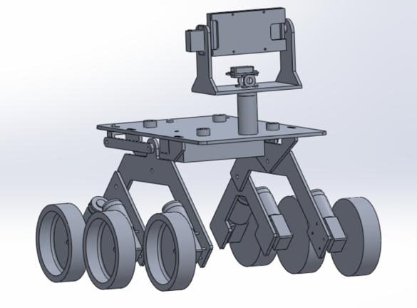
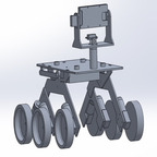
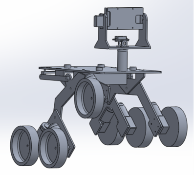
Figure 1: Overall Mechanical Design
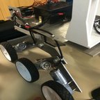
The mechanical design of the Pathfinder utilizes many parts and sub-assemblies in order to achieve all the requirements associated with the overall design. In order to achieve the level 1 requirement of being able to successfully traverse a pre-determined course on campus it was necessary to utilize a proper suspension system. It was also necessary to completely rebuild the pan and tilt smart phone holder in order to fit a Samsung Galaxy S7 edge. The suspension design utilizes a rocker bogie suspension system very similar to the one used on the Spirit rover. Below is a description of the overall mechanical design including all of its assemblies and sub-assemblies.

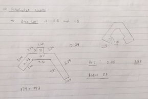
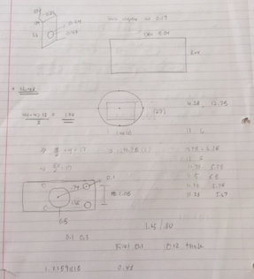
The Spring 2016 Pathfinder was used as a base reference in order to come up with a usable overall design. Each part was measured and then modeled in solidworks in order to come up with working parts and assemblies. The pictures above shows some sketches of the various parts that needed to be measured, modified and then modeled. It was necessary to change the overall geometry of the suspension and platform in order to achieve some of our desired design outcomes such as wheel clearance and lower center of gravity.

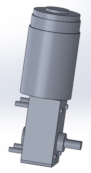
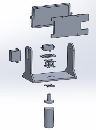
The above pictures are models of the base servo mechanism and the actual motors that are used. It was necessary to properly model these in solidworks in order to get a more accurate overall model of the pathfinder. The base servo mechanism mounts the servo that controls the pan motion of the smart phone holder. Adding the motors gives an accurate measurement of the width of the Pathfinder.
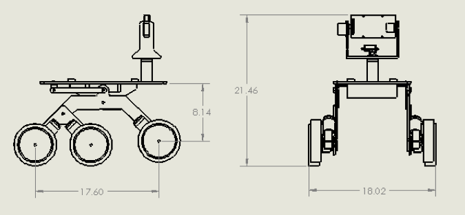

The above pictures show a 2-D drawing as well as a 3-D exploded view of the Pathfinder design. The overall dimensions of the design can be seen below.
Height: 21.6 inches
Width: 18.02 inches
Length: 23.60 inches
Floor to Top panel: 11.14 inches
The overall design can be broken into two basic sub-assemblies. These include the rocker bogie suspension system and the pan/tilt smart phone holder. Descriptions of these sub-assemblies can be seen in the next sections.
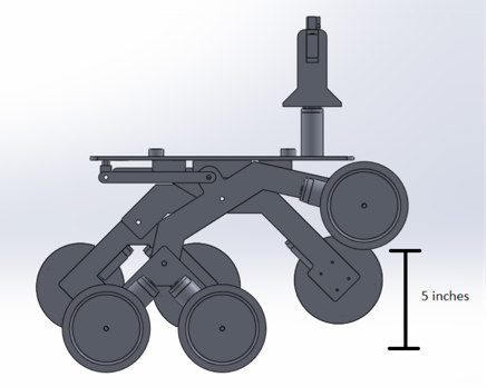
The rocker bogie suspension system that was utilized in our design is very similar to the one used on the Mars Spirit rover. This suspension system is good for uneven surfaces and requires no springs or dampening mechanisms. Each wheel can move up and down independent of one another. Another benefit of this suspension system is that the main body stays straight and upright while going up of down steep surfaces. This creates good weight distribution and helps prevent the Pathfinder from tipping over. The overall wheel clearance of the suspension system was designed to be 5 inches due to the fact that it will need to go upstairs that are about 5 inches tall. The diameter of the wheels is 6 inches, therefore the height of the Pathfinder from the ground to the bottom of the base platform is 11.14 inches.
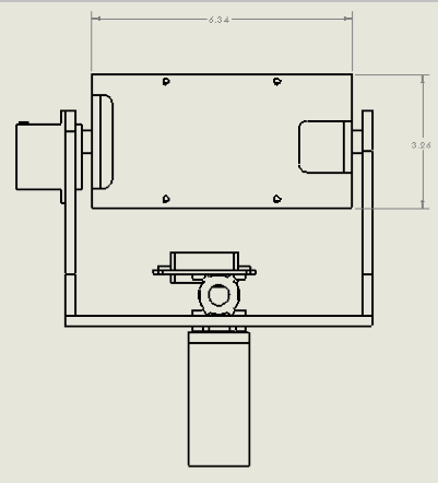
The pan/tilt smartphone holder is designed to hold a Samsung Galaxy S7 edge. The dimensions of the phone are 5.94 x 2.86 x 0.30 in. The holder case was designed to have the following dimensions: 6.34 x 3.26 x 0.7 in. The thickness of the case will be 0.2 inches which will allow for the phone to be fully covered. The front cover plate was designed to have cutouts in the appropriate locations. The cutouts can be seen in the picture above. These cutouts are for the camera and for the antennas in the phone. It is necessary that these do not get covered in order to obtain good signal strength. The pan/tilt servos will be able to move 180 degrees in both directions.
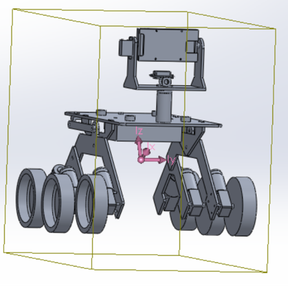
The goal of the design was to get the center of mass as low as possible. The picture above shows the center of mass in purple. The previous design had a center of mass the was above the main pivot point of the rocker bogie front arm. The design focused on lowering the center of mass below the pivot point. This was achieved by redesigning the top platform and lowing it an inch. Lowering it an inch meant that the clearance would also be 1 inch smaller which was a problem. This was solved by making the rocker bogie arms one inch longer. The electrical box and battery will also be mounted on the bottom too which helps make the center of mass lower.
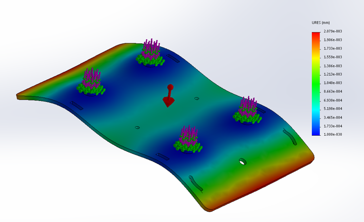
The top panel was analyzed to see how it would react to an outside force being applied to it. The top panel will carry the majority of the load which includes the Solar Panels, the Pan/Tilt Smartphone Holder, the Batteries and the Electronics. The above photo is an exaggerated simulation on how the panel may deform under certain stresses.

It will be necessary to properly interconnect the chassis to the solar panel assembly. The picture above shows the interconnection mounting points and the dimensions. 4 connection points will be used for optimal stability. These connection points will be raised pads with holes drilled through them. The solar panel assembly will then align with the holes and quick release pins win hold them in place. This will allow for quick removal of the panels.
By Jose Rodriguez (Electronics and Control)
Approved By Inna Echual (Project Manager)
Objective: Motors we need to select must be able to hold the panel at different angles with precision with maximum 12 volts and 2 amps to fulfill the sun tracking requirement. In order to do this, a minimum torque of 50 oz/in is required based on our calculations.
Stepper Motor:
Need to consider the positioning resolution because the number of steps per revolution range from 4 to 400.
Note: Resolution is expressed in degrees. Example- 1.8⁰ is 1.8360= 200 step/rev motor
Pros
Cons
DC Motor:
Pros
Cons
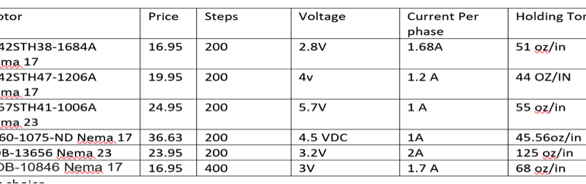
Based on the two key differences on these two motors, we concluded that we will need to use 2 stepper motors to control the sun tracking on the solar panels. Precision is needed and the stepper motor is the only motor that can be controlled to fulfill that precision requirement. In addition, a constant-holding torque is required to hold the panels and the stepper motors are able to provide this. Since the other panels do not require any precision or holding torque, DC motors are more acceptable to be used than stepper motors. The following table shown in Figure 1 will show the motors that I compared and based on my needs I picked one of the 6.
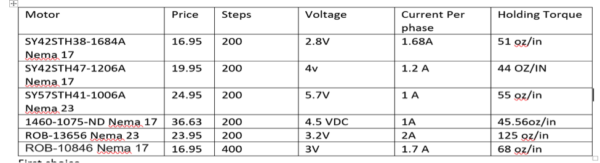
Figure 1: Stepper Motor Comparisons
Final Decision:
The final decision for making the sun tracking possible are the two stepper motors SY57STH41-1006A. They are my choice because it draws only 1 amp and has a holding torque of 55 oz/in, which is required to articulate the panels efficiently.
By Jose Alcantar, Electronics and Controls
A set of different types of sensors were considered for detecting no load conditions on the Pathfinder, these include:
Current Sensors: These type of sensors allow the user to monitor the current draw on each of the motors.
Flex Sensors: This type of sensor measures the deflection caused by bending of the sensor.
Pressure Sensor: This sensor typically measures the pressure of gases.
Micro switch: This type is a switch that is actuated by physical force
Each of these types of sensors presented both pros and cons when deciding on which to implement on the pathfinder. Starting with the flex sensor, the proposed idea was that as the pathfinder was traveling the suspension system would move and bend as the rover drove along. As soon as one of the wheels came off the ground, the flex sensor would detect this and shut off power to the motor. The biggest problem in implementing this idea is that the rocker bogie system does not bend while it is driving. This makes the sensor in the field unreliable.
The idea with the pressure sensor was that the pressure in the tires would be measured. This would be beneficial if the rover had air-filled tires, which would detect when the tires would come off the ground. With the new design of the rover, this would become an issue due to the use of foam-filled tires.
Similar with the flex sensor, the micro switch would detect any force on the sensor if the suspension lifted a tire off the ground. The problem with this is with the design of the rover, there would be no suitable areas to mount the sensor on the pathfinder.
The best option for the rover were the current sensors. Due to the current draw of each of the motors, a current sensor can be wired in series with the motor to measure the current. Of the different types of current sensors, two were selected as the best options. The two options were the use of a 0.51Ω current sensing resistor and the Adafruit INA219.
When considering the two options the main differentiator between the two was the cost. The Adafruit INA219 has a total cost of $9.95 and multiplying by six (one for each motor) the total comes out to about $60. The shunt resistor has a cost of about .56 cents each, the total coming out to being about $3.50. Another benefit of using the shunt resistor is the fact that the motor shield being used has a pin output specifically for the use of current sensing resistors. Ultimately, the shunt resistor appears to be the best option due to the cost, the easy implementation, and least use of pins.

By: Nick Lukin (Manufacturing and Design Engineer)
Two motor driver shields were taken into consideration for the Pathfinder Project, the Pololu VNH 5019 and the Adafruit V2.3. Each shield had its own pros and cons and there were a variety of factors that needed to be taken into consideration during the evaluation process. The figure below shows a comparison of both boards.

Table 1: Comparison of Polulu VNH 5019 and the Adafruit V2.3
Continuous and Peak current capabilities of each driver shield were evaluated in order to find out what each shield could handle. The motors that we chose to use are 12 volt DC worm gear motors. These motors have a no load current of 0.96 A, a full load current of 1.8 A, and a stall current of 4.8 A. The Pololu VNH 5019 can handle the loads of the motors while the Adafruit V2.3 cannot. The next factor considered was the number of pins used for communication between the Arduino Leonardo and each shield. The Pololu VNH 5019 requires a minimum of 6 pins to control 2 motors. In order to separately control each motor (6 motors) a total of 18 i/o pins would be needed and the Leonardo only has 20 i/o pins total. This creates an issue because pins will also be used to control servos and take in sensor inputs. The Adafruit V2.3 uses i2c for communication and therefore will only require two pins from the Leonardo (SCL and SDA). The next factor taken into consideration was the additional features that each board offered. The Pololu VNH 5019 has built in current sensors that could be used to meet the requirement of stopping each motor under no load conditions while the Adafruit V2.3 has built in servo control that could be used for the pan and tilt mobile phone holder. Each shield has its pros and cons but ultimately we chose to go with the Pololu VNH 5019 because it can handle the load of the DC motors that we plan to use. It is necessary for us to keep the motors that are presently on the Pathfinder because they can handle the heavy weight of the chassis and solar panels. In order to solve the pin issue associated with the Pololu VNH 5019 we plan to use a MCP23017 – i2c input/output port expander. This port expander will give us an additional 16 pins. Our design will use 3 Pololu VHH 5019 motor shields stacked on each other to drive 6 motors. We will also be able to utilize the built in current sensors in order to stop our motors under no load conditions.
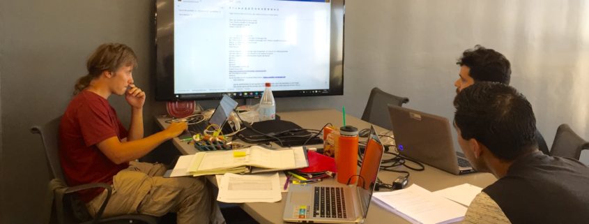
The team is using SVN -a Windows shell extension, to keep track and share all the designs, code, presentations and documentation of the project. Although the team is still getting familiar to the way the shell documents files, it seems to work fine. It has almost the same functionality as Google Drive or Dropbox with the only difference that SVN maintains the current and historical version of the files any of members “commit”.
Our Control and Electronics Engineer, Fabian Suske gave us a quick and easy workshop on how to get started. So, the following post is something he prepared to share with us and with the arxterra community.
By Fabian Suske.
Table of Contents
SVN is a revision based file sharing platform. Ideal for group projects. Every change will be saved and can be restored. So old versions can be restored if desired. SVN is especially helpful if more than one person is working on the same file or file group (e.g. Code).
SVN makes sure that no changes of one person are lost if a second one overrides the file because they worked on the same file at the same time. It also provides a merge tool for such a case.
In contrast to other file exchange platforms like Google Drive or OneDrive files are not automatically synced. The user has to actively sync the files (commit). This ensures that only working copies are stored on the platform.
SVN will be used to track the project process as well as a save file exchange platform. Especially in the manufacturing subsystem it will make cooperation easy.
A repository (server) is needed. A repository can be bought only or can be setup manually on a server. But the own server needs a static IP-Address and a DNS entry. Every revision is stored on the repository host. So large files or rapidly changing files (e.g. log files) are not designed to track with SVN.
To connect to the repository you need a client. I personally use TortoiseSVN.
You also need an account on the repository.
https://tortoisesvn.net/downloads.html
There are clients for MAC but I don´t know them
To interact with the repository you need to create a folder where ever you want your files to be. After you installed your client you should be able to right click on the folder you just created and select SVN Checkout

Then under URL enter the Repository URL:

You can then enter your User name and Password. Check “Save authentication”.
The program then downloads every file up to this point (revision).
Before you start working you need to make sure you have the newest version. To do so select SVN Update from the context menu

Save or copy a file in the SVN folder. If you’re done with your work (working pieces only) right click on the folder and press SVN Commit
Select all files that you’ve modified, created, deleted or added. If you just read something to don´t need to tick it.
Don’t forget to add a detailed description of what you’ve done! You don’t need to add details such as your name or the date. SVN will add such details on its own.
To commit it is important that you right click the folder icon. If you inside the folder you won’t see the context menu. Just go one folder up.

SVN sometimes has a problem when you just delete files with your windows command. To delete a file right click it and select tortoise SVN and then select delete

To make sure nobody overrides your stuff while you working on it you should lock it.
Select TortoiseSVN and then Get Lock

The lock will be released once you committed your work.
If you select Show log from the context menu a GUI will popup showing every step that has been committed.

Above you can see such a log. SVN provides you with revision number, the actions that happened (added/modifies/deleted), the person how changed it and the date.
It also provides a description message what has been done in this revision as well as a list of what action happed to every affected file.
We documented this workshop in Minutes 04
Sabina Subedi (Project Manager)
Adan Rodriguez (Mission, Systems & Test)
Jose Alcantar (Electronics & Controls)
Nick Lukin (Design & Manufacturing)
Table of Contents
By Sabina Subedi (Project Manager)
The WBS shows all the work that is to be completed by the Pathfinder – Chassis group. The WBS is arranged into three main sections or divisions – Mission Systems & Test, Electronics & Controls and Design & Manufacturing, where each section is a responsibility of the corresponding division member. The three sections are then divided into various groups, which include specific sets of tasks that are relevant to the group.

Figure 1: Work Breakdown Structure
By Sabina Subedi (Project Manager)
The top level schedule below was created using the generic schedule provided on the class website. This schedule consists of all tasks that are to be completed before the end of the semester, December 15th, 2016. The project milestones are broken down into four phases: Planning, Design, Assembly and Project Launch. The tasks within the different phases are then divided up by the divisions.
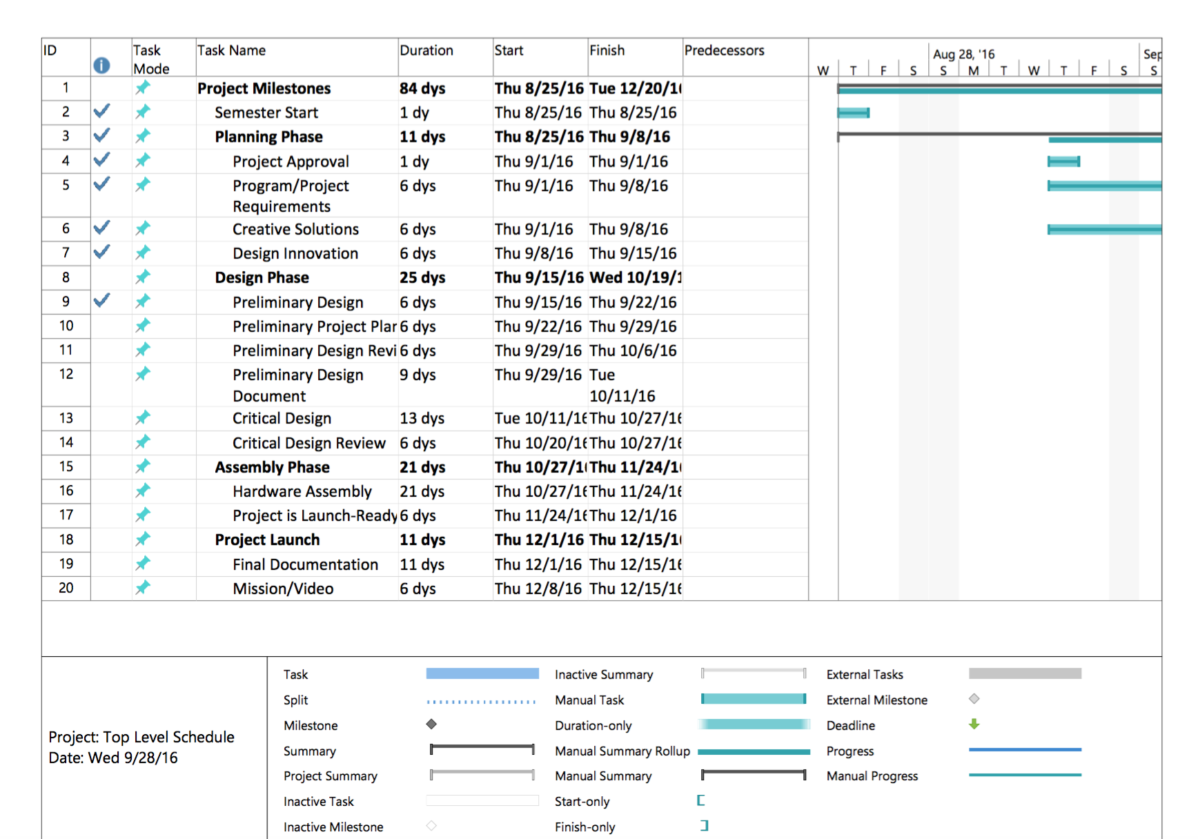
Figure 1: Top level schedule (Generic)
System/Subsystem level tasks
The generic top level schedule was then modified to include all system/Subsystem level tasks in accordance with the WBS above. All division members are assigned specific tasks that they are responsible for, per “Job Descriptions” document available on the class website. Main tasks then were broken down into sub-tasks, if applicable. All tasks include start and finish dates, as well as percent complete. Blue check mark denotes tasks that are 100% complete.
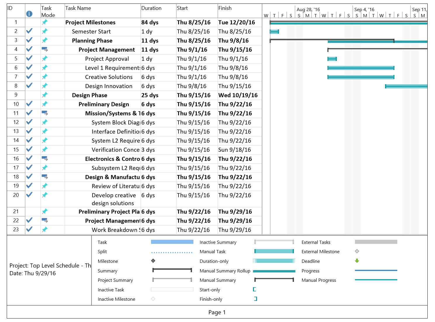
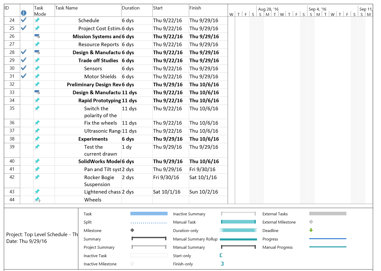
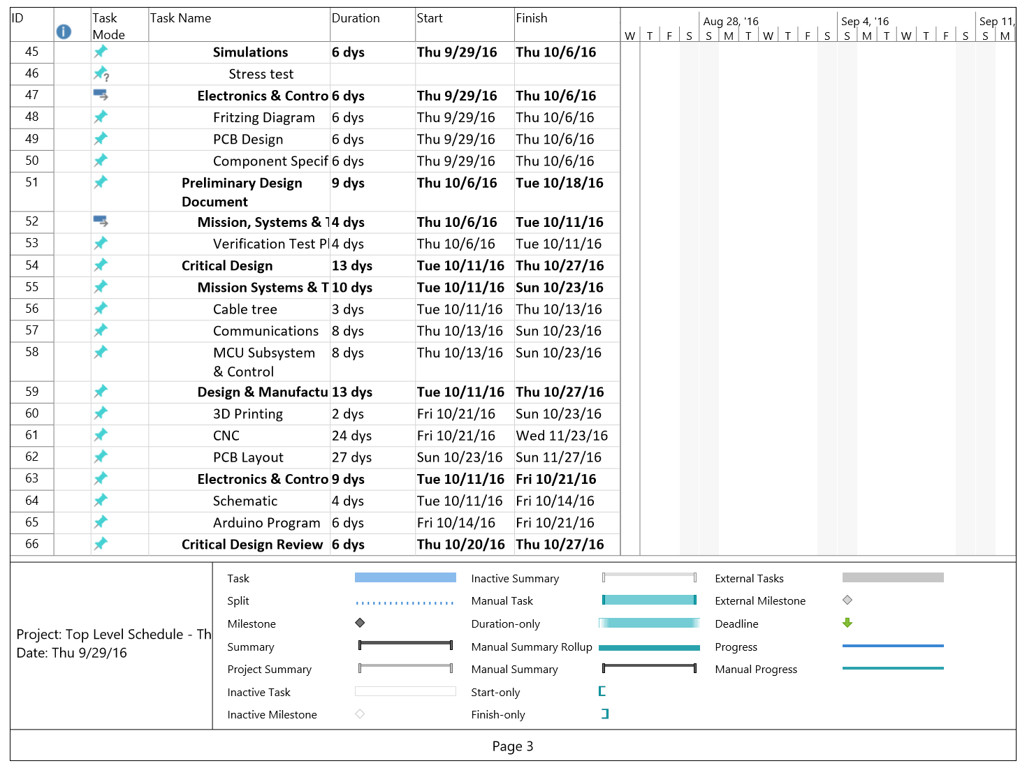

Figure 2: Schedule including System/Subsystem level tasks
The burn down chart below shows how many tasks are completed and how many are left. The project overview graph shows the percent completed as of today, September 29th 2016.
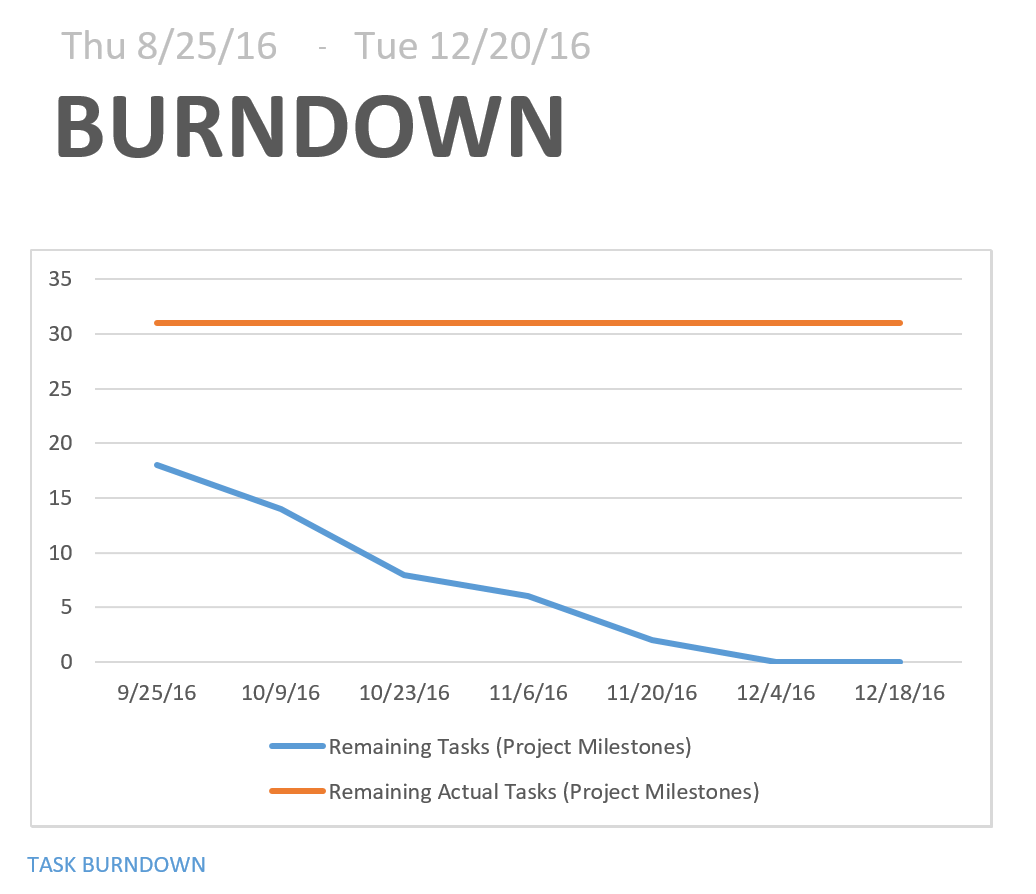
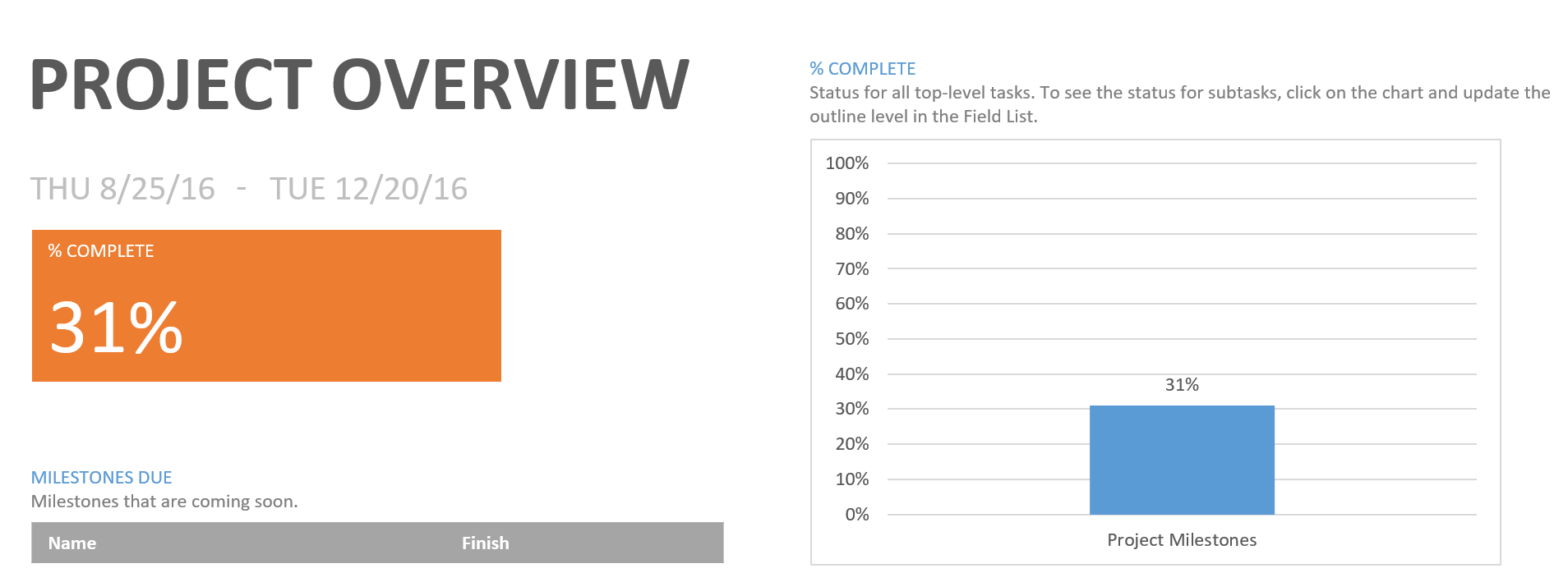
Figure 3: Task burndown chart along with project overview graph
By Adan Rodriguez (Mission Systems and Test Engineer)
This cost report is a rough estimate of the expected cost of each component on the Pathfinder. Our expected prices for each item excluded tax and shipping price. Tax and shipping prices were included in the Uncertainty category. Some of the items were marked at $0 for expected price because the item was either already on the Pathfinder from previous semester or the item was given to the team. Since there is no budget requirement, the Project Allocation was determined by adding up the expected price of each item and choosing an amount slightly higher than the total expected price.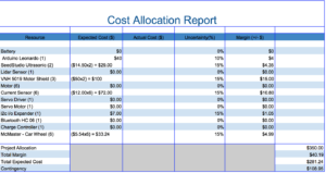
Figure 4: Cost Allocation Report
This power report displays the expected current drawn by each component that will be drawing power from the battery. The team had trouble identifying the current that would be drawn by the VNH 5019 motor shields. For now we have used rough estimate of the current drawn by the VNH 5019 motor shield by using the same current rating of the Arduino Leonardo. The battery being used on the Pathfinder has a power rating of 10,000 mAh. We considered the 4 hour duration of the mission in order to come up with the Project Allocation value. We simply divided the power rating of the battery by 4 in order to come up with a Project Allocation of 2,500 mAh.
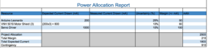
Figure 5: Power Allocation Report
This mass report is a rough estimate of the expected weight of each component on the Pathfinder. Some of the expected weight values are rough estimate because some of the item weight values were tough to find. Rough estimates were made relative to similar size of items. For example, the SeedStudio Ultrasonic sensors were estimated to weigh a fraction of the weight of the VNH 5019 motor shield because we had accurate weight values for the motor shields. The Mass Allocation Report will be updated once we actually weigh items with a scale. Since there is no weight requirement, the Project Allocation was determined by adding up the expect weight of each item and choosing an weight slightly higher than the total expected weight.

Figure 6: Mass Allocation Report
By Sabina Subedi (Project Manager)
The total expected cost is $281.24, based on the cost allocation provided above. The cost allocation report consists of rough approximations of the expected cost of each component. The components listed have not been purchased. Further trade-off studies are to be done before any purchases are made. Therefore, the total estimated cost is subject to change as the project progresses.
Preliminary Project Plan: http://web.csulb.edu/~hill/ee400d/Documentation%20Lecture%20Series/05%20Preliminary%20Project%20Plan.pdf
Generic Schedule: http://web.csulb.edu/~hill/ee400d/Lectures/Week%2005%20Project%20Plans%20and%20Reports/c_Generic%20Schedule.pdf
Job Descriptions:
http://web.csulb.edu/~hill/ee400d/Lectures/Week%2001%20Welcome/c_Job%20Descriptions.pdf
Resource Report: